
Related Manuals for CIS VCC-5CL5M


Summary of Contents for CIS VCC-5CL5M
- Page 1 VCC-5CL5M/R Rev.905-0073-00 Camera Link I/F 5M Pixels CMOS B/W and Color RAW Cameras VCC-5CL5M/R Product Specifications & Operational Manual CIS Corporation ©2016 CIS Corporation. All rights reserved.
-
Page 2: Table Of Contents
Flip Function ..........................22 11.11. Test Pattern Output Function ......................22 Factory Settings ............................22 Case for Indemnity (Limited Warranty) ......................23 CMOS Pixel Defect ............................ 23 Product Support ............................23 Ordering Information ..........................23 ©2016 CIS Corporation. All rights reserved. -
Page 3: Handling Precautions
Base Configuration Model 74.25MHz is up to 10m, although it depends on the specifications of the cable itself. 5 seconds shall be waited after power is turned ON to operate the camera properly. ©2016 CIS Corporation. All rights reserved. -
Page 4: Product Outline
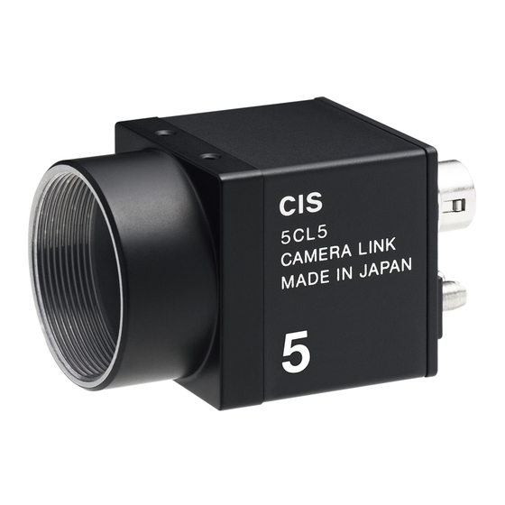
Product Outline VCC-5CL5M and VCC-5CL5R are Camera Link interfaced, and 5M resolution industrial camera modules. 5M pixels, 2/3 type CMOS sensor is utilized. Entire pixels (2248 x 2048) can be read out at 35fps (at 3 TAP output). 29mm cubic in size with 5M resolution, yet cost effective cameras. -
Page 5: Specifications
8/10/12bit (1 Tap,2 Tap), 8bit (3 Tap) Output data clock 74.25MHz (4) Cable length The maximum length: 10m (5) Sensitivity 400 lx 30fps (B/W: VCC-5CL5M) F5.6 200 lx 30fps (RAW: VCC-5CL5R) (6) Minimum illumination F1.4 0.1 lx 30fps (B/W: VCC-5CL5M) F1.4 1.0 lx 30fps (RAW: VCC-5CL5R) -
Page 6: Environmental Specifications
: 1 time / 6 sides (29) Operational Temperature/ Temperature: -5 ~ 45℃ environment Humidity Humidity: 20 ~ 60%RH with no condensation (30) Storage environment Temperature/ Temperature: -25 ~ 60℃ Humidity Humidity: 20 ~ 80%RH with no condensation ©2016 CIS Corporation. All rights reserved. -
Page 7: Part Names And Functions
2. Image sensor / Optical filter CMOS image sensor surface. A dummy glass is attached on the surface of the sensor (VCC-5CL5M). 3. Status LED Red LED lights when the camera is connected and power is turned ON. When camera internal setting is completed, Green LED lights (controllable) 4. - Page 8 CC4+, CC4- Not used 6. Product Name Plate When you need to contact CIS for the analysis or questions, please let us know of its model name and serial number on the product name plate. 7. Screw holes for camera installation Screw holes to attach the camera.
-
Page 9: Cmos Spectral Response
VCC-5CL5M/R Rev.905-0073-00 CMOS Spectral Response ※The lens characteristics and illuminant characteristics are excluded. 6.1. VCC-5CL5M (Mono) 6.2. VCC-5CL5R (Color) ©2016 CIS Corporation. All rights reserved. -
Page 10: Dimensions
VCC-5CL5M/R Rev.905-0073-00 Dimensions ©2016 CIS Corporation. All rights reserved. -
Page 11: Sensor Optical Axis Accuracy
VCC-5CL5M/R Rev.905-0073-00 Sensor Optical Axis Accuracy ©2016 CIS Corporation. All rights reserved. -
Page 12: Output Data Configuration
Output Data Array for Base Configuration X3_OUT3 P_C7 P_C6 P_B7 P_B6 P_A7 P_A6 X2_OUT2 DVAL FVAL LVAL P_C5 P_C4 P_C3 P_C2 X1_OUT1 P_C1 P_C0 P_B5 P_B4 P_B3 P_B2 P_B1 X0_OUT0 P_B0 P_A5 P_A4 P_A3 P_A2 P_A1 P_A0 CLK_OUT ©2016 CIS Corporation. All rights reserved. -
Page 13: Remote Communication Function
From the head of input character to the linefeed code CR (0x0d) or LF (0x0a) is analyzed as one command. ・ Please refer to the Section 11, Function Settings, for the details of address and data settings. ・ The sent command will be echoed back after it is received. ・ ©2016 CIS Corporation. All rights reserved. - Page 14 [Send] SU[sp]10[sp]30[¥r]or[¥n] [Returned Value] [¥r] [¥n] [Line feed] [Returned Value] >[sp] [Prompt + Space] 【Example of SAVE Command】 [Send] SAVE[¥r]or[¥n] [Returned Value] [¥r] [¥n] [Line feed] [Returned Value] >[sp] [Prompt +Space] [¥r]=CR(0x0D) [¥n]=LF(0x0A) [sp]=Space(0x20) ©2016 CIS Corporation. All rights reserved.
-
Page 15: Function Settings
ROI frame rate = ((Active Vline) + 32 = (V total lines)) x 1line: 13.4μs 2tap ROI frame rate = ((Active Vline) + 32 = (V total lines)) x 1line: 16.5μs 1tap ROI frame rate = ((Active Vline) + 32 =( V total lines)) x 1line: 33.0μs ©2016 CIS Corporation. All rights reserved. - Page 16 Formula for shutter time to read out at Trigger Shutter Mode All in common for 3tap, 2tap, and 1tap Preset Trigger Shutter time = (Setting Value) + 14μs Pulse Width Trigger Shutter time = (Trigger pulse width) + 14μs ©2016 CIS Corporation. All rights reserved.
-
Page 17: Shutter Time
1.60ms 1/3000s 322μs 1/2500s 394μs 1/1250s 773μs 1/6000s 161μs 1/5000s 196μs 1/2500s 377μs 1/12500s 81μs 1/10000s 96μs 1/5500s 179μs 1/25000s 41μs 1/20000s 47μs 1/12500s 80μs Manual Shutter as Continuous mode Address 24 setting value ©2016 CIS Corporation. All rights reserved. -
Page 18: Trigger Input / Een Output Settings
6pin Connector Trig + , Positive Edge 6pin Connector Trig + , Negative Edge 6pin Connector Trig - , Positive Edge 6pin Connector Trig - , Negative Edge EEN Output Positive logic (default) Negative logic ©2016 CIS Corporation. All rights reserved. -
Page 19: Black Level Control Values
Manual Gain Control Values Address Data Description 10bit x1: 0 (default) ~ x128: 420 (0 ~ 42dB ) 0.1dB step Noises on the images may be noticeable when gain is increased. Under x16 (24dB) is recommended. ©2016 CIS Corporation. All rights reserved. -
Page 20: White Balance Function
Adjustable color temperature range = 2700K ~ 10000K Example of manual color temperature settings (0,0) Color temperature MWB R/B gain R gain (%) B gain (%) 2800K 3200K 4000K 4500K 5500K Color Bayer Pattern 6500K 9000K ©2016 CIS Corporation. All rights reserved. -
Page 21: Roi Function (Region Of Interest)
0 Range: 0 ~ 2040 multiples of 4 12bit w: Column Width default: 2448 Range: 264 ~ 2448 multiples of 12 12bit h: Row Height default: 2048 Range: 8 ~ 2048 multiples of 4 ©2016 CIS Corporation. All rights reserved. -
Page 22: Sub-Sampling Function
This is the mode to increase its frame rate by reducing the pixel numbers to read out, reducing alternate pixels (reading intermittently) of both horizontal and vertical pixels. This mode cannot be used with ROI mode at the same time. When sub-sampling function is used, defective pixel correction cannot be applied. ©2016 CIS Corporation. All rights reserved. -
Page 23: Flip Function
HV cross line. Also, please note that HV cross line is adjusted its center position in conjunction with ROI function. 12. Factory Settings ©2016 CIS Corporation. All rights reserved. -
Page 24: Case For Indemnity (Limited Warranty)
CIS Corporation, at its option, repairs or replaces it at no charge to you. Products out of warranty period will be subject to charge. CIS repairs the products as long as it is repairable. CIS shall be exempted from taking responsibility and held harmless for damages or losses incurred by the following cases.
Need help?
Do you have a question about the VCC-5CL5M and is the answer not in the manual?
Questions and answers