
Related Manuals for CIS VCC-SXCL5M


Summary of Contents for CIS VCC-SXCL5M
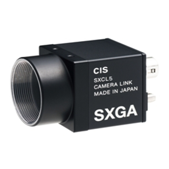
- Page 1 VCC-SXCL5M Rev.905-0156-04 Camera Link I/F CMOS MV Camera VCC-SXCL5M Product Specifications & Operational Manual CIS Corporation ©2018 CIS Corporation. All rights reserved.
-
Page 2: Table Of Contents
Remote Communication Function ........................26 Serial Communication ..........................26 Function Settings ............................ 28 5.2.1 The List of Preset Shutter ........................32 5.2.2 Calculating Exposure Time ........................34 5.2.3 Functions Unable to Set at the Same Time ................... 34 ©2018 CIS Corporation. All rights reserved. - Page 3 Camera Dimensions ..........................35 Optical Axis Accuracy ..........................36 Case for Indemnity (Limited Warranty) ........................ 37 Product Warranty ............................ 37 CMOS Pixel Defects ..........................37 Supplementary Note ............................37 Ordering Information ..........................37 Product Support ............................37 ©2018 CIS Corporation. All rights reserved.
-
Page 4: Handling Precautions
1.3 Disclaimers (Exception Clause) CIS shall be exempted from taking responsibility and held harmless for damages or losses incurred by the following cases. In case damages or losses are caused by earthquake, lightning strike, fire, flood, or other acts of God. -
Page 5: Precautions On Exporting
“Foreign Exchange Control Order”, and “Catch-All Controls”, and carefully research on your end customer and its applications to classify and determine if it is appropriate to export. ※ Refer to the METI web (Ministry of Economy, Trade and Industry) for the details. http://www.meti.go.jp/policy/anpo/englishpage.html ©2018 CIS Corporation. All rights reserved. -
Page 6: Product Outline
The purpose of this control software prepared is for users to check operation and evaluate our products. Please be noted that CIS does not customize the program nor provide source code. -
Page 7: Specifications
At 12bit output 264 ~ 1440 pixels (12pixels/step) Remote communication 115200/9600 baud selectable, data 8bit, Stop bit 1bit, No parity, XON/OFF invalid Power requirements 6 pins circular connector or PoCL (Auto selection) 6pin: 10.5~15V PoCL: 12V Power consumption 2.2W ©2018 CIS Corporation. All rights reserved. - Page 8 Storage Temperature -25 ~ +60°C Humidity 20 ~ 80%RH with no condensation [Note] The maximum of 5 seconds shall be waited until the camera operates normally after it is powered. ・ ©2018 CIS Corporation. All rights reserved.
-
Page 9: Camera Input And Output Signals Specifications
Power IN non-PoCL: Power Input (DC 12V typical) Not used EEN OUT Exposure Enable Output (Open Collector) Trigger IN- Trigger Input- (Isolated) Trigger IN+ Trigger Input+ (Isolated) HIROSE HR10-7R-6PA or equivalent GND (for Pin 1) ©2018 CIS Corporation. All rights reserved. -
Page 10: Camera Link Connector 12226-1100-00Pl (Sumitomo 3M)
CC3-, CC3+ Reserve Input differential pair for reception 12,25 CC4+, CC4- Reserve Input differential pair for reception 3.3.3 LED Indicator □ When the camera is connected and power is supplied, LED is lit up. ©2018 CIS Corporation. All rights reserved. -
Page 11: Cmos Spectral Response
VCC-SXCL5M Rev.905-0156-04 3.4 CMOS Spectral Response ※ The lens characteristics and illuminant characteristics are excluded. ©2018 CIS Corporation. All rights reserved. -
Page 12: Output Data Configuration
Output Data Array X3_OUT3 P_C7 P_C6 P_B7 P_B6 P_A7 P_A6 X2_OUT2 DVAL FVAL LVAL P_C5 P_C4 P_C3 P_C2 X1_OUT1 P_C1 P_C0 P_B5 P_B4 P_B3 P_B2 P_B1 X0_OUT0 P_B0 P_A5 P_A4 P_A3 P_A2 P_A1 P_A0 CLK_OUT ©2018 CIS Corporation. All rights reserved. -
Page 13: Video Output Format
□ 1Tap Base Configuration mode: At full frame scan output 1440pixel ・・・ □ 2Tap Base Configuration mode: At full frame scan output (factory setting) 1440pixel ・・・ □ 3Tap Base Configuration mode: At full frame scan output 1440pixel ・・・ ©2018 CIS Corporation. All rights reserved. -
Page 14: Timing Chart
Camera Link Port A 1435 1438 ・ ・ ・ ・ ・ ・ ・ ・ ・ ・ ・ ・ Camera Link Port B 1436 1439 ・ ・ ・ ・ ・ ・ ・ ・ ・ ・ ・ ・ Camera Link Port C 1437 1440 ・ ・ ・ ・ ・ ・ ・ ・ ・ ・ ・ ・ LVAL Out DVAL Out Effective Data : 480 CLK 4 CLK 1H = 484 CLK ©2018 CIS Corporation. All rights reserved. -
Page 15: Vertical Synchronous Timing
・ There is a readout period after exposure. Exposure time cannot be started for 12lines after FVAL is falled, so that frame rate becomes slower than the one for continuous shutter mode. ・ SP OUT (Exposure Out) + 14μs becomes the actual exposure time. ©2018 CIS Corporation. All rights reserved. -
Page 16: Camera Operational Specifications
Full frame 50 lines Continuous readout 50 lines Continuous readout Binning 50 lines Trigger Full frame 62 lines Trigger 58 lines Trigger Binning 60 lines [Note] ・ When changing mode settings, synchronization may be jumbled. ©2018 CIS Corporation. All rights reserved. -
Page 17: Roi (Region Of Interest) Mode
401). [Note] With CIS camera VCC-SXCL5M, horizontal effective pixel number can be set per multiple number of twelve. However, please be noted that there are some cases that effective pixel number is limited per eight pixels instead of multiple of twelve, depending on the Camera Link frame grabber board used. -
Page 18: Binning Mode
449.45 fps 257.88 fps [Note] ・ ROI mode cannot be set with binning mode at the same time. ・ Please turn OFF defective pixels correction. Binning mode is invalid when defective pixels correction is ON. ©2018 CIS Corporation. All rights reserved. -
Page 19: Gain Settings
※ x 10 equivalent values shall be set. Setting Examples In case of when setting +3.2dB with Manual gain. SU 100 15 SU 101 32 In case of when setting +10.5dB with Manual gain. SU 100 15 SU 101 105 ©2018 CIS Corporation. All rights reserved. -
Page 20: Settings Of Exposure Time
Full Size 1440×1080 720×540 1440×1080 ・Shutter value ・Shutter value ・Shutter value Preset 0 (1/95s) Exposure time clipped with 573 Preset 0 (1/95s) Exposure time 1080 lines lines. Readable with Address 114. Exposure time 1080 lines ©2018 CIS Corporation. All rights reserved. -
Page 21: Shutter Mode
Exposure time settings (Address 110 and ・ Address 111) are different for continuous reading out shutter mode, and for trigger shutter mode. Therefore, please confirm its exposure time setting as well when changing shutter mode (Address 51). ©2018 CIS Corporation. All rights reserved. -
Page 22: Fixed Trigger Shutter Mode
(Address 40), Camera operational mode (Address 41), Camera Link output clock (Address 49), Shutter mode (Address 51), Trigger polarity (Address 52), Trigger input selection (Address 53), Shutter (Address 110 and 111), and Flipping (Address 902 and 903), CIS recommends you to stop external trigger input once, before changing those. -
Page 23: Shading Correction
(Address 40), Camera operational mode (Address 41), Camera Link output clock (Address 49), Shutter mode (Address 51), Trigger polarity (Address 52), Trigger input selection (Address 53), Shutter (Address 110 and 111), and Flipping (Address 902 and 903). CIS recommends you to stop external trigger input once, before changing those. -
Page 24: Test Pattern Indication
ROI Area [Note] Shading correction data may not be proper when horizontal flip or vertical flip is performed. If you wish ・ to do shading correction after flipping, please execute shading detection (Address 907). ©2018 CIS Corporation. All rights reserved. -
Page 25: Defective Pixels Correction Function
For example, when X1, X2, X3, and X4 are already registered as defected pixels, X can be added to be registered but it cannot be corrected. [Note] Binning and Defective pixels correction cannot be used at the same time. ・ ©2018 CIS Corporation. All rights reserved. - Page 26 This is to delete all defective pixels data detected and registered by users, with Address 911. Please execute this when you wish to redo your detection and registration from the beginning, or when you wish to restore all the registration to the factory settings. SU 914 to execute. ©2018 CIS Corporation. All rights reserved.
- Page 27 Parameter 4: Indicates the number of the registered defective pixels per CH. (Data registered by users only.) Parameter 5: Error status of the registered data. Indicates if the data registered by users are appropriate. ©2018 CIS Corporation. All rights reserved.
-
Page 28: User Data Save / Readout Function
(Set a letter string in the double quotation). 4.11.2 Users Data Readout The set user data can be readout. 【Send】GU[sp]1000 【Returned Value】Setting Data[sp][¥r][¥n] 【Returned Value】>[sp] 4.12 Reset With CMOS sensor resetting, the image sensor is rebooted. ©2018 CIS Corporation. All rights reserved. -
Page 29: Remote Communication Function
The sent command is echoed back after it was received. ・ (4) Factory settings Input “INIT” to restore to the factory settings. (Data cannot be saved at this point). (5) Data save Input “SAVE” to save the camera settings. ©2018 CIS Corporation. All rights reserved. - Page 30 [Returned value] >[sp] [Prompt + Space] 【Example of SAVE Command】 [Send] SAVE[¥r]or[¥n] [Returned value] [¥r] [¥n] [Linefeed] [Returned value] >[sp] [Prompt + Space] ※SAVE Com m and is equivalent to SU 5. [¥r]=CR(0x0D) [¥n]=LF(0x0A) [sp]=Space(0x20) ©2018 CIS Corporation. All rights reserved.
-
Page 31: Function Settings
The sensitivity at 8bit output is four times better than the one at 10/12bit output. Section 8.1. Ordering Information. ※The initial value of serial baud rate can be selected per ordering. Please refer to the ©2018 CIS Corporation. All rights reserved. - Page 32 At pulse width trigger shutter mode, it is invalid. ※Shutter settings are independently different per shutter m odes. W hen changing shutter m ode (Address 51), please check exposure time settings (Address 110 and Address 111) as well. ©2018 CIS Corporation. All rights reserved.
- Page 33 Test pattern (Movie) 【Factory setting】 Horizontal flip Vertical flip 【Factory setting】 【Factory setting】 Shading correction Shading detection None Start calculating the shading correction table. 【WriteOnly】 Valid only when camera is in full frame scan operation. ©2018 CIS Corporation. All rights reserved.
- Page 34 The minimum of one letter and the maximum of thirty letters acquiring) can be set in the letter string. Save settings with SAVE command (SU 5). 【Factory setting = non letter string】 It shall not be restored by the INIT command (SU 0). ©2018 CIS Corporation. All rights reserved.
-
Page 35: The List Of Preset Shutter
※W hen the shutter tim e becom es bigger than its fram e rate with ROI and others, at continuous reading out shutter mode, it shall be clipped to the exposure time for that frame rate automatically. ©2018 CIS Corporation. All rights reserved. - Page 36 1/10000 1/10000 1/10000 Manual ※When the preset shutter time becomes bigger than its frame rate at continuous reading out shutter mode, it shall be clipped to the exposure time for that frame rate automatically. ©2018 CIS Corporation. All rights reserved.
-
Page 37: Calculating Exposure Time
Shading correction ○ ○ ○ Test pattern or ○ ○ ○ Cursor indication Defective pixels detection by users ○ × × Shading detection ○ × × Vertical flip / Horizontal flip ○ ○ ○ ©2018 CIS Corporation. All rights reserved. -
Page 38: Dimensions
VCC-SXCL5M Rev.905-0156-04 Dimensions 6.1 Camera Dimensions ©2018 CIS Corporation. All rights reserved. -
Page 39: Optical Axis Accuracy
VCC-SXCL5M Rev.905-0156-04 6.2 Optical Axis Accuracy ©2018 CIS Corporation. All rights reserved. -
Page 40: Case For Indemnity (Limited Warranty)
8.1 Ordering Information Baud rate is selectable for VCC-SXCL5M out of the two baud rates below. Please select and specify which baud rate you choose when ordering. (Please be noted that baud rate cannot be changed by user settings, but only by factory settings at its delivery.).
Need help?
Do you have a question about the VCC-SXCL5M and is the answer not in the manual?
Questions and answers