
Related Manuals for CIS VCC-SXCXP1SW


Summary of Contents for CIS VCC-SXCXP1SW
- Page 1 Rev.905-0230-01 CoaXPress I/F 1.3M SWIR Camera VCC-SXCXP1SW Product Specifications & Operational Manual CIS Corporation ©2022 CIS Corporation. All rights reserved.
-
Page 2: Table Of Contents
Fan Control / Temperature Control ....................20 4.24. Shading Correction ........................20 4.25. Noise Filter ..........................21 4.26. Defective Pixel Correction ......................21 4.27. Test Pattern Indication ........................24 4.28. Cursor Indication.......................... 24 4.29. LED Operational Mode ........................24 ©2022 CIS Corporation. All rights reserved. - Page 3 Case for Indemnity (Limited Warranty) ....................31 7.1. Product Warranty ......................... 31 7.2. CMOS Defective Pixels ........................31 7.3. Product Support ........................... 31 Appendix : Points to Note on Image Quality Characteristics ..............32 ©2022 CIS Corporation. All rights reserved.
-
Page 4: Precautions
□ The camera must not be used under conditions or environments other than those specified in this manual. □ Usage of VCC-SXCXP1SW for military related purposes is prohibited by List Controls for Export Trade Control Order. 1.3. Disclaimers (Exception Clause) CIS should not be liable for any damages or losses if;... -
Page 5: Product Outline
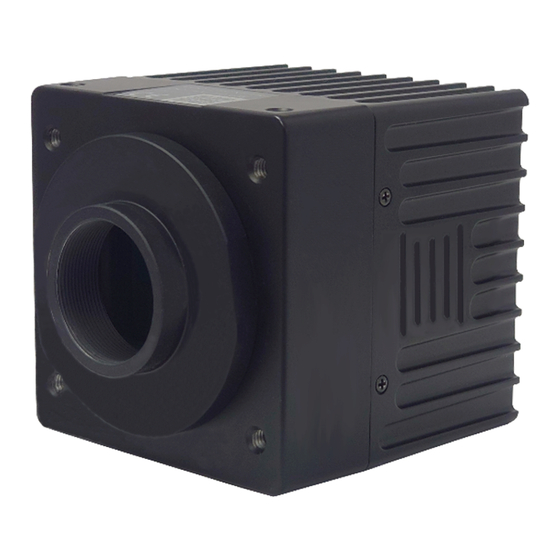
Rev.905-0230-01 Product Outline VCC-SXCXP1SW is a SWIR (Short Wave Infrared) camera with CoaXPress interface. Using 1.3M pixels resolution, 1/2” global shutter type SWIR sensor, this model is capable of inspecting invisible part of objects with detecting wavelength spectrum from 400nm to 1700nm. Must have function ready for FA applications, such as external trigger, ROI (vertical), gamma correction, shading correction, and defective pixel correction. -
Page 6: Specifications
Pulse width trigger shutter ・ Power requirements PoCXP: 18.5~26V Power consumption (Max) 3.6W [with free run] Mechanical Specifications Dimensions H: 65mm W: 65mm D: 65mm excluding projection. Weight Approx. 300g Lens mount C mount ©2021 CIS Corporation. All rights reserved. - Page 7 0℃ ~ +45°C Humidity 20 ~ 80%RH with no condensation. Recommended temperature 0℃ ~ +30°C Humidity 20 ~ 80%RH with no condensation. Storage temperature -25℃ ~ +60°C Humidity 20 ~ 80%RH with no condensation. ©2021 CIS Corporation. All rights reserved.
-
Page 8: Input And Output Specifications
3.2.2 12pins Circular Connector No.6, 7, 8, 9, and 10 pin: SIGNAL_OUT Circuit □ 5.0V CMOS logic level output Output voltage Low: 0.35Vdc (Max), High: 4.5Vdc (Min) +5.0V Camera internal circuit (CAMERA_INTERNAL) SIGNAL_OUT SN74LV1T32 (Equlvalent) ©2021 CIS Corporation. All rights reserved. -
Page 9: External Connector Pin Assignment
General output Line2 General output Line3 General output Line4 General output Line5 General output Line0 Trigger input Ground camera chassis ※NC=Non-Connection. Do not connect anything to the terminal. 3.3.2 75Ω BNC Connector BCJ-BPLHA (CANARE) ©2021 CIS Corporation. All rights reserved. -
Page 10: Led Indicator
※When Trigger Mode is off, LED blinks with 12.5Hz. When Trigger Mode is On, LED blinks with trigger cycle. (With high speed trigger, blinking may look like lighting.) 3.5. Spectral Response ※Excludes characteristics of lens and light source. ©2021 CIS Corporation. All rights reserved. -
Page 11: Camera Functions
UserSetLoad >Excute = Initialize(User setting) UserSet0 = User setting Save UserSetSave >Excute 4.3. Link Speed and Link Count Transfer Control ConnectionConfig CXP3_X1 CXP-3 : Link speed = 3.125Gbps, Link count = 1 (fixed) ・ ©2021 CIS Corporation. All rights reserved. -
Page 12: Pixel Format
※1 frame after switched full frame scan mode and partial scan mode, or changed partial settings becomes invalid. Especially with fixed trigger shutter mode and pulse width trigger shutter mode, input dummy trigger 8 times, and use 9 and later trigger signals as legitimate imaging signals. ©2021 CIS Corporation. All rights reserved. -
Page 13: Frame Rate
LVAL Out wait time wait time (Blank4H) is (Blank4H) is inserted inserted V Blanking Effective Line : 1032H Approx.33H Exposure Out Exposure Time Vertical sync. timing (with free run): TriggerMode = Off, TriggerSyncMode = LineSync ©2021 CIS Corporation. All rights reserved. -
Page 14: External Trigger Sync. Mode
Free run / FAST fixed / FAST pulse width trigger shutter Invalid overlapping operation. (Exposure while reading out images) ※Do not change SensorSyncMode while grabbing (acquiring) images. ※Change Sensor Sync Mode when there is no trigger input. ©2021 CIS Corporation. All rights reserved. -
Page 15: Trigger Sync. Mode And Delay Time To Start Exposure
Trigger sync. mode and delay time to start exposure CXP3_X1 Delay time to start exposure with H sync. trigger (LineSync) Approx. 1H ~ 2H Delay time to start exposure with CLK sync. trigger (ClockSync) Approx. 0.13µs ©2021 CIS Corporation. All rights reserved. -
Page 16: Restrictions On Timing For Trigger Pulse Input
If there is a trigger input with restricted timing as explained in the above, “IllegalTriggerFlag” becomes “1”. ・ Acquisition Control 0 or 1 IllegalTriggerFlag Device Control ErrorFlagReset (Execute) This is to reset IllegalTriggerFlag to “0”. ©2021 CIS Corporation. All rights reserved. -
Page 17: Fixed Trigger Shutter Mode H Sync. Trigger (Linesync)
Image Cxp Stream Idle Stream data Idle Stream data Idle Header Header LVAL Out FVAL Out Effective Line : 1032H Exposure Time Delay Trigger input ignore period TRIG IN Exposure Out Exposure time delay ©2021 CIS Corporation. All rights reserved. -
Page 18: Fast Fixed Trigger Shutter Mode Clk Sync. Trigger (Clocksync)
Image Image Cxp Stream Idle Stream data Idle Stream data Header Header LVAL Out FVAL Out Effective Line : 1032H Exposure Time Delay Trigger input ignore period TRIG IN Exposure Out Exposure time delay ©2021 CIS Corporation. All rights reserved. -
Page 19: Pulse Width Trigger Shutter Mode H Sync. Trigger (Linesync)
Stream data Idle Stream data Idle Header Header LVAL Out FVAL Out Effective Line : 1032H Exposure Time Delay① Exposure Time Delay② Trigger input ignore period TRIG IN ① ② Exposure Out Exposure time delay ©2021 CIS Corporation. All rights reserved. -
Page 20: Fast Pulse Width Trigger Shutter Mode Clk Sync. Trigger (Clocksync)
Stream data Idle Stream data Header Header LVAL Out FVAL Out Effective Line : 1032H Exposure Time Delay① Exposure Time Delay② Trigger input ignore period TRIG IN ① ② Exposure Out Exposure time delay ©2021 CIS Corporation. All rights reserved. -
Page 21: Exposure Time
Gain setting range is x1.00 to x128.0. User can set higher gain value more than x16.00. However, with high gain settings, noises will increase and image quality deteriorates. ※With 8-bit mode, camera internally adds x4.00 offset gain. Therefore, with more than x4.00 gain setting, deterioration of image quality is inevitable. ©2021 CIS Corporation. All rights reserved. -
Page 22: Gamma Correction
StandardMode ImageQualityMode LowNoiseMode □ Image Quality Mode StandardMode : Standard mode ・ LowNoiseMode : Valid only with Mono8. ・ With this mode, frame rate and sensitivity will deteriorate (equivalent to Mono10) but S/N improves. ©2021 CIS Corporation. All rights reserved. -
Page 23: Fan Control / Temperature Control
※When obtain correction data with trigger shutter mode, the data sometimes becomes unstable. In this case, change the trigger cycle in small measure and obtain correction data again. Before shading correction After shading correction ©2021 CIS Corporation. All rights reserved. -
Page 24: Noise Filter
Defective pixel correction function calculates value for X pixel referring to peripheral pixels (up and down, left and right). When all peripheral pixels, X1, X2, X3, and X4, as shown in the left, are already registered as defective pixels, user cannot correct X pixel. ©2021 CIS Corporation. All rights reserved. - Page 25 Normal operation (Number of defective pixels detected and registered by user) 0x000e0001(917505) Total number of defective pixel correction data exceeds the maximum number to register in one CH. 0x000e0002(917506) Total number of defective pixel correction data exceeds the maximum number to register. ©2021 CIS Corporation. All rights reserved.
- Page 26 : Defective type of the pixel designated with DefectPixelNumber out of the followings. White defects registered upon shipment from factory Black defects registered upon shipment from factory Defects registered by user Defects additionally registered by user 65535: Table without defects ©2021 CIS Corporation. All rights reserved.
-
Page 27: Test Pattern Indication
ErrorStatus Inactive ・ Active : Indication of communication status of CoaXPress ・ ErrorStatus : OFF with normal operation. Lights only with video transmission error or inappropriate trigger input. ・ Inactive : ALL LED OFF ©2021 CIS Corporation. All rights reserved. -
Page 28: Camera I/O
Section 4.32. External Lighting Control in this manual, and “VCC-SXCXP1SW Lighting Control Application Note” in a separate document. 4.31. User ID Save Set a letter string as DeviceUserID with up to 16 characters including terminal NUL letter (¥0). Set a letter string as DeviceUserString with up to 256 characters including terminal NUL letter (¥0). -
Page 29: External Lighting Control
Define emission pulse width and exposure time in advance. User can acquire images with emitting light in sequence per input triggers (or free run). For details, please refer to “VCC-SXCXP1SW Lighting Control Application Note” in a separate document. Digital IO Control... - Page 30 Line2 =Light3 LightWidth2 Line3 =Light2 LightWidth1 Line4 =Light1 LightWidth0 LightWidth0 Line5 =Light0 LightExposureDelay LightExposureDelay LightExposureDelay LightExposureDelay LightExposureDelay ExposureActive LightExposureTime0 LightExposureTime1 LightExposureTime2 LightExposureTime3 LightExposureTime4 FrameActive FramePeri od0 FramePeri od1 FramePeri od2 FramePeri od3 FramePeri od4 ©2021 CIS Corporation. All rights reserved.
-
Page 31: Factory Settings
Circular 12P setting (Fixed to Line0), LineSource FrameTrigger Line1~5 Off LightControlMode Emission trigger sequence is invalid DeviceUserID User set letter string (16 letters) DeviceUserString User set letter string (256 letters) ※PixelFormat and ImageQualityMode are not subject to UserSetLoad operation. ©2021 CIS Corporation. All rights reserved. -
Page 32: Dimensions
VCC-SXCXP1SW Rev.905-0230-01 Dimensions 6.1. Camera Dimensions 935-0176-00 (Unit: mm) ©2021 CIS Corporation. All rights reserved. -
Page 33: Optical Axis Accuracy
VCC-SXCXP1SW Rev.905-0230-01 6.2. Optical Axis Accuracy 937-0035-00 (Unit: mm) ©2021 CIS Corporation. All rights reserved. -
Page 34: Case For Indemnity (Limited Warranty)
If you use the product properly and discover a defect during the warranty period, and if that was caused by designing or manufacturing, CIS Corporation, at its option, repairs or replaces it at no charge to you. Products out of warranty period will be subject to charge. -
Page 35: Appendix : Points To Note On Image Quality Characteristics
Rev.905-0230-01 Appendix : Points to Note on Image Quality Characteristics Image sensor of VCC-SXCXP1SW contains InGaAs (Indium Gallium Arsenide) elements to acquire sensitivity in SWIR wavelength range. This makes image quality of VCC-SXCXP1SW significantly different from those with standard silicon CMOS image sensors.
Need help?
Do you have a question about the VCC-SXCXP1SW and is the answer not in the manual?
Questions and answers