
Related Manuals for CIS VCC-5CXP7M


Summary of Contents for CIS VCC-5CXP7M
- Page 1 Rev.905-0262-Z2 CoaXPress I/F 5M CMOS B/W Camera VCC-5CXP7M Product Specifications & Operational Manual CIS Corporation ©2022 CIS Corporation. All rights reserved.
-
Page 2: Table Of Contents
4.20. Sensor Black Level Adjustment......................24 4.21. Partial Scan (ROI) ........................25 4.22. 2x2 Binning Mode......................... 30 4.23. 1/2 Decimation Mode ........................31 4.24. Image Quality Selection Mode......................32 4.25. Shading Correction ........................32 ©2022 CIS Corporation. All rights reserved. - Page 3 6.1. Camera Dimensions ........................41 6.2. Optical Ax is Accuracy ........................42 Case for Indemnity (Limited Warranty)....................... 43 7.1. Product Warranty ......................... 43 7.2. CMOS Defective Pixels ........................43 7.3. Product Support ........................... 43 ©2022 CIS Corporation. All rights reserved.
-
Page 4: Handling Precautions
Unstable or improper power supply voltage may cause damages or malfunction of the camera. □ VCC-5CXP7M is a highly dense camera in a small foot print. CIS recommends you to install the camera on a metal plate to avoid heat. -
Page 5: Product Outline
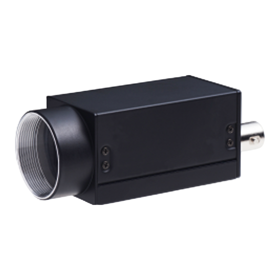
VCC-5CXP7M Rev.905-0262-Z2 Product Outline VCC-5CXP7M is a small B/W camera with CoaxPress interface. Using 1/1.8”, global shutter type 5M pixels CMOS image sensor, frame rate reaches 101fps with CXP6 8bit. Complies with CoaXPress Version 1.1.1 and transfers data up to 100m with CXP-3 and approx. 40m with CXP-6. -
Page 6: Specifications
PoCXP: 18.5 ~ 26V Power requirements Power consumption 3.3W typ. (CXP-3), 3.9W (CXP-6) [with free run] Mechanical Specifications Dimensions H: 29mm W: 29mm D: 55mm excluding projection. Weight Approx. 70g Lens mount C mount ©2022 CIS Corporation. All rights reserved. - Page 7 (100)G for ±X, ±Y, and ±Z 6 directions without packaging. Operational temperature 0 ~ +45°C Humidity: 20 ~ 80%RH with no condensation. Storage temperature -25 ~ +60°C Humidity: 20 ~ 80%RH with no condensation. ©2022 CIS Corporation. All rights reserved.
-
Page 8: Input And Output Specifications
□ Output voltage Low: 0.35Vdc (Max.), High: 4.5Vdc (Min.) □ This is to output a timing signal of the camera. Set a signal with Line Source of Digital IO Control. +5.0V (CAMERA_INTERNAL) SIGNAL_OUT SN74LV1T32DCKR (Equivalent) ©2022 CIS Corporation. All rights reserved. -
Page 9: External Connector Pin Assignment
Green Lighting Completion of connection between device and host. Green Fast Blinking [12.5Hz] Transmitting video data. Orange Slow Blinking [1Hz] Waiting for a trigger input. Red Fast Blinking [12.5Hz] System error / Trigger error ©2022 CIS Corporation. All rights reserved. -
Page 10: Spectral Response
VCC-5CXP7M Rev.905-0262-Z2 3.4. Spectral Response ※ Excludes characteristics of lens, IR cut filter, and light source. ©2022 CIS Corporation. All rights reserved. -
Page 11: Output Timing
1H / 8ch CXP-3 Mono8 154.5 171.5 4.391 Mono10 154.5 252.5 5.481 Mono12 154.5 334.5 6.586 CXP-6 Mono8 154.5 2.195 Mono10 154.5 48.5 2.734 Mono12 154.5 89.5 3.286 Sensor Operation CLK = 74.25MHz ©2022 CIS Corporation. All rights reserved. -
Page 12: Vertical Sync. Timing
Effective Line : 2064H SP Out (Exposure Out) Exposure Time ※Time for frame varies according to video output format. ※For data out delay, refer to Section 4.9 Delay Time to Read Out (Read Out Delay). ©2022 CIS Corporation. All rights reserved. - Page 13 1 Frame [ms] CXP-3 Mono8 1032 1248 5.479 Mono10 1032 1216 6.665 Mono12 1032 1200 7.903 CXP-6 Mono8 1032 1248 2.740 Mono10 1032 1216 3.325 Mono12 1032 1200 3.943 Sensor Operation CLK = 74.25MHz ©2022 CIS Corporation. All rights reserved.
-
Page 14: Camera Functions
If you wish to change those values, set values with each command. Default UserSetLoad >Excute = Initialize(Factory setting) UserSetSelector UserSetLoad >Excute = Initialize(User setting) UserSet0 = User setting Save UserSetSave >Excute ©2022 CIS Corporation. All rights reserved. -
Page 15: Link Speed And Link Count
With ROI, the origin coordinates (0, 0) of OffsetX/OffsetY appears on the display screen regardless ・ On/Off of flipping. The following illustration shows coordinates according to the setting order of ReverseX/ReverseY ・ and ROI. ©2022 CIS Corporation. All rights reserved. - Page 16 OffsetX = X0 ReverseY = False ReverseY = True OffsetY = Y0 ReverseX = False Width = W0 X1 = 2472 – W0 – X0 Height = H0 Y1 = 2064 – H0 – Y0 ©2022 CIS Corporation. All rights reserved.
-
Page 17: Internal Sync. Mode (Free Run Mode)
FVAL Out Cxp Stream Image Image Idle Stream data Idle Stream data Header Header LVAL Out V Blank Effective Line : 2064H Exposure Out Exposure Time Vertical Sync timing (with free run) Trigger Mode=Off, PixelFormat=Mono8 ©2022 CIS Corporation. All rights reserved. -
Page 18: External Trigger Sync. Mode
FAST fixed/FAST pulse width trigger shutter mode Disables overlap operation (disables exposure while reading out video) ※ Change TriggerSyncMode when there is no trigger input. ※ Set LineSync mode to change the mode to free run mode. ©2022 CIS Corporation. All rights reserved. - Page 19 ・LevelHigh(TriggerWidth) ・Line0 ・TriggerSoftware >Excute ・LevelLow(TriggerWidth) ・ AcquisitionFrameRate: This is to show frame rate for internal sync mode (free run mode). ※Even with external trigger mode, this function shows frame rate for internal sync mode. ©2022 CIS Corporation. All rights reserved.
-
Page 20: Trigger Sync Mode And Delay Time To Start Exposure
Delay time to read out with CLK Sync Trigger Mono8 127H (ClockSync) Mono10 103H (2x2 Binning Sum, 1/2 Decimation) Mono12 Delay time to read out with CLK Sync Trigger Mono8 (ClockSync) Mono10 (2x2 Binning Ave) Mono12 ©2022 CIS Corporation. All rights reserved. -
Page 21: Restrictions On Timing Of Trigger Pulse Input
If there is a trigger input with restricted timing explained in the above, “IllegalTriggerFlag” becomes “1”. ・ Acquisition Control IllegalTriggerFlag 0 or 1 Device Control ErrorFlagReset Execute This is to reset IllegalTriggerFlag to “0”. ・ ©2022 CIS Corporation. All rights reserved. -
Page 22: Fixed Trigger Shutter Mode (Linesync) H Sync Trigger
Image Cxp Stream Idle Stream data Idle Stream data Idle Header Header LVAL Out FVAL Out Effective Line : 2064H Exposure Time Delay Trigger input ignore period TRIG IN Exposure Out Exposure time delay ©2022 CIS Corporation. All rights reserved. -
Page 23: Fast Fixed Trigger Shutter Mode (Clocksync) Clk Sync Trigger
Image Image Cxp Stream Idle Stream data Idle Stream data Header Header LVAL Out FVAL Out Effective Line : 2064H Exposure Time Delay Trigger input ignore period TRIG IN Exposure Out Exposure time delay ©2022 CIS Corporation. All rights reserved. -
Page 24: Pulse Width Trigger Shutter Mode (Linesync) H Sync Trigger
Stream data Idle Stream data Idle Header Header LVAL Out FVAL Out Effective Line : 2064H Exposure Time Delay① Exposure Time Delay② Trigger input ignore period TRIG IN ① ② Exposure Out Exposure time delay ©2022 CIS Corporation. All rights reserved. -
Page 25: Fast Pulse Trigger Shutter Mode (Clk Sync) Clk Sync Trigger
Stream data Idle Stream data Header Header LVAL Out FVAL Out Effective Line : 2064H Exposure Time Delay① Exposure Time Delay② Trigger input ignore period TRIG IN ① ② Exposure Out Exposure time delay ©2022 CIS Corporation. All rights reserved. -
Page 26: Exposure Time
Setting unit: per 1μ s (approximate value) □ ※ Slight differences occur because 74.25MHz clock generates shutter value. Calculation Formula: Exposure Time = Setting Value + Delay Time – 0.1us □ (Refer to Chart 4.14.1 for Delay Time.) ©2022 CIS Corporation. All rights reserved. -
Page 27: Gain
Values are 12 bit converted. With 10bit, values become equivalent to ±16. ・ With 8bit, values become equivalent to ±4. With 10-bit images, set values with 4 times of signal level. With 8-bit images, set values with 16 times of ・ signal level. ©2022 CIS Corporation. All rights reserved. -
Page 28: Partial Scan (Roi)
OffsetY Height Region3 OffsetY Height Region4 OffsetY Height Region5 OffsetY Height Region6 OffsetY Height Region7 Chart 4.2.1. ROI with full frame setting OffsetX Width OffsetY Height Region0 Chart 4.2.2. ROI with 2x2 binning setting ©2022 CIS Corporation. All rights reserved. - Page 29 With full frame setting, Width and OffsetX should be as follows. ・ 640 ≦ OffsetX + Width ≦ 2472 ※ OffsetX of all effective regions must be the same. ※ Width of all effective regions must be the same. ©2022 CIS Corporation. All rights reserved.
- Page 30 ( Region2 OffsetY ) ④ Partial scan effective lines 2 ⑧ Region[n] Width Partial scan start ( Region[n] OffsetX ) Video Out FVAL LVAL FVAL ① ② ③ ④ LVAL ⑤ ⑥ ⑦ ⑧ ⑨ ⑩ ©2022 CIS Corporation. All rights reserved.
- Page 31 Partial scan start position ( Region0 OffsetY ) ③ Partial scan effective lines 0 Partial scan start ( Region0 OffsetX ) Video Out FVAL LVAL FVAL ① ② ③ LVAL ④ ⑤ ⑥ ⑦ ⑧ ⑨ ⑩ ©2022 CIS Corporation. All rights reserved.
- Page 32 □ 1 frame immediately after changing partial scan settings will become invalid frame. Especially with fixed trigger shutter mode and pulse width trigger shutter mode, input a dummy trigger once and use the second and after as regular video signals. ©2022 CIS Corporation. All rights reserved.
-
Page 33: 2X2 Binning Mode
Chart 4.22.1-Frame Rate with Binning mode [fps] BinningHorizontalMode PixelFormat CXP6_X1 CXP3_X1 Mono8 365.0 182.5 (1236x1032) Mono10 300.7 150.0 Mono12 253.5 126.5 Mono8 101.8 50.9 (1236x1032) Mono10 82.0 40.9 Mono12 68.7 34.3 ※Ave is the same as full frame scan setting. ©2022 CIS Corporation. All rights reserved. -
Page 34: 1/2 Decimation Mode
・ Only full frame (1 region, 2472x2064) enables 1/2 decimation mode. Chart 4.23.1 Frame rate with 1/2 decimation mode [fps] DecimationHorizontalMode PixelFormat CXP6_X1 CXP3_X1 Discard Mono8 365.0 182.5 (1236x1032) Mono10 300.7 150.0 Mono12 253.5 126.5 ©2022 CIS Corporation. All rights reserved. -
Page 35: Image Quality Selection Mode
・ Shading correction is disabled with multiple ROI (more than 2 effective regions). ・ With multiple ROI (more than 2 effective regions) after disabling 2x2 binning, shading correction automatically disabled as shown in the illustration below. ©2022 CIS Corporation. All rights reserved. -
Page 36: Impulsenoisefilter
・ With multiple ROI (more than 2 effective regions) after disabling 2x2 binning, ImpulseNoiseFilter automatically turns OFF as shown in the illustration below. Effective regions = 1 2x2 Binning Mode Disable Binning ImpulseNoiseFilter ImpulseNoiseFilter [On] [On] Effective regions ≧ 2 ImpulseNoiseFilter [Off] ©2022 CIS Corporation. All rights reserved. -
Page 37: Defective Pixel Correction
(Execute) 0~2471 DefectPixelAddOffsetY ・ 0~2063 DefectPixelAddOffsetX ・ DefectPixelDelete (Execute) ・ Updating defective pixel data with coordinates X and Y. □ This is to update defective pixel data by specifying coordinates to add or delete. ©2022 CIS Corporation. All rights reserved. - Page 38 CH. (64) 0x000e0002 (917506) Total number of defective pixel correction data exceeds the maximum number ©2022 CIS Corporation. All rights reserved. to register. (256 points) ※With some frame grabber board, error may be shown as decimal.
- Page 39 Function registers data up to that point, outputs error, and ends operation. (2) When there is no effective pixel around the pixel to add (on the left, right, top, and bottom), user can register but cannot correct that pixel. ©2022 CIS Corporation. All rights reserved.
- Page 40 This is to specify channel number of defective pixel correction. ・ DefectPixelChannelCount: Defective pixel count for the channel specified with ChannelNumber. ・ This is the sum total of defective pixel with factory count and user register count. ©2022 CIS Corporation. All rights reserved.
-
Page 41: Test Pattern Indication
□ This is to change operational mode of LED at the rear of camera. For information on lighting patterns, refer to Section 3.3.3. LED Indicator. DeviceControl Active DeviceIndicatorMode ErrorStatus Inactive ・ Active: Indication of communication status of CoaXPress. ・ ErrorStatus: OFF with normal operation. Lights only with system error. ・ Inactive: ALL LED OFF ©2022 CIS Corporation. All rights reserved. -
Page 42: Camera Timing Output
(Read Only) DeviceTemperatureSelector: This is to select the point of the device to measure temperature. ・ Fixed with sensor for VCC-5CXP7M. DeviceTemperature: This is to indicate temperature of the image sensor. ・ [Note] This is a reference temperature and not the actual temperature. -
Page 43: Factory Settings
Cursor color White/Black DeviceIndicatorMode Active LED indicator LineSource Circular connector 6P-3pin output DeviceUserID User set letter string (16 letters) DeviceUserString User set letter string (256 letters) ※ ConnectionConfig, PixelFormat, and ImageQualityMode are not subject to UserSetLoad. ©2022 CIS Corporation. All rights reserved. -
Page 44: Dimensions
VCC-5CXP7M Rev.905-0262-Z2 Dimensions 6.1. Camera Dimensions ©2022 CIS Corporation. All rights reserved. -
Page 45: Optical Axis Accuracy
VCC-5CXP7M Rev.905-0262-Z2 6.2. Optical Axis Accuracy ©2022 CIS Corporation. All rights reserved. -
Page 46: Case For Indemnity (Limited Warranty)
CIS applies defective pixel correction prior to shipment of the product. However, the number of defective pixels are subject to increase due primarily to the effect of cosmic rays. Due to this nature, CIS should not hold responsible for the natural increase of defective pixels.
Need help?
Do you have a question about the VCC-5CXP7M and is the answer not in the manual?
Questions and answers