
Related Manuals for CIS VCC-5CXP7R


Summary of Contents for CIS VCC-5CXP7R
- Page 1 Rev.905-0263-F1 CoaXPress I/F 5M CMOS Color (RAW) Camera VCC-5CXP7R Product Specifications & Operational Manual (Preliminary) CIS Corporation ©2023 CIS Corporation. All rights reserved.
-
Page 2: Table Of Contents
4.20. Sensor Black Level Adjustment......................23 4.21. Partial Scan (ROI) ........................23 4.22. White Balance ..........................26 4.23. Image Quality Selection Mode......................27 4.24. Shading Correction ........................27 4.25. Impulse Noise Filter ........................28 ©2023 CIS Corporation. All rights reserved. - Page 3 6.1. Camera Dimensions ........................35 6.2. Optical Ax is Accuracy ........................36 Case for Indemnity (Limited Warranty)....................... 37 7.1. Product Warranty ......................... 37 7.2. CMOS Defective Pixels ........................37 7.3. Product Support ........................... 37 ©2023 CIS Corporation. All rights reserved.
-
Page 4: Handling Precautions
Unstable or improper power supply voltage may cause damages or malfunction of the camera. □ VCC-5CXP7R is a highly dense camera in a small foot print. CIS recommends you to install the camera on a metal plate to avoid heat. -
Page 5: Product Outline
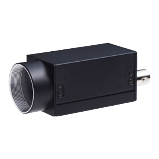
VCC-5CXP7R Rev.905-0263-F1 Product Outline VCC-5CXP7R is a small color (RAW) camera with CoaxPress interface. Using 1/1.8”, global shutter type 5M pixels CMOS image sensor, frame rate reaches 101fps with CXP6 8bit. Complies with CoaXPress Version 1.1.1 and transfers data up to 100m with CXP-3 and approx. 40m with CXP-6. -
Page 6: Specifications
PoCXP: 18.5 ~ 26V Power requirements Power consumption 3.3W typ. (CXP-3), 3.9W (CXP-6) [with free run] Mechanical Specifications Dimensions H: 29mm W: 29mm D: 55mm excluding projection. Weight Approx. 70g Lens mount C mount ©2023 CIS Corporation. All rights reserved. - Page 7 (100)G for ±X, ±Y, and ±Z 6 directions without packaging. Operational temperature 0 ~ +45°C Humidity: 20 ~ 80%RH with no condensation. Storage temperature -25 ~ +60°C Humidity: 20 ~ 80%RH with no condensation. ©2023 CIS Corporation. All rights reserved.
-
Page 8: Input And Output Specifications
□ Output voltage Low: 0.35Vdc (Max.), High: 4.5Vdc (Min.) □ This is to output a timing signal of the camera. Set a signal with Line Source of Digital IO Control. +5.0V (CAMERA_INTERNAL) SIGNAL_OUT SN74LV1T32DCKR (Equivalent) ©2023 CIS Corporation. All rights reserved. -
Page 9: External Connector Pin Assignment
Green Lighting Completion of connection between device and host. Green Fast Blinking [12.5Hz] Transmitting video data. Orange Slow Blinking [1Hz] Waiting for a trigger input. Red Fast Blinking [12.5Hz] System error / Trigger error ©2023 CIS Corporation. All rights reserved. -
Page 10: Spectral Response
VCC-5CXP7R Rev.905-0263-F1 3.4. Spectral Response ※ Excludes characteristics of lens, IR cut filter, and light source. ©2023 CIS Corporation. All rights reserved. -
Page 11: Output Timing
1H / 8ch for 1H / 8ch [us] CXP-3 BayerRG/GR/GB/BG 8 8.781 BayerRG/GR/GB/BG 10 10.976 BayerRG/GR/GB/BG 12 13.172 CXP-6 BayerRG/GR/GB/BG 8 4.391 BayerRG/GR/GB/BG 10 5.481 BayerRG/GR/GB/BG 12 6.586 Sensor Operation CLK = 74.25MHz ©2023 CIS Corporation. All rights reserved. -
Page 12: Vertical Sync. Timing
2064 2236 19.635 BayerRG/GR/GB/BG 10 2064 2224 24.412 BayerRG/GR/GB/BG 12 2064 2208 29.083 CXP-6 BayerRG/GR/GB/BG 8 2064 2236 9.817 BayerRG/GR/GB/BG 10 2064 2224 12.191 BayerRG/GR/GB/BG 12 2064 2208 14.542 Sensor Operation CLK = 74.25MHz ©2023 CIS Corporation. All rights reserved. -
Page 13: Camera Functions
UserSetLoad so that camera keeps values in operation. If you wish to change those values, set values with each command. Default UserSetLoad >Excute = Initialize(Factory setting) UserSetSelector UserSetLoad >Excute = Initialize(User setting) UserSet0 = User setting Save UserSetSave >Excute ©2023 CIS Corporation. All rights reserved. -
Page 14: Link Speed And Link Count
Bayer 10 bit (ReverseX= On, ReverseY= On) BayerBG12: Bayer 12 bit (ReverseX= On, ReverseY= On) R G Bayer Pattern of VCC-5CXP7R is ”RGGB” as shown in the picture left. Refer to section 4.5 Flip. When image is flipped in X and Y direction, G B... -
Page 15: Flip
OffsetX = X0 ReverseY = False ReverseY = True OffsetY = Y0 ReverseX = False Width = W0 X1 = 2472 – W0 – X0 Height = H0 Y1 = 2064 – H0 – Y0 ©2023 CIS Corporation. All rights reserved. -
Page 16: Internal Sync. Mode (Free Run Mode)
Cxp Stream Image Image Idle Stream data Idle Stream data Header Header LVAL Out V Blank Effective Line : 2064H Exposure Out Exposure Time Vertical Sync timing (with free run) Trigger Mode=Off, PixelFormat= BayerRG/GR/GB/BG8 ©2023 CIS Corporation. All rights reserved. -
Page 17: External Trigger Sync. Mode
FAST fixed/FAST pulse width trigger shutter mode Disables overlap operation (disables exposure while reading out video) ※ Change TriggerSyncMode when there is no trigger input. ※ Set LineSync mode to change the mode to free run mode. ©2023 CIS Corporation. All rights reserved. - Page 18 ・LevelHigh(TriggerWidth) ・Line0 ・TriggerSoftware >Excute ・LevelLow(TriggerWidth) ・ AcquisitionFrameRate: This is to show frame rate for internal sync mode (free run mode). ※Even with external trigger mode, this function shows frame rate for internal sync mode. ©2023 CIS Corporation. All rights reserved.
-
Page 19: Trigger Sync Mode And Delay Time To Start Exposure
Delay time to read out with H Sync Trigger (LineSync) BayerRG/GR/GB/BG 8 (Full frame) BayerRG/GR/GB/BG 10 BayerRG/GR/GB/BG 12 Delay time to read out with CLK Sync Trigger (ClockSync) BayerRG/GR/GB/BG 8 (Full frame) BayerRG/GR/GB/BG 10 BayerRG/GR/GB/BG 12 ©2023 CIS Corporation. All rights reserved. -
Page 20: Restrictions On Timing Of Trigger Pulse Input
Input more than 1H width pulse with trigger signals. Please refer to chart below for Time for 1H. □ Full frame / ROI: Chart 3.5.1.1 ・ Exposure output means exposure period. □ Exposure Out actual exposure period ©2023 CIS Corporation. All rights reserved. -
Page 21: Fast Fixed Trigger Shutter Mode (Clocksync) Clk Sync Trigger
Delay time from detecting the trigger edge in the camera to start exposure (Exposure Time Delay) is □ approx. 0.1µs. Input more than 1µs width pulse with trigger signals. □ Exposure output means exposure period. □ Exposure Out actual exposure period Accepts no trigger input while outputting video images. □ ©2023 CIS Corporation. All rights reserved. -
Page 22: Pulse Width Trigger Shutter Mode (Linesync) H Sync Trigger
Exposure Out actual exposure period Camera ignores trigger inputs during exposure period (Exposure Time). Input more than 1 frame cycle with □ trigger signals. ©2023 CIS Corporation. All rights reserved. -
Page 23: Fast Pulse Trigger Shutter Mode (Clk Sync) Clk Sync Trigger
Pulse width is 1µs (minimum) ~ approx. 2 frames. Functionally, there is no upper limitation but noises such as dark noise and shading noise may become noticeable with long timer exposure. Exposure output means exposure period. □ Exposure Out actual exposure period ©2023 CIS Corporation. All rights reserved. -
Page 24: Exposuretime
・ With internal sync mode, set a smaller value than ExposureTimeMax. ・ With H sync trigger mode (LineSync), effective line count (including with Partial setting) clips Exposure Time. ・ With CLK sync trigger mode (ClockSync), you can set Exposure Time from 91us to 200ms. ©2023 CIS Corporation. All rights reserved. -
Page 25: Calculation Formula For Manual Shutter With H Sync Mode
(approx. 20ms: refer to Command ACK as a rough guide). If user changes gamma coefficient while waiting for a trigger input, camera outputs images with updated gamma table with a trigger after completion of rewriting gamma table. ©2023 CIS Corporation. All rights reserved. -
Page 26: Sensor Black Level Adjustment
640~2472 (Multiple of 8) Width 8~2064 (Multiple of 8) Height 0~1832 (Multiple of 8) OffsetX 0~2056 (Multiple of 8) OffsetY [1]: When number of effective region is 1, user can set multiple of 4. ©2023 CIS Corporation. All rights reserved. - Page 27 ※ OffsetX of all effective regions must be the same. ※ Width of all effective regions must be the same. With shading correction ON, effective region must be 1. ・ With impulse noise filter ON, effective region must be 1. ・ ©2023 CIS Corporation. All rights reserved.
- Page 28 ⑨ : Entire effective pixels for 1 line (before ROI) ⑩ : Entire pixels for 1 line To set several partial scan areas, make sure to set start positions and effective lines not to overlap with other areas. ©2023 CIS Corporation. All rights reserved.
-
Page 29: White Balance
When BlanaceRatioSelector = Red/Blue, white balance will be invalid if user sets 1.0 for both BalanceRatioRed and BalanceRatioBlue. [Note] Please adjust white balance gain while camera is in operation. (White balance adjustment become ・ invalid when camera is not outputting video). ©2023 CIS Corporation. All rights reserved. -
Page 30: Image Quality Selection Mode
・ Execute UserSetSave to save correction data of Table1~Table 3 to non-volatile memory at the same time. ・ Correction data is not subject to Default of UserSetLoad. ・ Make sure to turn ON ShadingCorrectionDataSelector. ©2023 CIS Corporation. All rights reserved. -
Page 31: Impulse Noise Filter
This is not subject to UserSetDefault. User can register up to 256 points. (Note: Up to 64 points per CH.) □ [CH (Channel)] Camera performs image processing with 4 CH interleave. (0,0) (1,0) (2,0) (3,0) (0,1) (1,1) (2,1) (3,1) ©2023 CIS Corporation. All rights reserved. - Page 32 8 bit images, specify a value of 16 times of signal level as a threshold value. ・ DefectDetection: This is to detect defective pixels. Function automatically registers pixels that exceed the level specified with DefectDetectionThresholdValue. ©2023 CIS Corporation. All rights reserved.
- Page 33 ・ When DefectDetectionStatus becomes error (0x000e0001 and 0x000e0002), re-acquire defect pixels correction data as follows. (1) Select DefectCorrectMode = Reacquire, change threshold value, and execute DefectDetection. (2) Execute DefectPixelDefault to delete user-defect pixel correction data, change threshold value, and execute DefectDetection. ©2023 CIS Corporation. All rights reserved.
- Page 34 This is to specify channel number of defective pixel correction. ・ DefectPixelChannelCount: Defective pixel count for the channel specified with ChannelNumber. ・ This is the sum total of defective pixel with factory count and user register count. ©2023 CIS Corporation. All rights reserved.
-
Page 35: Test Pattern Indication
□ This is to change operational mode of LED at the rear of camera. For information on lighting patterns, refer to Section 3.3.3. LED Indicator. DeviceControl Active DeviceIndicatorMode ErrorStatus Inactive ・ Active: Indication of communication status of CoaXPress. ・ ErrorStatus: OFF with normal operation. Lights only with system error. ・ Inactive: ALL LED OFF ©2023 CIS Corporation. All rights reserved. -
Page 36: Camera Timing Output
(Read Only) DeviceTemperatureSelector: This is to select the point of the device to measure temperature. ・ Fixed with sensor (Sensor temperature) for VCC-5CXP7R. DeviceTemperature: This is to indicate temperature of the image sensor. ・ [Note] This is a reference temperature and not the actual temperature. -
Page 37: Factory Settings
Cursor color White/Black DeviceIndicatorMode Active LED indicator LineSource Circular connector 6P-3pin output DeviceUserID User set letter string (16 letters) DeviceUserString User set letter string (256 letters) ※ ConnectionConfig, PixelFormat, and ImageQualityMode are not subject to UserSetLoad. ©2023 CIS Corporation. All rights reserved. -
Page 38: Dimensions
VCC-5CXP7R Rev.905-0263-F1 Dimensions 6.1. Camera Dimensions ©2023 CIS Corporation. All rights reserved. -
Page 39: Optical Axis Accuracy
VCC-5CXP7R Rev.905-0263-F1 6.2. Optical Axis Accuracy ©2023 CIS Corporation. All rights reserved. -
Page 40: Case For Indemnity (Limited Warranty)
CIS applies defective pixel correction prior to shipment of the product. However, the number of defective pixels are subject to increase due primarily to the effect of cosmic rays. Due to this nature, CIS should not hold responsible for the natural increase of defective pixels.
Need help?
Do you have a question about the VCC-5CXP7R and is the answer not in the manual?
Questions and answers