
Related Manuals for CIS VCC-5CXP4M


Summary of Contents for CIS VCC-5CXP4M
- Page 1 Rev. 905-0255-Z3 CoaXPress I/F 5M pixels CMOS (B/W) Camera VCC-5CXP4M Product Specifications & Operational Manual (P relim inary) CIS Corporation ©2021 CIS Corporation. All rights reserved.
-
Page 2: Table Of Contents
Camera Timing I/O ........................25 4.16 User ID ............................25 4.17 Temperature Indication ......................... 25 4.18 Connection Reset ......................... 26 4.19 Gamma Correction........................26 4.20 Image Quality Selection Mode......................26 Factory Settings ............................ 27 ©2021 CIS Corporation. All rights reserved. - Page 3 VCC-5CXP4M Rev.905-0255-Z3 Dimensions ............................28 Camera Dimensions ........................28 Optical Ax is Accuracy ........................29 Case for Indemnity (Limited Warranty)....................... 30 Product Warranty ......................... 30 CMOS Defective Pixels ........................30 Product Support ........................... 30 ©2021 CIS Corporation. All rights reserved.
-
Page 4: Handling Precautions
□ The camera must not be used under conditions or environments other than those specified in this manual. 1.3 Disclaimers (Exception Clause) CIS should not be liable for any damages or losses if; damages or losses are caused by earthquake, lightning strike, fire, flood, or other acts of God. -
Page 5: Product Outline
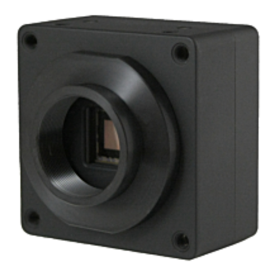
Rev.905-0255-Z3 Product Outline VCC-5CXP4M is B/W camera with CoaXPress interface. Using 2/3”, global shutter type 5.01M pixels CMOS image sensor. Complies with CoaXPress Version 1.1.1. Must have function ready for Machine Vision applications such as trigger shutter, ROI, Gain, black level adjustment, defective pixel correction, and PoCXP. Suitable for various FA/Machine vision applications. -
Page 6: Specifications
(The cable length of circular connector power supply cable must be less than 10m.) Power consumption (Max) 4.6W (CXP-6 2lane) [with free run] Mechanical Specifications Dimensions H:55mm W:55mm D:30mm excluding projection. Weight Approx. 140g Lens mount C mount ©2021 CIS Corporation. All rights reserved. -
Page 7: Input And Output Specifications
□ 5.0V CMOS logic level output □ Output voltage Low: 0.55Vdc (Max.), High: 3.8Vdc (Min.) □ This is to output timing signals generated in the camera. Set the signal to output with LineSource of DigitalIOControl. ©2021 CIS Corporation. All rights reserved. -
Page 8: External Connector Pin Assignment
※When supply power from 6pins circular connector, stop supplying power from CoaXPress cable to avoid malfunction of the camera. 3.3.2 75Ω BNC Connector CoaXPress video output signals □ CXP 1 is for PoCXP. □ CXP 2 CXP 1 (For PoCXP) ©2021 CIS Corporation. All rights reserved. -
Page 9: Led Indicator
※When there are no cable connections for the number of links designated with ConnectionConfig, LED will be Green/Orange fast blinking [12.5Hz] 3.4 Spectral Response ※ Excludes characteristics of lens, optical glass, and light source. ©2021 CIS Corporation. All rights reserved. -
Page 10: Frame Rate
※Please refer to Section 3.5.1. Frame rate of Internal Trigger Sync. Mode for the time for 1 line. ※Please refer to Section 4.6.2. External Trigger Sync Mode for the details on external sync .mode. ©2021 CIS Corporation. All rights reserved. -
Page 11: Camera Functions
Please refer to the table below for the combination for save settings and execute calling. UserSetSelector UserSetLoad/Save Status Default UserSetLoad Call factory settings. UserSetSave - (Not subject to execute.) UserSet0 UserSetLoad Call user settings. UserSetSave Save user settings. ©2021 CIS Corporation. All rights reserved. -
Page 12: Link Speed And Link Count
※ When executing Flip operation with ROI at the same time, the origin coordinate (0) will be on the display ing screen regardless of True/False of flip setting. The coordinates associated with the setting order of ReverseY and ROI are shown in the next page. ©2021 CIS Corporation. All rights reserved. -
Page 13: Trigger Mode
TriggerSelector : Trigger selector (Link with TriggerMode) AcquisitionStart : Operates with internal sync. mode (Free run mode) (TriggerMode = Off) FrameStart : Operates with external trigger mode (TriggerMode = On) ※Do not change TriggerSelector while grabbing (acquiring image). ©2021 CIS Corporation. All rights reserved. -
Page 14: Internal Sync. Mode (Free Run Mode)
□ User can select detailed function with following commands. (Make sure to stop inputting triggers while selecting function.) Acquisition Control LineSync TriggerSyncMode ClockSync LinkTrigger0 TriggerSource Line0 Software TriggerSoftware (Execute) RisingEdge FallingEdge TriggerActivation LevelHigh LevelLow ©2021 CIS Corporation. All rights reserved. -
Page 15: Fixed Trigger Shutter Mode + H Sync Trigger (Linesync)
□ There is a restriction for trigger input. Please refer to Section 4.6.7. Restrictions on Trigger Pulse Input Timing. □ The following shows the timing chart and the timing parameter with internal sync. mode + H sync trigger (LineSync) ©2021 CIS Corporation. All rights reserved. -
Page 16: Fixed Trigger Shutter Mode + Clk Sync. Trigger (Clocksync)
□ There is a restriction for trigger input. Please refer to Section 4.6.7. Restrictions on Trigger Pulse Input Timing. □ The following shows the timing chart and the timing parameter with fixed trigger shutter mode + CLK sync trigger (ClockSync) ©2021 CIS Corporation. All rights reserved. -
Page 17: Pulse Width Trigger Shutter Mode + H Sync. Trigger (Linesync)
□ There is a restriction for trigger input. Please refer to Section 4.6.7. Restrictions on Trigger Pulse Input Timing. □ The following shows the timing chart and the timing parameter with pulse width trigger shutter mode + H sync. trigger (LineSync) ©2021 CIS Corporation. All rights reserved. -
Page 18: Pulse Width Trigger Shutter Mode + Clk Sync. Trigger (Clocksync)
□ There is a restriction for trigger input. Please refer to Section 4.6.7. Restrictions on Trigger Pulse Input Timing. □ The following shows the timing chart and the timing parameter with pulse width trigger shutter mode + CLK sync. trigger (ClockSync) ©2021 CIS Corporation. All rights reserved. -
Page 19: Restrictions On Trigger Pulse Input Timing
Please refer to the following restrictions for external trigger input timing. Error will occur if these restrictions are not met. (1) With TriggerSyncMode=ClockSync, user cannot input next trigger until completion of readout images. Input triggers after completed readout. ©2021 CIS Corporation. All rights reserved. - Page 20 0 or 1 (ReadOnly) IllegalTriggerFlag: If there is a trigger input with restricted timing explained in the above, “IllegalTriggerFlag” becomes “1”. Device Control ErrorFlagReset (Execute) ErrorFlagReset: This is to reset IllegalTriggerFlag to “0”. ©2021 CIS Corporation. All rights reserved.
-
Page 21: Exposure Time
User can adjust black level of image sensor proportionally. This is a value converted by 12bit. The value will be equivalent to 1/4 of setting value with 10bit, and equivalent to 1/16 of setting value with 8bit. ©2021 CIS Corporation. All rights reserved. -
Page 22: Partial Scan (Roi)
Height : Height of Region. Set with multiples of 4. OffsetX : Offset for X direction of Region. This model VCC-5CXP4M is fixed to 0. OffsetY : Offset for Y direction of Region. Set with multiples of 4. - Page 23 ※ When changed partial scan settings, disturbance images may occur for 8 frames after changed settings. In this case, input dummy trigger for 8 times with external trigger mode, then use from 9 trigger as an actual trigger signal. ©2021 CIS Corporation. All rights reserved.
-
Page 24: Defective Pixel Correction
DefectPixelCorrection : This is to turn On/Off defective pixel correction processing. ※Defective pixel correction data at factory and defective pixel correction data registered by user will be both controlled at the same time. ©2021 CIS Corporation. All rights reserved. - Page 25 ※Make sure to execute UserSetSave to save data into camera non-volatile memory. (Not saved in camera non-volatile memory at the time of registration with DefectDetection command.) ※Make sure to execute this command while grabbing (acquiring images). ※Make sure that partial scan is set to Off(=2464x2056 size). ©2021 CIS Corporation. All rights reserved.
- Page 26 RegisteredDefectSelector : This is to select the types of registered defects. UserState : Data registered by user InitialState : Data registered at factory DefectPixelNumber : This is to designate a table number of the defective data registered at factory and by user. ©2021 CIS Corporation. All rights reserved.
-
Page 27: Test Pattern Indication
This is to change operational mode of LED at the rear of camera. For information on lighting patterns, refer to Section 3.3.3. LED Indicator. DeviceControl Active DeviceIndicatorMode ErrorStatus Inactive Active : Indication of communication status of CoaXPress. ErrorStatus : OFF with normal operation. Lights only with system error. Inactive : ALL LED OFF. ©2021 CIS Corporation. All rights reserved. -
Page 28: Camera Timing I/O
DeviceTemperatureSelector : This is to select the point of the device to measure temperature. Fixed with ・ sensor for VCC-5CXP4M. DeviceTemperature : This is to indicate the image sensor temperature of selected point. ※ This is a reference temperature and not the actual temperature. ©2021 CIS Corporation. All rights reserved. -
Page 29: Connectionreset
: This mode improves S/N compared to standard mode. However, frame rate and sensitiv ity decrease. Frame rate will be the same value as 10bit. Enabled only when PixelFormat is Mono8. With Mono10/12, mode will become StandardMode. ©2021 CIS Corporation. All rights reserved. -
Page 30: Factory Settings
CoaXPress connection status indication mode LineSelector Line0 Line0 LineSource FrameTrigger Trigger input DeviceUserID User set letter string (16 letters) DeviceUserString User set letter string (256 letters) ※ ConnectionConfig, PixelFormat, and ImageQualityMode are not subject to UserSetLoad. ©2021 CIS Corporation. All rights reserved. -
Page 31: Dimensions
VCC-5CXP4M Rev.905-0255-Z3 Dimensions 6.1 Camera Dimensions 935-0194-00 (Unit: mm) ©2021 CIS Corporation. All rights reserved. -
Page 32: Optical Axis Accuracy
VCC-5CXP4M Rev.905-0255-Z3 6.2 Optical Axis Accuracy 937-0040-00 (Unit: mm) ©2021 CIS Corporation. All rights reserved. -
Page 33: Case For Indemnity (Limited Warranty)
CIS applies defective pixel correction prior to shipment of the product. However, the number of defective pixels are subject to increase due primarily to the effect of cosmic rays. Due to this nature, CIS should not hold responsible for the natural increase of defective pixels.
Need help?
Do you have a question about the VCC-5CXP4M and is the answer not in the manual?
Questions and answers