Table of Contents
Advertisement
Advertisement
Table of Contents

Related Manuals for GCC Technologies LaserPro Venus II


Summary of Contents for GCC Technologies LaserPro Venus II
- Page 2 Dear Sir or Madam, Thank you for choosing GCC LaserPro VENUS. You can be assured that this machine meets all of the highest safety standards while using technological innovations shared by no other laser engraver. The VENUS is backed by GCC, a truly international company that is dedicated to helping your business grow.
-
Page 3: Table Of Contents
Content Chapter I - Safety ......................- 5 - 1.1 Principles of a CO2 Laser ................- 5 - 1.2 Safety Ratings ....................- 5 - 1.3 The Safety Interlock System ................ - 5 - 1.4 Safety Labels ....................- 5 - 1.5 Safety Measures .................... - Page 4 5.2 Vector Cutting....................- 99 - 5.3 Raster and Vector ..................- 100 - 5.4 Modify Image Settings of a Picture for Better Engraving Qulaity ..- 101 - Chapter VI - Optional Items ..................- 105 - 6.1 Fume Extraction System ................- 105 - 6.2 Air Compressor ..................
-
Page 5: Chapter I - Safety
Chapter I - Safety 1.1 Principles of a CO2 Laser LASER is the acronym for Light Amplification by Stimulated Emission of Radiation. A CO laser works by electrically stimulating the molecules within a carbon dioxide gas mixture. When focused through a lens, this highly-intense, invisible beam will vaporize many materials. Depending on the speed and intensity of the projected beam, a CO laser may be used to engrave or cut through a wide variety of materials. - Page 6 In compliance with CDRH standards, the required warning labels are affixed at the time of manufacture to the LaserPro VENUS in the appropriate locations. These labels are not to be modified in any way or removed for any reason. Please familiarize yourself with the specific labels and their locations on the machine.
- Page 7 CE Label This label identifies the classification of the Model in accordance with IEC 60825-1. It is located on the rear of the machine’s cabinet. Laser Path Warning Label LaserPro machines are very safe under normal function. However, in case of any accident, Laser Path Warning Label will be stick on the possible laser path.
- Page 8 Warning Label Warning Label is written all the necessary information to be aware of in every operation. Door open warning labels Protection Window Label This label indicates the protection wavelength. You can find this label in the lower right corner of window.
-
Page 9: Safety Measures
1.5 Safety Measures LASER RADIATION WARNING: Exposure to laser radiation may result in physical burns and severe eye damage. Proper use and regular maintenance of this machine is important to the safety of all people in the immediate area. ... -
Page 10: Operating Environment
1.6 Operating Environment Please follow the guidelines when considering a suitable location to set the LaserPro VENUS. Improper work environments may lead to operational malfunction and/or unsafe working conditions. The LaserPro VENUS should be placed and operated in a standard office-type environment. -
Page 11: Chapter Ii - Mechanical Overview
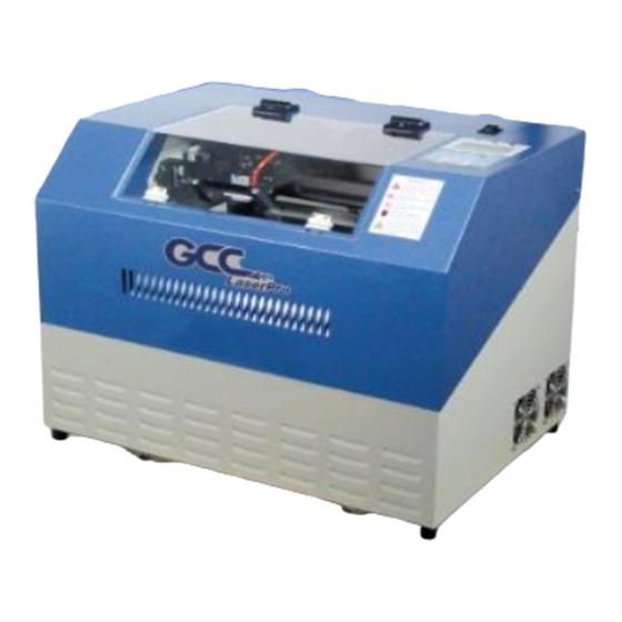
Chapter II - Mechanical Overview Please take some time to familiarize yourself with this section regarding the mechanical overview of the LaserPro VENUS. 2.1 Front View Power Switch Control Panel Top Door 2.2 Rear View Air Assist Valve Exhaust Port Power Inlet Laser Access Panel Ethernet Port... -
Page 12: Internal View
2.3 Internal View Laser Carriage Stamp Jig Slot 2.4 Focal Lens and Manual Focus Gauge There are four options of focal lens size, the smaller one will get smaller spot size, thus detailed engraving result, while the bigger lens with bigger spot size is good for cutting application. Focal Lens Focal Lens Manual Focus... - Page 13 Lens Carriage Assembly: Manual Focus Gauge Insert to the hole of the holder for manual focusing Mirror Lens 2.0, 2.5 or 4.0 Slot position for Lens 1.5 only Manual Focus Auto Focus Gauge Holder - 13 - 232001280G(13)
-
Page 14: Chapter Iii - Setup And Installation
Chapter III - Setup and Installation 3.1 Machine Setup 3.1.1 Powering Up the Machine CAUTION Make sure both the LaserPro VENUS and computer are turned off before connecting either to a power source. 1) Connect the USB cable in the accessory box to the rear side of VENUS. 2) Connect the male end of the power cord to a quality surge protector and then connect the surge protector into a properly grounded outlet. -
Page 15: Peripherals Setup
3.1.3 Peripherals Setup Connect the fume ventilation system and air compressor to the laser system before starting laser processing. Follow the detailed instructions in section 6.1 and 6.2. Fume Ventilation System Seal Clamp 2” or 4” diameter Flexible hose 3.1.3 Connecting the Computer The LaserPro VENUS can communicate with a computer through a USB Port or LAN Port connection interface. -
Page 16: Networking Connectivity Setup
3.1.3.1 Networking Connectivity Setup GCC laser engraver is built-in with LAN port to enable multiple laser engravers to be operated by one PC and multiple PCs to share a single unit of laser engraver. Follow the setup instructions below. Here use LaserPro Spirit GLS laser system as illustration. Step 1. - Page 17 - 17 - 232001280G(13)
- Page 18 - 18 - 232001280G(13)
-
Page 19: Ethernet Connectivity Setup
3.1.3.2 Ethernet Connectivity Setup GCC laser engraver is built-in with LAN port to transmit data from PC to laser engraver with ease and higher speed instead of USB port option. Step 1. Connect LAN cable to the LAN port of GCC laser engravers and turn on machine Step 2. - Page 20 Step 5. Go to <Control PanelNetwork and InternetNetwork Connections> of computer, right click mouse on the connected internet device, and choose <Properties> Step 6. Choose the <Internet Protocol Version 4(TCP/IPv4)> and click <Properties> to open up the setting window. - 20 - 232001280G(13)
- Page 21 Step 7. Enter the IP address and Subnet mask setting values, and choose <OK> Note the IP address 192.168.3.X (X value can be 1~255, while can’t be the same number as machine control panel setting in step 4) - 21 - 232001280G(13)
- Page 22 Step 8. Go to <Control Panel> <Device and Printers> of computer and right click on the laser machine printer, choose <Printer Properties>. Step 9. Select <Add Pot> under Ports tab, and follow the instruction to enter the TCP/IP information in laser machine’s control panel in step 4. - 22 - 232001280G(13)
- Page 23 - 23 - 232001280G(13)
- Page 24 - 24 - 232001280G(13)
- Page 25 Troubleshooting While users configure the Ethernet setting precisely with DHCP = OFF (assign the machine a static IP) referring to the manual, sometimes the communication might still not be able to work, at this time you can refer to below actions to have a basic troubleshooting with IT technician. Verify the IP addresses you are using to see if they are valid.
- Page 26 Command line mode window Type “ping x.x.x.x –t” after the prompt symbol, (x.x.x.x is the IP address you set on the laser machine, ie: 192.168.100.101)., press “Enter” to run the “Ping” tool. If the communication is OK between your PC and Laser machine, you will see reply from the destination IP.
- Page 27 Diagnostics a. For cases the communication is not ok (can’t get response, just have “Request timed out” from destination IP), you can look for two PC/Laptops which are original set in the LAN environment and work ok (they can get normal response from each other by the command “PING”), note down the TCP/IP configurations by running “ipconfig”...
-
Page 28: Graphics Software Setup
of GCC laser is normal, it should be something wrong in the LAN environment , ask the administrator of the LAN to solve the problem. 3.2 Graphics Software Setup The LaserPro VENUS is compatible with graphics software that can output HPGL commands, such as CorelDraw, Adobe Photoshop, AutoCAD, Illustrator etc. -
Page 29: Installation Of The Laserpro Print Driver
3.2.2 Installation of the LaserPro Print Driver 1) Insert the LaserPro CD. 2) From the auto run menu, select VENUS LaserPro Driver to start the LaserPro Print Driver installation. 3) At the Local or Network Printer page, select <Local printer attached to this computer>, then click Next to continue. -
Page 30: Parallels Desktops For Mac Os Users
3.2.3 Parallels Desktops for MAC OS Users MAC users can use GCC LaserPro machines by purchasing the Parallels Desktop software which allows you to install Windows OS in MAC computers and run Windows based software under MAC computer and output with GCC print driver. 1) Purchase Parallels Desktops on its official website. - Page 31 3) Read Software License Agreement and press “Accept” to continue installation 4) Enter your Mac OS X User Name and Password then press “OK” - 31 - 232001280G(13)
- Page 32 5) Press “Active” 6) Press “OK” when activation is complete. 7) Register Parallels Desktop - 32 - 232001280G(13)
- Page 33 8) Press “Register” and “OK” to complete the installation of Parallels Desktop. 9) Open Parallels Desktop (in the Applications folder) then choose File → New 10) Press “Install Windows from DVD or image file” then press “continue” to install windows OS - 33 - 232001280G(13)
- Page 34 11) Select CD-ROM drive with the Windows installation CD 12) Enter the Windows OS product key 13) Select how you would like to run your Windows program. - 34 - 232001280G(13)
- Page 35 14) After the prior setting is complete the windows OS installation procedure will start automatically. 15) Windows OS installation is complete then you can refer to “4.2.5 Installation of the LaserPro Print Driver” to install GCC LaserPro Print Driver. 16) Install the AP that you want to use after the above installation is complete. - 35 - 232001280G(13)
-
Page 36: Using Adobe's Ap With Gcc Laserpro Machine
3.2.4 Using Adobe’s AP with GCC LaserPro machine The Adobe’s AP (e.g. Illustrator, Photoshop or Acrobat reader) processes files via its Advanced Printing Features; users should firstly deselect Enable Advance Printing Features; otherwise the machine is unable to recognize or read general files when uploaded. ... - Page 37 The click the Advanced tab, then deselect Enable Advanced Printing Features, now all files can be recognized and uploaded. - 37 - 232001280G(13)
- Page 38 File Transfer 1) Select your working object, and then at the upper toolbar please choose File Print. 2) At the print setup screen, at Print Preset please select Custom, and choose your printer (e.g. Spirit) - 38 - 232001280G(13)
- Page 39 3) Then click on the lower left tab of Setup to enter Preferences settings. 4) After all preferences are set, click Print to send file to the machine for print out. - 39 - 232001280G(13)
-
Page 40: Using Autodesk Inventor With Gcc Laserpro Machine
3.2.5 Using Autodesk Inventor with GCC LaserPro machine 1. Start drawing. 2. Delete border and title block by right clicking on sheet1 and selecting delete. - 40 - 232001280G(13) - Page 41 3. Set sheet size to match working area of engraver. Engraver working area can be found on the paper tab of the windows driver. 4. Start sketch. 5. Engraving a. Finish sketch. b. Right click on sketch and select properties. c.
- Page 42 6. Cutting a. Finish sketch. b. Right click on sketch and select properties. c. Line Type: Continuous d. Line Weight: .001 in. e. Set color to match one of the 16 colors available in the pen tab of the windows driver.
-
Page 43: Using Ecut Plug-In With Gcc Laser Machine
NOTE All objects created in one particular sketch will have the same properties meaning all will engrave or all will cut. If you would like to engrave and cut in the same job you will need at least two sketches, one with all the engravings and another with all the cuts, to do so properly. -
Page 44: Chapter Iv - Operating The Laserpro Venus
Chapter IV - Operating the LaserPro VENUS Once you have installed the LaserPro USB Driver (USB connectivity only), LaserPro Print Driver, and have connected the LaserPro VENUS to your computer, you will need to familiarize yourself with the LaserPro VENUS’s control panel and LaserPro Print Driver. The print driver will be where you spend most of your time configuring specific laser parameters for your jobs, while the control panel will allow you to set repeat times, manipulate the file order, perform auto / manual focusing, configure the start point, and more. - Page 45 LED Indicator Lights LCD Display Screen Function Buttons Directional and Selection Buttons LED INDICATOR LIGHTS Three indicator lights on the LaserPro VENUS’s control panel are part of the system’s safety interlock system. DOOR - The door light will illuminate when any of the following doors or function is not working properly.
- Page 46 Directional ( / / /) - Four directional buttons allow you to navigate the selection cursor through the control panel menu and adjust the value of specific settings. In general, the / directional buttons cycle through the various selections, while the / directional buttons adjust the value of that particular selection.
-
Page 47: Graphic Control Panel Navigation Chart
4.1.3 Graphic Control Panel Navigation Chart Main Work Page Functions Page File Management Machine Setting Page Machine Information Page Page Select Lens System File Tune auto-focus Table Down Red Beam Vector Mode Save Position Carriage Free Command Mode File Save Mode LAN setup wizard Scaling Other... -
Page 48: Graphic Control Panel Function Pages
4.1.4 Graphic Control Panel Function Pages When the LaserPro VENUS is powered on, the machine will perform a series of safety checks and initializing routines. The LCD display screen will display the GCC copyright, LaserPro logo, and machine initialization pages before going to the main work page. Main Work Page The main work page is the page that the LaserPro VENUS will default to upon startup and will be the “home base”... - Page 49 Carriage / Work Table Adjustment Page ☼ navigating to this page: Main Work Page Press , , , , or F3 Carriage / Work Table Adjustment Page The Carriage / Work Table Adjustment Page allow you to manually increase and decrease the height of the work table (Z-axis).
- Page 50 Functions Page ☼ Navigating to this page: Main Work Page Press F4 Functions Page The Functions Page allows you to edit file management and machine settings. From this page, you will be able to access the File Management, Machine Setting, and Machine Information pages.
- Page 51 File Management Page ☼ Navigating to this page: Main Work Page Press F4 Functions Page Select <File Management> from the menu File Management Page The File Management Page allows you to manage the files that you have loaded onto the LaserPro VENUS.
- Page 52 Link/DLink Page ☼ Navigating to this page: Main Work Page Press F4 Functions Page Select <File Management> from the menu File Management Page Press F2 Link / DLink Page The Link/DLink Page allows you to set, arrange, and remove loaded jobs to and from a job queue for processing.
- Page 53 File Information Page ☼ Navigating to this page: Main Work Page Press F4 Functions Page Select <File Management> from the menu File Management Page Select a job file and press Enter File Information Page The File Information Page allows you to view the speed, power, DPI, and PPI settings of the selected job.
- Page 54 File Management Edit Page ☼ Navigating to this page: Main Work Page Press F4 Functions Page Select <File Management> from the menu File Management Page Select a job file and press Enter File Information Page Press F4 File Management Edit Page The File Management Edit Page allows choosing to modify your raster or vector settings for the selected job, as well as setting the number of times to repeatedly process the selected job (Repeat Num).
- Page 55 ☼ Navigating to this page: File Edit Vector Page Main Work Page Press F4 Functions Page Select <File Management> from the menu File Management Page Select a job file and press Enter File Information Page Press F4 File Management Edit Page Select <Vector Setting>...
- Page 56 Machine Setting Page ☼ Navigating to this page: Main Work Page Press F4 Functions Page Select <Machine Setting> from the menu Machine Setting Page The Machine Setting Page allows you to access and modify a variety of your machine settings, including: Set Lens, Tune Auto Focus, Set Table Down, Set Red Beam, Carriage Lock, Set Command Mode, Save Position, Flash Memory, Set File Save Mode, Set Vector Mode, Tune Image Power, Set Laser Wattage, Set Fine Mode, Other, Reset.
- Page 57 Set Lens Page ☼ Navigating to this page: Main Work Page Press F4 Functions Page Select <Machine Setting> from the menu Machine Setting Page Select <Set Lens> from the menu Set Lens Page The Set Lens Page allows you to modify the lens setting after you have changed to a different focal lens.
- Page 58 Tune Auto Focus Page ☼ Navigating to this page: Main Work Page Press F4 Functions Page Select <Machine Setting> from the menu Machine Setting Page Select <Tune Auto Focus> from the menu Tune Auto Focus Page The Tune Auto Focus Page allows you to manually set the default auto focus distance / vertical height of the worktable (Z-axis) for when the Auto Focus button is pushed.
- Page 59 ☼ Navigating to this page: Set Table Down Page Main Work Page Press F4 Functions Page Select <Machine Setting> from the menu Machine Setting Page Select <Set Table Down> from the menu Set Table Down Page The Set Table Down Page allows you to select whether or not the LaserPro VENUS displays a warning prompt at startup.
- Page 60 ☼ Navigating to this page: Set Red Beam Page Main Work Page Press F4 Functions Page Select <Machine Setting> from the menu Machine Setting Page Select <Set Red Beam> from the menu Set Red Beam Page The Set Beam Page allows you to turn on or off the red dot laser pointer on the laser carriage. Enabling this function will indicate the exact location where the laser will fire upon.
- Page 61 Set Vector Mode Page ☼ Navigating to this page: Main Work Page Press F4 Functions Page Select <Machine Setting> from the menu Machine Setting Page Select <Vector Mode> from the menu Vector Mode Page The Set Vector Mode Page allows you to adjust and balance vector mode’s quality and speed settings based on your specific job.
- Page 62 ☼ Navigating to this page: Save Position Page Main Work Page Press F4 Functions Page Select <Machine Setting> from the menu Machine Setting Page Select <Save Position > from the menu The Save Position Function allows you to save the current X-axis and Y-axis positions of the laser carriage and sets this position to be the origin for subsequent jobs.
- Page 63 ☼ Navigating to this page: Carriage Free Page Main Work Page Press F4 Functions Page Select <Machine Setting> from the menu Machine Setting Page Select <Carriage Free> from the menu Carriage Lock Page The Carriage Lock Page allows you to set whether the laser carriage is locked or free. If the Carriage Free setting is set to <YES>, then you will be able to manually move the laser carriage along the X and Y axis by hand with the top door open.
- Page 64 ☼ Navigating to this page: Set Command Mode Page Main Work Page Press F4 Functions Page Select <Machine Setting> from the menu Machine Setting Page Select <Set Command Mode > from the menu Set Command Mode Page The Set Command Mode Page allows you to configure vector settings when outputting in Default or HPGL mode.
- Page 65 ☼ Navigating to this page: File Save Page Main Work Page Press F4 Functions Page Select <Machine Setting> from the menu Machine Setting Page Select <File Save> from the menu Set File Save Mode Page The Set File Save Mode Page allows you to set whether or not the LaserPro VENUS automatically deletes each job file after processing.
- Page 66 ☼ Navigating to this page: LAN Setup Wizard Page Main Work Page Press F4 Functions Page Select <Machine Setting> from the menu Machine Setting Page Select <LAN Setup Wizard > from the menu LAN Setup Wizard Page The LAN Setup Wizard Page allows you to connect the laser machine with ethernet to transmit files from computer to laser machine for processing jobs.
- Page 67 ☼ Navigating to this page: Scaling Page Main Work Page Press F4 Functions Page Select <Machine Setting> from the menu Machine Setting Page Select <Scaling> from the menu Scaling Page The Scaling Page allows you to fine tune the laser machine output scale to precisely fit the original graphic file design scale when precision output is requried to your application.
- Page 68 ☼ Navigating to this page: Other Page Main Work Page Press F4 Functions Page Select <Machine Setting> from the menu Machine Setting Page Select <Other> from the menu Other Page The Other Page allows you to change various settings relating to the control panel. The Language setting will allow changing available languages displayed by the control panel.
- Page 69 Reset Page ☼ Navigating to this page: Main Work Page Press F4 Functions Page Select <Machine Setting> from the menu Machine Setting Page Select <Reset> from the menu Reset Page The Reset Page will restore machine settings back to factory default. Press ENTER to confirm the change, and restart the machine.
- Page 70 ☼ Navigating to this page: Machine Information Page Main Work Page Press F4 Functions Page Select <Machine Information> from the menu Machine Information Page The Machine Information Page allows you to view information regarding the system such as the GCC logo, machine name, firmware version, and other information.
-
Page 71: The Laserpro Venus Print Driver
4.2 The LaserPro VENUS Print Driver With the LaserPro VENUS print driver successfully installed, you will need to adjust the printer and page size default settings before you can begin editing and completing jobs. By doing so, you will be setting the work area in your graphics software to match the LaserPro VENUS’s worktable area. -
Page 72: Color Management
Corel Draw Example (Page Setup and Orientation) The following is an example of how to set the Page Setup and Orientation in the graphics software. CorelDraw is the designated graphics software used for this example. For other graphics software, you will need to access the corresponding Page Setup page. - Page 73 Disable Color Management or set Color Management to Off. Corel Draw Example (Color Management) The following is an example of how to properly disable Color Management in the graphics software. CorelDraw is the designated graphics software used for this example. For other graphics software, you will need to access the corresponding Color Management page.
-
Page 74: Using The Laserpro Venus Print Driver
4.2.3 Using the LaserPro VENUS Print Driver Now after you have properly set the Page and Layout and Color Management of your graphics software, you are ready to configure the details of your actual job through the LaserPro VENUS Print Driver. The LaserPro VENUS print driver allows you to adjust your cutting options. -
Page 75: Laserpro Venus Print Driver >> Option Page
The following sections describe the specific functions for each of the settings found in the LaserPro VENUS Print Driver. If you are new to laser cutting, it is recommended that you first familiarize yourself with the general principals of the laser process in Section 6, especially the Vector Cutting concepts. - Page 76 Black & White: Select this mode when using clipart images or drawings with several colors, shades of gray, or many outlines. This mode outputs in a method similar to that of a black and white laser printer. The GCC LaserPro print driver will interpret colored and shaded areas as 256-level shades of gray by producing a halftone effect while engraving.
- Page 77 3D Mode: 3D Mode allows the naked eyes to visualize the curvatures of the 3D effect by applying 2 00 grayscale power level technology to create different depth of engraving. Stamp Mode: The stamp mode is one of the more dynamic functions of the LaserPro laser engravers by applying 200 power leve to create different steps.
- Page 78 DPI Setting 300* 600* 1000 1500 Actual 1016 1524 NOTE Outputting a full-table (11.8”x8.26") job using 300 or 600 DPI will result in a truncation error; this is due to the large differences in set DPI vs. actual DPI output for those two particular DPI settings.
- Page 79 Print Immediately (Options Page) [DEFAULT SETTING: Unselected] Checking this will instruct the LaserPro VENUS to immediately begin the laser engraving process, when you select Print from your graphic software program. If Print Immediately is not checked, then selecting Print will transfer the job file to the LaserPr o VENUS system and will need to be initialized from the LaserPro VENUS control panel.
- Page 80 A filename will be prompted. After entering the filename and pressing <ok>, the Preview screen will be shown. - 80 - 232001280G(13)
- Page 81 The output file can be previewed and an estimated working time of the job is also displayed. The working time is only estimation which might be slightly different from the actual working time. File Function (Options Page) The file function section allows you to manage various laser parameters. This section is useful when performing duplicate jobs on a variety of objects, allowing you to save your frequently used laser parameters and load them in the future.
- Page 82 - 82 - 232001280G(13)
-
Page 83: Venus Print Driver >> Pen Page
4.2.3.2 VENUS Print Driver >> Pen Page The LaserPro VENUS incorporates the use of 16 different colors to represent 16 different laser power and speed settings when cutting. These colors are referred to as “Pens”. Think of each pen as a designated laser setting, rather than as a color. - Page 84 NOTE The VENUS print driver cannot store more than 16 pen colors or different laser parameter settings per file. Speed (Pen Page) [DEFAULT SETTING: 50] The speed slider controls the laser’s speed during operation (engraving speed) with settings ranging from 0.1 – 100%.Only when moving in straight line with enough distance, the carriage can achieve 100% speed.
- Page 85 PPI (Pen Page) [DEFAULT SETTING: 400] PPI (pulses-per-inch) represents the pulsing frequency of the laser pulse (fire) numbers within an inch exclusive for vector cutting. Higher PPI settings may cause more melting, burning or charring on the edges when cutting. Lower PPI settings may reduce this effect, but may result in a serrated looking edge. If you drag the PPI slider to the maximum, the value will change to X.
- Page 86 4.2.3.3 VENUS Print Driver >> Advance Page Scaling (Advance Page) [DEFAULT SETTING: 0] In some cases you may find a slight output inaccuracy in the actual output compared to what you have set in the computer. This margin of error or offset is extremely small (approximately 1/300). What this means that there may be a 1-unit offset for every 300 unit increments.
- Page 87 • Relative: This mode sets the current laser head position to correspond to the origin (top left) position of the graphic software. Therefore, the laser head will process the job from its current position relative to its setting in the graphics software. •...
- Page 88 These selections allow you to control the direction in which the system processes an engraved image. • Top To Bottom: Selecting this will force the system to process the current task by moving the lens carriage from the top to the bottom of the image (rear end to front end of the work table). •...
- Page 89 • Normal: This selection will not apply any special advanced vector function to your job. This is the default Vector Function setting. • All Raster Output: This selection will instruct the print driver to process your entire image as a raster engraving.
- Page 90 cutting formultiple layers adhesive materials, such as lettering vinyl, heat transfer film, and twill film. This function allows allocating different parameters for corresponding decal layer numbers to do die cut (cut through media) for the unwanted parts, and kiss-cut (half cut) for the kept material parts, after the laser cutting, users can just peel off the materials to get rid of waste parts.
- Page 91 This setting allows you to improve the cutting quality at the expense of speed. We recommend you enable this function when cutting thicker materials. Use Cluster (Advanced Page) [DEFAULT SETTING: Unselected] This setting allows you to change how the Spirit interprets and processes individual / independent areas of an image in order to minimize job-processing times.
- Page 92 - 92 - 232001280G(13)
-
Page 93: Venus Print Driver >> Paper Page
4.2.3.3 VENUS Print Driver >> Paper Page Paper Size (Paper Page) The paper size represents your total work area. Ensure that the paper size is never set greater than the VENUS’s worktable area of 11.8” x 8.26” (300mm x 210mm). The X value represents the length and the Y value represents the width. -
Page 94: Venus Print Driver >> Language Page
image tuning to a positive value. The further the protruding lines are from the square’s ideal edge, the larger you will need to set the Image Tuning value to compensate. Square’s Left Edge Square’s Right Edge The following is an example that has the proper image tuning, and demonstrates this significance when engraving fine, small, intricate text. -
Page 95: Venus Print Driver >> Raster Page
4.2.3.5 VENUS Print Driver >> Raster Page NOTE The Raster Page is only available when Black & White Mode Setting is selected from the Options Page, this page offers a number of advanced Raster Engraving output options. Contrast (Raster Page) [DEFAULT SETTING: 0] This provides a quick and easy way to immediately adjust the contrast of an engraved image. - Page 96 ○ Pattern Type: Dot, Bayer, Corner, 45 Degree [DEFAULT SETTING: Dot] Each pattern type uses a different shape and arrangement of dots to compose the shading effect of a raster image. The following diagram is an example of the raster effects when using the different pattern types.
- Page 97 Each diffusion type presents the shade of image as different spread halftones instead of dots to compose a raster image. The following diagram is an example of the raster effects when using the different diffusion types. There is no “correct” or “best” setting when using the Raster options. The most appropriate settings will be based on a variety of factors: your design, the material you are engraving on, and the results you wish to achieve, etc.
- Page 98 Bridge: contact area of the stamp Slope of ridge (shoulder level) Base of ridge (pitch) Pitch (Stamp Page) Your stamp will be a reversed image composed of engraved depressions and ridges. Think of these ridges as the “contact sections” of the stamp. If the ridges of these contact sections are too thin, they may break.
-
Page 99: Chapter V - Cutting Techniques
Chapter V - Cutting Techniques 5.1 Raster Cutting A laser engraver can process text, scanned image, digital picture, or design by “laser firing” grids / dots of individual pixels into a raster image. Think of this as simply “printing ” your job onto any particular material. -
Page 100: Raster And Vector
Below is an example of how to prep an area (in this case, we will use a section of text) fo r vector cutting. CorelDRAW will be used as the selected graphics software. With the text function, create a string of characters and select those characters by clicking on the text. -
Page 101: Modify Image Settings Of A Picture For Better Engraving Qulaity
5.4 Modify Image Settings of a Picture for Better Engraving Qulaity Connect your digital camera to the computer by USB cable. Download the picture from the digital camera to the computer Select the picture that you want to engrave. Import the image from the folder where the picture is located by selecting File/Import - 101 - 232001280G(13) - Page 102 Convert the image to Bitmap by selecting the image and click on Bitmaps/Convert to Bitmap Change the Bitmap settings by setting “Color” to Grayscale (8-bit) and “Resolution” to 300 dpi and click OK. - 102 - 232001280G(13)
- Page 103 Finally, Invert the image by selecting Effects/Transform/Invert - 103 - 232001280G(13)
- Page 104 Now you are ready to output the modified image by clicking File/Print NOTE This instruction is a simple example for general use. There are many tips and tricks to achieve a good engraving quality. It takes a lot of practice and experience to achieve a good engraving quality.
-
Page 105: Chapter Vi - Optional Items
Chapter VI - Optional Items When purchasing the LaserPro VENUS from your local authorized GCC distributor, you will be provided a chance to purchase optional items to enhance your experience with your system. If anytime after the purchase of your VENUS, would you like to purchase any optional item, please contact your local authorized GCC distributor. -
Page 106: Air Compressor
Exhaust Ventilation System Seal Clamp 2” Flexible hose 6.2 Air Compressor Specifically designed for laser engravers, the air compressor utilizes an oil-free diaphragm. The air compressor helps eliminate harmful and potentially damaging moisture from the laser optics, maximizing laser optic life. In addition the air compressor provides the optimal air flow to the SmartAIR nozzles to minimize flaming, suppress working temperatures, and blow away dust and particle byproducts generated from the laser process. - Page 107 INSTALLATION: 1) Remove the plugs on the air compressor to expose the air inlets. 2) Fasten the included air tube fastener valve to the outgoing air inlet (indicated by 2a) and the air filter into the ingoing air inlet (indicated by 2b). Plugs Plugs 3) Connect a ¼”...
- Page 108 Air Flow Regulator: Air Tube Fastener Turn Clockwise to increase airflow Turn Counter- Clockwise to Air Tube decrease Connector airflow Congratulations, you have finished setting up the air compressor. OPERATION: 1) Switch on the air compressor unit and make sure that the airflow regulator on the air assist valve is opened (turn clockwise to increase the airflow, counter-clockwise to decrease the airflow).
-
Page 109: Chapter Vii Basic Maintenance
Chapter VII Basic Maintenance Keeping your LaserPro VENUS clean and well maintained will ensure quality output, consistent reliability, and extended product life. Smoke, dust or residue build-up inside the laser system or the mechanical components can cause a reduction in the laser power, irregularities in the motion system, reduced product life cycle, and a host of other avoidable problems. -
Page 110: Maintaining The Worktable And Motion System
7.2 Maintaining the Worktable and Motion System 7.2.1 Accessing the Worktable and Motion System Remove the screws of the top chassis of the machine and lift the top off. Utilize the screws to hold the top cover 7.2.2 Cleaning the Worktable and Motion System 7.2.2.1 Cleaning the Worktable and Motion System Clean the working table and the motion system on weekly basis through the following steps: 1) Turn the power off and unplug the laser machine before cleaning. -
Page 111: Lubrication Of The X / Y Rails
Please clean the AutoFocus pin each time after completing the engraved job to make sure the AutoFocus pin is free to move. 7.2.2.2 Lubrication of the X / Y Rails In order to keep the motion system running smoothly, the X / Y rails of the motion system will need lubrication on a weekly basis. - Page 112 Thumbscrew Thumbscrew Thumbscrew 3) Clean the lens in the proper manner. 4) Re-install the mirror after cleaning. 5) Tighten the thumbscrew. 6) Replace and secure the outer access panel. Mirror 2, 3, 4 These mirrors are located in the worktable area of the LaserPro VENUS. Mirror 2 Mirror 3 Mirror 4...
- Page 113 Mirror 2 1) Unscrew and remove the black dust cover covering mirror 2. 2) Unscrew the thumbscrew holding mirror 2 in place. 3) Clean the lens in the proper manner. 4) Re-install mirror 2 after cleaning. 5) Tighten the thumbscrew. 6) Replace and secure the black dust cover.
-
Page 114: Cleaning The Mirrors
7.3.2 Cleaning the Mirrors After you have removed each mirror, you will want to inspect each mirror for scratches, smoke residue, or debris. If any residue or debris is present, use the following steps to clean the mirror. 1) Hold the mirror with the reflective side up, without touching the reflective side of the mirror (DO NOT apply any finger pressure or any other cleaning solutions to the mirror surface). - Page 115 3) Clean the focal lens with a cotton swab and lens cleaner solution. Be sure to clean both sides of the focal lens (DO NOT apply any finger pressure or other cleaning solutions to the lens surface). 4) After cleaning, use a cotton swab to gently dry the focal lens and lens cover. Please clean the AutoFocus pin each time after completing the engraved job to make sure the AutoFocus pin is free to move.
-
Page 116: Chapter Viii - Basic Troubleshooting
Chapter VIII - Basic Troubleshooting Quality Problems Check focal length setting under F4 function key-> Machine Setting-> Set Focus Lens to see if it matches the type of the lens installed. Check if the focal Lens is installed correctly or if focal Lens is not fixed properly. ... -
Page 117: Glossary
Chapter IX- Appendix 9.1 Glossary Color Fill – Term within the awards and engraving industry used to describe the variety of techniques used to add color or contrast to engraving. DPI – Dots Per Inch or Pixels Per Inch. The resolution of an image as defined by the amount of dots/pixels included in an inch. -
Page 118: Laserpro Venus Specification Sheet
9.2 LaserPro VENUS Specification Sheet Venus II VII-12 Laser Source Sealed CO Laser Cooling Air-cooled, Operating environment temperature 15 - 30 C (60 - 86 Work Area 11.8 x8.2 in. (300mm x 210 mm) Max. Part Size (W x L x H) 14.2 x 11.8 x 2.8 in.
Need help?
Do you have a question about the LaserPro Venus II and is the answer not in the manual?
Questions and answers