Advertisement
Quick Links
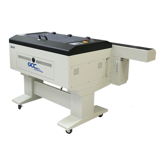
User Guide - X252 & X380
s I
u s
e
4
2021
This document is designed as a quick step training guide and NOT
a manual. It should therefore be read in
conjunction with the manufacture
' r
s user manual.
This can be found on the GCC CD ROM, supplied with your
machine.
W
e strongly recommend that you read and/or print out that manual.
Advertisement

Related Manuals for GCC Technologies LaserPro X252


Summary of Contents for GCC Technologies LaserPro X252
- Page 1 User Guide - X252 & X380 2021 This document is designed as a quick step training guide and NOT a manual. It should therefore be read in conjunction with the manufacture ’ r s user manual. This can be found on the GCC CD ROM, supplied with your machine.
- Page 2 WORKSHOP MAINTENANCE SERVICES WF-Education has a comprehensive sevice and maintenance package ensuring your workshop equipment will last for future years. Trained engineers will service and maintain the installed machinery and carry out all the obligatory fume and dust extraction tests (LEV). Please contact our Head Office for further details of this service.
- Page 3 Page 4......Warranty Information 5......General Laser Information 6.
-
Page 4: Warranty Information
Warranty Information Your WF-Education Group Laser and tube are warrantied against manufacturing defects for a period of 2 years from the date of purchase, this warranty excludes any consumables items. Subject to the terms and conditions listed below, the warranty will provide for the on-site repair of the laser, or any component thereof, which is identified as faulty or below standard, or is a result of inferior workmanship or materials. -
Page 5: General Laser Information
General Laser Information What is LASER an Abbreviation of? LASER stands for Light Amplification by Stimulated Emission of Radiation. How Does a Laser Work? A CO laser works by exciting the molecules of a carbon dioxide gas mixture. C0 lasers are not powerful enough to mark or cut metal. The laser beam is focussed through a lens and is so intensive that the beam can vaporise a wide range of materials. - Page 6 What Materials Can Be Used? Consult Your MSDS WF-Education always recommends that you consult your MSDS (Material Safety Data Sheet) supplied with your material, even if the material is listed below as acceptable to be used with your laser. This is because certain materials may contain different chemicals/substances from the manufacturing process. The user is responsible at all times for the health and safety of themselves and the people around the machine with regards to the chosen materials.
- Page 7 Risk Assessment for Schools The following risk assessment is provided to cover the use of laser cutters/engravers in schools to cut plastics, rubber, wood, card and textiles as an example of CAD/CAM. It has been formatted in the style of CLEAPSS. Please note that all of the laser cutters supplied by Technology Supplies are Class 3a lasers (Class 1 without the red beam pointer) not Class 4.
- Page 8 Immediate Remedial Measures Burns The beam may produce a deep cut in tissue with little bleeding because the wound is immediately cauterised. Obtain specialist treatment. Blinding There is no immediate remedial measure. High Voltage Taking care for your own safety, break contact by switching off or pulling out the plug. If it is necessary to move the casualty without switching off the supply/use a broom handle or wooden window pole or wear rubber gloves.
-
Page 9: General Maintenance
General Maintenance The lens, mirrors, bed, auto-focus gauge and runners must be cleaned before use or on a weekly basis to ensure correct operation of the laser, and the fume extractor filters should be replaced as required. If you cut and/or engrave mainly on wood, MDF and plywood then more fumes are produced therefore the lens, mirrors, will need cleaning much more frequently, (Please refer to the maintenance log on page 57). - Page 10 Location of the X252/X380 Mirrors Accessing Mirror 1 Step 1. To access mirror 1 you will need to remove the screws from the tube access panel. Accessing this panel will reveal the black casing which contains mirror #1. N.B. PLEASE MAKE SURE THE LASER MACHINE IS DISCONNECTED FROM THE MAINS POWER BEFORE OPENING THE TUBE ACCESS PANEL! Black Casing Remove these three screws to open the laser tube access panel.
- Page 11 Step 4. With the dust cover removed you will be able to see 2 mirrors (A & B). Mirror A is the Red Beam mirror and only has to be cleaned if you can no longer see the red beam on the laser bed/material, as this mirror only bounces the red light beam NOT the laser cutting beam. The mirror labelled B is mirror number one which is the first of the three mirrors which the laser beam hits as it passes through the machine.
- Page 12 Releasing Mirror #2 (Mirror #3 on the X380) To release this mirror you need to loosen off the two screws as shown below and slide the mirror out. Ensure that the mirror is replaced correctly before reassembly. Loosen off these two screws to enable you to slide out the...
- Page 13 Correct Positioning of Mirror #3 (Mirror #4 on the X380) and the 2 Inch Lens A common problem for first time users is that after cleaning they insert the mirror and the lens into the wrong locations. Please see pictures below explaining how to locate these parts correctly.
-
Page 14: Cleaning The Mirrors And Lens
Cleaning The Mirrors And Lens Cleaning the Mirrors The mirrors should be cleaned on a weekly basis or daily basis depending upon usage. The mirrors are gold faced and can easily be damaged if not handled carefully. The mirrors can blister and crack if they are not kept clean. When cleaning always put the mirrors with the gold face uppermost and only use the proper cleaning materials. (See Photo in step 1). - Page 15 Lens Cleaning The lens should be checked often and cleaned, possibly hourly especially if you are processing materials which contain resin such as woods, MDF and ply. Squeeze some lens cleaning fluid onto a cotton swab and gently rub in a spiral motion from the centre outwards on both sides of the lens. If necessary dry the lens with a clean dry swab.
- Page 16 Water Chiller Information W W h h a a t t Ty y p p e e o o f f Wat t e e r r Do o e e s s t t h h e e Ch h i i l l l l e e r r Req q u u i i r r e e ? ? You should only use de-ionised water in the chiller unit.
- Page 17 Laser Driver Installation The latest laser printer driver is usually in the form of an executable installation program and therefore only requires double clicking to install. However sometimes the driver can contain a directory of 9 files, including an inf file in which case please follow the step by step installation on page 18. Windows 10 does not allow the installation of unsigned drivers, please refer to page 17 for information on disabling this function and to boot around Windows start up.
- Page 18 Pre-Installation Setup for Windows 8/10 Pre-Installation for Windows 8/10 driver Many devices ship with unsigned drivers and 64-Bit versions of Windows require digitally signed drivers. Digitally signed drivers include an electronic fingerprint that indicates which company the driver was produced by, as well as an indication as to whether the driver has been modified since the company released it. The laser drivers are NOT digitally signed and therefore may require this workaround.
-
Page 19: Installation Complete
Installing Windows 7/8 USB driver Driver Installation For Windows 7-10 Installing Windows 7 Driver (inf file) Step 1. Insert the LaserPro driver CD supplied with your laser cutter and close the auto disc startup feature. Step 2. Go to the Start menu within Windows 7 and select Devices and Printers. Then select Add a Printer from the top toolbar. Step 3. - Page 20 Recommended Driver Setup This simple step by step guide is provided to set your machine up for best use within the education sector. By following the guide you will be running your printer driver in conjunction with the recommendations of WF-Education Group. The settings will reduce users experiencing issues with educational specific software (such as 2D Design). Please perform this setup under FULL ADMINISTRATION RIGHTS.
- Page 21 Step 6. Go to the other Advanced tab. Here you can set the image output direction to Bottom to Top which will engrave your project in the optimum direction. Enhanced Vector. This will Position Mode. We usually produce a cleaner vector cut recommend RELATIVE mode but will considerably slow by default as this allows you...
- Page 22 Techsoft 2D Design Version 2 Setup If you are using Techsoft 2D Design Version 2 to output your designs to the laser cutter then you will need to complete the following setup to ensure that communication can be established between the software and the laser cutter. Please perform this setup under Full Administration Rights. Note: If you are unsure whether or not you are operating from Version 2 of Techsoft 2D Design then simply open up 2D Design and select ‘help’...
- Page 23 Step 3 . In the top right hand corner of the settings window will be a section called ‘ Windows Printer Driver’ . Within this section you will need to change both Vector and Bitmap Modes mode 1 from mode 2 to Step 4.
- Page 24 Example Project Using 2D Design This section will run through how we recommend you use 2D Design with your laser cutter. We shall use a key fob for this project as this is a simple design but will also cover how you should address larger more complicated projects. Use a systematic approach for setting up the laser, software and printer drivers. We will cover: How to set up your page size in 2D Design so that it matches the size of you material in the laser cutter.
- Page 25 Step 3. Select the fourth option down in this new Window called “User Defined” . Once you tick this box it will enable you to input your X and Y axis. Note: You can use the X and Y rulers in the laser cutter for the material measurements. Step 4 .
- Page 26 How To Assign Colours In 2D Design How to assign colours in 2D Design This step by step section of the guide will run through how to assign the custom colours in 2D Design to create a print order on the laser cutter. This will determine if a section of the design is engraved, scorn or cut out.
- Page 27 Step 2 . Go to the Colour button located directly to the right of the Line button in 2D Design and select it with your mouse. Step 3. Once selected you will see the below box open up on the screen. You will see that the first three of the custom colours are in the recommended order.
- Page 28 How to Engrave a Photograph With Version 2 of 2D Design you will be able to engrave bitmaps, this advanced section will show you the extra steps that will need to be taken to engrave a bitmap. Step 1. Firstly, you will need to import your photograph/bitmap into 2D Design. To do this go to ‘File’...
- Page 29 Once you have followed this process your bitmap will now be a greyscale image (see below). Step 3 . Follow your normal setup ie. setting the colours and page size in 2D Design. Setup the printer driver the same as you normally would but in the Options tab when you select the greyscale engrave mode called Black and White a new tab called Raster will appear in the print properties.
- Page 30 CorelDraw Setup for Lasers When you first install CorelDraw the default settings in the program can cause operational issues for the laser, please make sure that you update the software. These issues are, the default line thickness is 0.2mm which means that the laser will always engrave your work and will not perform the vector functions correctly. The colour palette that you use to setup your project cut order will not match up with the printer driver colours and finally the program will not let you engrave a photograph and cut at the same time.
- Page 31 Step 2. On the left side of the program select the pen tip icon, then select the same icon from the menu that appears. If the pen icon is not present, please press F12 on the keyboard. Step 3. From the pop up window that appears make sure that the Graphic tick box is selected and then click ok. Page 31...
- Page 32 Step 4. Select the drop down arrow from the width box, then select ‘hairline’ then click OK. Step 5. Select ‘Tools’ from the top toolbar then click ‘Save Settings As Default’. This will now ensure that the software will communicate the correct line thickness to the laser cutter.
- Page 33 Step 6. To get the CorelDRAW colour palette to match that of the laser cutter click ‘Tools’ on the top toolbar and then ‘Color Management’ then across to ‘Default Settings’. Step 7. From the window that opens up select the ‘Presets’ drop down menu and from the list select the option ‘Simulate Color Management Off’ then Click OK. You will now notice that the CorelDRAW colour palette has changed.
- Page 34 Step 8. To change the settings to allow a photograph to be engraved and cut out at the same time, you will firstly need to draw something on the design page. This will enable you to select the ‘Print’ option from the ‘File’ menu on the top toolbar. Draw anything on the page.
- Page 35 Step 10. From the ‘Color Conversions Preformed by’ drop down menu select your laser cutter then click ‘Apply’ then select ‘Cancel’. Step 11. Finally go to ‘Tools’ on the top toolbar and select ‘Save Settings As Default’. CorelDRAW will now be setup to function correctly with your laser cutter. Page 35...
- Page 36 Example Project Using CorelDRAW This section will run through how we recommend you use CorelDRAW with your laser cutter. We shall use a key fob as our project as this is a simple design but will also cover how you should address larger more complicated projects. Use a systematic approach for setting up the laser, software and printer drivers. We will cover: How to set up your page size in CorelDRAW so that it matches the size of you material in the laser cutter.
- Page 37 Step 2. Once you press ENTER your CorelDraw page size will now adjust and represent the size of the material in the laser cutter. Assigning the Colours in CorelDraw This step by step section of the guide will run through how to assign the Custom Colours in Coreldraw to create a print order for the laser cutter.
- Page 38 Step 1. After you have designed or loaded your project, you will need to select the parts of the design you want to assign a particular colour to. To do this click the left mouse button on the part you are wanting to select. You will now see eight square sections located around a cross to indicate that the part is selected. Step 2.
- Page 39 How to Engrave a Photograph Using CorelDraw This advanced section will show you the extra steps that will need to be taken to engrave a photograph/bitmap image using your CorelDraw software. Step 1. With your CorelDraw page open go to ‘File’ on the top toolbar then select ‘Import’ from the drop down menu. Step 2.
- Page 40 Step 3. Once you have imported your image on to the page select the image and go to ‘Bitmaps’ on the top toolbar. From the drop down menu that now appears select the first option ‘Convert to Bitmap’. Step 4. A pop up window will appear on screen. From the drop down menu select the ‘Colour Mode’ section and choose the ‘Grayscale (8 bit)’ option then click ‘OK’. Page 40...
- Page 41 You will now see that your image has changed to a greyscale image. Scale the image to the desired size then proceed to ‘File’ on the top toolbar and select ‘Print’. Step 5. Follow your normal setup ie. setting the colours and page size in CorelDRAW X7. Setup the printer driver the same as you normally would but when you select the options tab select the greyscale engrave mode called Black and White and a new tab called Raster will appear in the print properties.
-
Page 42: Setting Up The Machine
Setting Up the Machine Step 1. Ensure that all the cables are correctly connected to the laser cutter, i.e you have the power and correct data cable linking the laser cutter to your computer. If this is OK, turn on the laser cutter at the rocker power switch. Step 2. - Page 43 Step 4. Make sure that the Auto focus probe is located over solid material . i.e; when the auto focus button is pressed the probe will not pass through the grid bed or the material. Auto Focus Probe Step 5. Press the Auto Focus button on the control panel (Shown below), this will raise the material to contact the auto focus probe which will in turn lower the material ensuring that the lens inside the head is at its...
- Page 44 Setting Up The Printer Driver To Send A File This section will cover how to set up your printer driver, input your power and speed settings, assign engrave modes and set up your paper size to match the design page in 2D Design. Step 1.
- Page 45 Step 3. (Tab ) The first tab shown is the ‘Options’ tab. Here you will need to select which type of engrave mode you would like to use with your project. Once you have selected the relevant engrave mode click on the next tab. Brief explanation Of The Engrave Modes Black and White.
- Page 46 Step 4. (Tab ) Pen. The second tab you come to is called This is where you will set up the power and speed that you would like the laser to run at for the different materials (refer to the Engrave and Cut settings at the back of this manual). To input the settings simply move the slider bars left or right for the required settings.
- Page 47 Step 5. (Tab ) Advanced The third tab called is where you can set which position mode the laser starts from, which Y axis direction the laser will engrave in and whether you will use enhanced vector with a job. Position Mode.
- Page 48 Step 6. (Tab ) Paper The fourth tab called is where you setup the printer driver paper size to match the size of your design page in your design software. Please note that the paper size is not required to be changed as the installed laser driver will automatically set this paper size to the laser bed size, which is the maximum working area.
- Page 49 Using The Rotary Attachment The rotary attachment is an optional item for the GCC Laser cutters. It adds a 4th axis that provides the capability of engraving onto cylindrical objects suchs as glasses, vases and tubes. The unit can handle objects up to the maximum lenght of 450mm and has a padded rubber drive wheel and a clamp for holding and rotating the workpiece. The wheel has a maximum diameter of 94mm, however the maximum diameter of the loaded object can be up to 180mm with a limited loading weights of 7kg.
- Page 50 Step 4. Plug the serial lead connection into the port located in the inside front of the laser figure 1 . Then you can screw the rotary fixture to the laser bed via the two screw holes at the right hand side of the rotary attachment as shown in figure 2. Fig 1 Note: This photo is from the back of the laser to give a clear view of the port.
- Page 51 Step 6. Turn the power to the laser back The laser will now go through a different initialisation process which will involve the laser bed lowering to activate the Lower Trip Switch. The laser head will move along it’s X and Y axis before centring over the cone on the rotary attachment, the Y axis will now be locked. The left and right directional arrows on the control panel will move the laser head along the X axis and the up and down arrows will now rotate the cone on the rotary attachment.
- Page 52 Step 10. Highest Using the control panel on the laser cutter, move the laser head over the point of your object and press the auto focus button. This will focus the laser to the object. Step 11. Once you have auto focussed the laser you will now need to raise the auto focus probe from the laser head to allow maximum clearance between the object and the laser head.
- Page 53 Page Setup for Rotary Attachment Using CorelDRAW This section will take you through how to setup your page in CorelDraw for use with your rotary attachment. Step 1. Firstly, you will need to measure the length and width of your object. Step 2.
- Page 54 Printer Driver Setup for Rotary Attachment Useful Rotary Attachment Information The smallest diameter that can be fitted to the rubber cone pad is 56mm. The unit rotates in a clockwise direction (*1) when viewed from the right hand end The largest diameter that can be fitted to the rubber cone pad is 94mm. of the laser (the control panel end) (*2) The maximum diameter of object that can be engraved is 180mm.
- Page 55 Manual Focus Probe At some point during the life of your laser cutter, it may be necessary to use the manual focus probe to set the correct distance between the cutting head and the material. This probe is located in the white accessories box originally supplied with the laser cutter. This probe often used when the auto focus probe on a laser cutter is either faulty or damaged, the manual probe will enable you to carry on working with the machine .
- Page 56 Useful Control Panel Commands Useful control panel commands: (from the main menu) Deleting a file: F4, Enter, (then press either) F3 to delete a single file or F4 to delete all files The picture below shows the laser main menu screen. From this screen you will be able to Sending the laser head to HOME.
- Page 57 How to Enable/Disable the SMART Guard The SMART Guard is an optional extra on our range of laser cutters and is a fire detection device that provides an early warning of potential fires in the laser cutter. The sensitivity of the SMART Guard can be adjusted between 1-9 seconds but on some applications such as wood cutting and glass engraving may still trigger the SMART Guard to be set off.
-
Page 58: Maintenance Log
Maintenance Log This maintenance log template sheet is provided for schools to correctly record ongoing maintenance. Cleaning your laser as per our recommendations will help ensure the machine operates efficently and will reduce the risk of needing an engineer’s visit. The maintenance schedule is a guideline as this will be dependant upon usage and material type. - Page 59 X252 & X380 Engrave Settings Note: ONLY These settings are to be used as a rough guideline as each individual laser tube can vary. Glass Correx Leather Acrylic Polypropylene Fabric Balsa Wood Laser Ply Thin Card Boxcard Lino Cork Speed 80w X252/X380 Power Speed...
- Page 60 X252/X380 Cut Settings Note: These settings are to be used as a rough guideline ONLY as each individual laser tube can vary. Acrylic 2mm Acrylic 3mm Acrylic 5mm Acrylic 12mm Acrylic 20mm Thin Card Balsa Speed 80w X252/X380 Power MDF 4mm MDF 6mm MDF 9mm MDF 12mm...
- Page 61 Personal Material Settings Sheet Material Speed Power Material Speed Power Material Speed Power Material Speed Power Material Speed Power Material Speed Power Page 61...
- Page 62 Laser Setup Check List Please refer to this section to aid you in setting up and running a job through the laser. Step 1. Carefully place your material onto the laser bed, manouver the auto focus probe (laser head) over the material, either using the direction keys or by hand and then press the auto focus button.
Need help?
Do you have a question about the LaserPro X252 and is the answer not in the manual?
Questions and answers