GCC Technologies X380 User Manual
Laser engraver/cutter
Hide thumbs
Also See for X380:
- User manual (78 pages) ,
- User manual (62 pages) ,
- Maintenance manual (109 pages)
Table of Contents
Advertisement
Advertisement
Table of Contents

Related Manuals for GCC Technologies X380


Summary of Contents for GCC Technologies X380
- Page 1 232001250G(06)
- Page 2 Dear Sir or Madam, Thank you for choosing GCC and the LaserPro X380 Series. You can be assured that this machine meets all of the highest safety standards while using technological innovations shared by no other laser cutter. The X380 is backed by GCC, a truly international company that is dedicated to helping your business grow.
-
Page 3: Table Of Contents
4.2.6 Parallels Desktops ..................... - 19 - 4.2.6 Using Inventor with GCC LaserPro machine ..........- 24 - Chapter V - Operating the LaserPro X380 ..................- 29 - 5.1 Using the Hardware ...................... - 29 - 5.1.1 Adjusting the LCD Display Screen’s Contrast Setting ........- 29 - 5.1.2 Graphic Control Panel Overview (Description) .......... - Page 4 5.2.3.1 LaserPro X380 Print Driver >> Option Page ............56 5.2.3.2 X380 Print Driver >> Pen Page ................. 58 5.2.3.3 X380 Print Driver >> Advance Page ................ 61 5.2.3.4 X380 Print Driver >> Paper Page ................63 5.2.3.5 X380 Print Driver >> Language Page..............64 Chapter VI - Cutting Techniques ......................
-
Page 5: Chapter I - Safety
Even though the LaserPro X380 is equipped with our most powerful laser to date, proper usage and hardware safeguards make it an extremely safe machine. When the front door and back door are open, machine becomes a Class 4 equipment and users must wear goggles to operate the machine. -
Page 6: Safety Labels
In compliance with CDRH standards, the required warning labels are affixed at the time of manufacture to the LaserPro X380 in the appropriate locations. These labels are not to be modified in any way or removed for any reason. Please familiarize yourself with the specific labels and their locations on the machine. - Page 7 CDRH Label This label indicates the class level of CDRH. Warning Label 232001250G(06)
- Page 8 Warning Label is written all the necessary information to be aware of in every operation. 232001250G(06)
- Page 9 Laser Path Warning Label LaserPro machines are very safe under normal function. However, in case of any accident, Laser Path Warning Label will be stick on the possible laser path. When operators close to these paths should be careful of the possible injury while machine working. Laser Path Danger label This label indicates the laser path.
-
Page 10: Safety Measures
CE Label This label identifies the classification of the Model in accordance with IEC 60825-1. It is located on the rear of the machine’s cabinet. Protection Window Label This label indicates the protection wavelength. You can find this label in the lower right corner window. -
Page 11: Operating Environment
Doing so will ensure a machine that will operate effectively and safely over a long period of time. 1.6 Operating Environment Please follow the guidelines when considering a suitable location to set the LaserPro X380. Improper work environments may lead to operational malfunction and/or unsafe working conditions. The LaserPro X380 should be placed and operated in a standard office-type environment. -
Page 12: Ec-Declaration Of Conformity
Select a location in which there is a short, direct path to the fume exhaust system. Set the LaserPro X380 on a floor surface that is completely even. Make sure your smoke or fire detection system in the immediate area is functioning. -
Page 13: Chapter Ii - Unpacking & Contents
Chapter II - Unpacking & Contents 2.1 Unloading and Unpacking The LaserPro X380 is shipped in one crate that contains the machine, the software, and all of the necessary accessories. The following section contains detailed step-by-step instructions for unpacking and assembly of the machine. - Page 14 Safety Harnesses 5) Unscrew the screws holding the spacers (left and right side of the machine) and the step board (front and rear of the machine). Remove the two spacers and the step board.
- Page 15 Spacer Step Board...
- Page 16 6) With the removed left / right sideboard, place one against the left or right side of the shipping crate to form an incline. Place the step board against the inclined sideboard to form a complete ramp. 7) Carefully roll the machine off the shipping crate and position it into your work area. Step Board Side Board...
-
Page 17: Contents And Accessories Checklist
Lens Cleaner Solution Lens Tissue Hex Screw Wrench Manual Focus Gauge for 2.0” or 4.0” focal lens AC Power Cord USB Port Cable Installation CD (GCC LaserPro X380 user manual, driver) Safety Goggles Cutting Sample and Material Starter Kit 1 pack... -
Page 18: Chapter Iii - Mechanical Overview
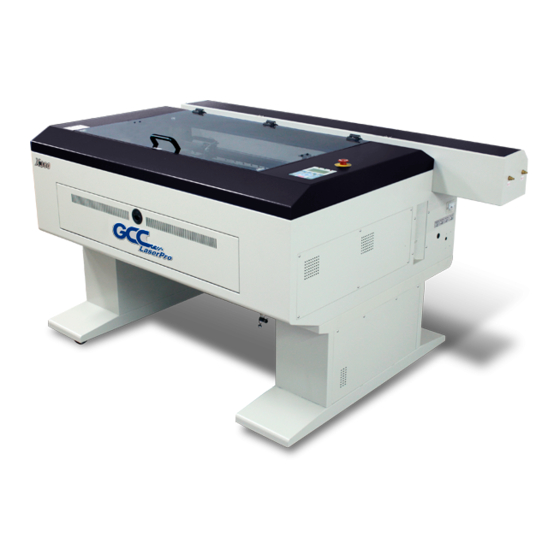
Chapter III - Mechanical Overview Please take some time to familiarize yourself with this section regarding the mechanical overview of the LaserPro X380. References will be made back to the different parts of the LaserPro X380 in later sections. 3.1 Front View SmartEXT™... -
Page 19: Top View
3.2 Top View Emergency Stop Button Control Panel 3.3 Right (Profile) View Power Water Inlet and ON/OFF Switch outlet... - Page 20 USB Port Error Indicators Power Cable Inlet Print Port...
-
Page 21: Left (Profile) View
3.4 Left (Profile) View 3.5 Rear View Laser Compartment Handles... -
Page 22: Chapter Iv - Setup And Installation
Laser Compartment Handles SmartEXT™ Pass-Through Door (Rear) Ventilation Opening Chapter IV - Setup and Installation 4.1 Machine Setup 4.1.1 Before Powering Up the Machine Connect the water hoses between the machine and the water chiller. Make sure the hoses are connected correctly with the right water flow directions. - Page 23 ●Always turn on the water chiller before turning on the machine. ●It is recommended to change the cooling water once every month. Remove water from the water chiller if machine will not be operated for an extended period of time. CAUTION Make sure to add water to the water chiller before turning on the machine.
- Page 24 NOTE Distilled water is recommended as the coolant. Propylene glycol can be used as an anti-freeze agent. The coolant used with the water chiller should have the following properties: Good heat conduction and low viscosity Anti dirt forming ...
-
Page 25: Powering Up The Machine
Ensure that the LaserPro X380 is connected to a 220V power source. 4.1.3 Connecting the Computer The LaserPro X380 can communicate with a computer through a USB Port or Parallel Printer Port connection interface. The USB Port connection offers faster file transfer rates and greater flexibility over the Parallel Printer Port connection. -
Page 26: Recommended Computer Configuration
Support will not be offered, if you experience output problems with non-supported graphics software. 4.2.1 Recommended Computer Configuration The LaserPro X380 operates under Windows operating systems and is designed to work on a computer that meets the following minimum requirements. Computer ... -
Page 27: Installation Of The Laserpro Print Driver
When working with the LaserPro X380 Print Driver within your graphics software, you will need to have the X380 set as the default printer to get proper output. If you select to not have the X380 be the default printer, please remember to manually change this on your own from within the graphic software printer selection area or from the Windows Control Panel ... -
Page 28: Parallels Desktops
4.2.6 Parallels Desktops MAC users can use GCC LaserPro machines by purchasing the Parallels Desktop software which alows you to install Windows OS in MAC computers and run Windows based software under MAC computer and output with GCC print driver. 1) Purchase Parallels Desktops on its official website. - Page 29 4) nter your Mac OS X User Name and Password then press “OK” 5) Press “Active” 6) Press “OK” when activation is complete.
- Page 30 7) Register Parallels Desktop 8) Press “Register” and “OK” to complete the installation of Parallels Desktop. 9) Open Parallels Desktop (in the Applications folder) then choose File →...
- Page 31 10) Press “Install Windows from DVD or image file” then press “continue” to install windows OS 11) Select CD-ROM drive with the Windows installation CD 12) Enter the Windows OS product key...
- Page 32 Select how you would like to run your Windows program. 14) After the prior setting is complete the windows OS installation procedure will start automatically. 15) Windows OS installation is complete then you can refer to “4.2.5 Installation of the LaserPro Print Driver” to install GCC LaserPro Print Driver. 16) Install the AP that you want to use after the above installation is complete.
-
Page 33: Using Inventor With Gcc Laserpro Machine
4.2.6 Using Inventor with GCC LaserPro machine 1. Start drawing. 2. Delete border and title block by right clicking on sheet1 and selecting delete. - Page 34 3. Set sheet size to match working area of engraver. Engraver working area can be found on the paper tab of the windows driver. 4. Start sketch.
- Page 35 5. Engraving a. Finish sketch. b. Right click on sketch and select properties. c. Line Type: By Layer d. Line Weight: By Layer e. Set color to match one of the 16 colors available in the pen tab of the windows driver. 6.
- Page 36 Note: All objects created in one particular sketch will have the same properties meaning all will engrave or all will cut. If you would like to engrave and cut in the same job you will need at least two sketches, one with all the engravings and another with all the cuts, to do so properly.
- Page 37 4.3 Water Chiller Set-up Instructions Water In / Water Out 1. The water chiller comes with two orange color water tubes 2. Connect the tubes to the machine. Connect the tube to the “Water Out” opening and the “Water In” opening.
-
Page 38: Chapter V - Operating The Laserpro X380
Once you have installed the LaserPro USB Driver (USB connectivity only), LaserPro Print Driver, and have connected the LaserPro X380 to your computer, you will need to familiarize yourself with the LaserPro X380’s control panel and LaserPro Print Driver. The print driver will... -
Page 39: Graphic Control Panel Overview (Description)
5.1.2 Graphic Control Panel Overview (Description) The Control Panel The control panel on the LaserPro X380 provides easy access to all of the manual controls needed for cutting. The liquid crystal display (LCD), functional, directional and selection buttons make navigating through the machine’s manual controls easy to do. - Page 40 POWER - The power light will illuminate when the LaserPro X380 is powered on. LASER - The laser light will illuminate when the laser is active and in operation.
-
Page 41: Graphic Control Panel Navigation Chart
5.1.3 Graphic Control Panel Navigation Chart Carriage / Work Table Main Work Page Adjustment Page Functions Page File Management Page Machine Information Page Machine Setting Page Link / DLink Page Set Lens Page File Information Page Tune Auto Focus Page Set Red Beam Page File Management Edit Page... -
Page 42: Graphic Control Panel Function Pages
LaserPro logo, and machine initialization pages before going to the main work page. Main Work Page The main work page is the page that the LaserPro X380 will default to upon startup and will be the “home base” for when navigating through the various functions of the control panel. This will be the page that is displayed when you are processing your jobs. - Page 43 Carriage / Work Table Adjustment Page ☼ navigating to this page: Main Work Page Press , , , , or F3 Carriage / Work Table Adjustment Page The Carriage / Work Table Adjustment Page allow you to manually increase and decrease the height of the work table (Z-axis).
- Page 44 File Management Page – this page allows you to manage the files that you have loaded onto the LaserPro X380. Machine Setting Page – this page allows you to access and modify a variety of your machine...
- Page 45 The File Management Page allows you to manage the files that you have loaded onto the LaserPro X380. You can scroll through your jobs, delete a selected job, delete all jobs, and go to the Link/DLink Page to set and arrange multiple loaded jobs into a single job queue for processing.
- Page 46 Link/DLink Page ☼ Navigating to this page: Main Work Page Press F4 Functions Page Select <File Management> from the menu File Management Page Press F2 Link / DLink Page The Link/DLink Page allows you to set, arrange, and remove loaded jobs to and from a job queue for processing.
- Page 47 File Information Page ☼ Navigating to this page: Main Work Page Press F4 Functions Page Select <File Management> from the menu File Management Page Select a job file and press Enter File Information Page The File Information Page allows you to view the speed, power, DPI, and PPI settings of the selected job.
- Page 48 File Management Edit Page ☼ Navigating to this page: Main Work Page Press F4 Functions Page Select <File Management> from the menu File Management Page Select a job file and press Enter File Information Page Press F4 File Management Edit Page The File Management Edit Page allows choosing to modify your raster or vector settings for the selected job, as well as setting the number of times to repeatedly process the selected job (Repeat Num).
- Page 49 PPI, and power ramp settings for the selected job. These settings correspond to the same settings found on the LaserPro X380 print driver. This page allows you to easily adjust these values to make immediate adjustments while processing your loaded jobs, even when you have disconnected your computer from the LaserPro X380.
- Page 50 Machine Setting Page ☼ Navigating to this page: Main Work Page Press F4 Functions Page Select <Machine Setting> from the menu Machine Setting Page The Machine Setting Page allows you to access and modify a variety of your machine settings, including: Set Lens, Tune Auto Focus, Set Table Down, Set Red Beam, Carriage Lock, Set Command Mode, Save Position, Flash Memory, Set File Save Mode, Set Vector Mode, Tune Image Power, Set Laser Wattage, Set Fine Mode, Other, Reset.
- Page 51 Remember to save your settings after you have made the proper changes. Now by pressing the Auto Focus button, the LaserPro X380 will auto focus properly using the new lens setting. The LaserPro X380’s default setting is <4.0”>...
- Page 52 Tune Auto Focus Page ☼ Navigating to this page: Main Work Page Press F4 Functions Page Select <Machine Setting> from the menu Machine Setting Page Select <Tune Auto Focus> from the menu Tune Auto Focus Page The Tune Auto Focus Page allows you to manually set the default auto focus distance / vertical height of the worktable (Z-axis) for when the Auto Focus button is pushed.
- Page 53 Pressing the Enter key at this point will confirm the prompt to move the work table to its lowest position. If the Table Down is set to <NO>, then the LaserPro X380 will not display this warning prompt at system startup.
- Page 54 ☼ Navigating to this page: Set Red Beam Page Main Work Page Press F4 Functions Page Select <Machine Setting> from the menu Machine Setting Page Select <Set Red Beam> from the menu Set Red Beam Page The Set Beam Page allows you to turn on or off the red dot laser pointer on the laser carriage. Enabling this function will indicate the exact location where the laser will fire upon.
- Page 55 ☼ Navigating to this page: Carriage Lock Page Main Work Page Press F4 Functions Page Select <Machine Setting> from the menu Machine Setting Page Select <Carriage Lock> from the menu Carriage Lock Page The Carriage Lock Page allows you to set whether the laser carriage is locked or free. If the Carriage Free setting is set to <YES>, then you will be able to manually move the laser carriage along the X and Y axis by hand with the top door open.
- Page 56 ☼ Navigating to this page: Set Command Mode Page Main Work Page Press F4 Functions Page Select <Machine Setting> from the menu Machine Setting Page Select <Set Command Mode > from the menu Set Command Mode Page The Set Command Mode Page allows you to configure vector settings when outputting in Default or HPGL mode.
- Page 57 ☼ Navigating to this page: Save Position Function Main Work Page Press F4 Functions Page Select <Machine Setting> from the menu Machine Setting Page Select <Save Position > from the menu The Save Position Function allows you to save the current X-axis and Y-axis positions of the laser carriage and sets this position to be the origin for subsequent jobs.
- Page 58 LaserPro X380 after the cutting process. Setting File Save to <YES> will retain all job files on the LaserPro X380, even after each job has been processed. File Save: YES / NO...
- Page 59 SmartGUARD Page Navigating to this page: Main Work Page press F4 Functions Page Select<Advanced Options>from the menu Machine Setting Page Select<SmartGUARD >from the menu SmartGUARD Page After hardware installation, please enter the function menu on the control panel to enable the SmartGUARD fire alarm.
- Page 60 Start / Stop Back to Main Work Page Auto Focus Initiate the auto focus function ▲ / ▼ Manual Focus Manually adjust the height of the work table (Z- Buttons axis) Reset Page SmartCut X380 User Manual - 46 -...
- Page 61 Reset Page The Reset Page allows you to reset all changes made to the LaserPro X380’s Machine Settings Page to their default settings. This does not affect the settings saved to an image file on the computer. The User Reset setting will set all settings back to the default. After any firmware updates, you must use the System Reset setting (your previous settings are saved).
- Page 62 Scroll through pages Start / Stop Back to Main Work Page Auto Focus Initiate the auto focus function ▲ / ▼ Manual Focus Manually adjust the height of the work table (Z- Buttons axis) Laserpro X380 User Manual - 51 -...
-
Page 63: The Laserpro X380 Print Driver
5.2.1 Page Setup and Orientation The first thing you must do before working with the LaserPro X380 Print Driver will be to make sure the page and layout settings are properly configured within your graphics software. You will need to access and edit the Page Setup or Layout page of your graphics software to set your graphics software’s page layout to match the LaserPro... -
Page 64: Color Management
Setup and Orientation properly set in your graphics software, you will also need to make sure Color Management is DISABLED prior to working with the LaserPro X380 Print Driver. If you do not properly From your graphic software’s Color Management page: ... -
Page 65: Using The Laserpro X380 Print Driver
LaserPro X380 Print Driver. The LaserPro X380 print driver allows you to adjust your cutting options. After you have setup your image, design, or text to be processed in your software application, you can access the LaserPro X380 print driver by going to FILE ... - Page 66 Note For this screenshot example, CorelDraw was used as the software application. The LaserPro X380 Print Driver consists of seven primary sections (pages) in which you will be able to choose various cutting options and settings: Option Page Pen Page ...
-
Page 67: Laserpro X380 Print Driver >> Option Page
Manual Color Fill: Select this mode when you would like to designate specific power and speed settings and link them to certain colors of your image. The LaserPro X380 print driver allows a maximum of 16 pen parameters to be set. - Page 68 History File: This section contains a list of the recent files you have recently created and worked with, please note that. SAVE: This function will save the current print driver parameter settings to a file and location on your computer of your selection.
-
Page 69: X380 Print Driver >> Pen Page
5.2.3.2 X380 Print Driver >> Pen Page The LaserPro X380 incorporates the use of 16 different colors to represent 16 different laser power and speed settings when cutting. These colors are referred to as “Pens”. Think of each pen as a designated laser setting, rather than as a color. - Page 70 NOTE The X380 print driver cannot store more than 16 pen colors or different laser parameter settings per file. Speed (Pen Page) [DEFAULT SETTING: 50] The speed slider controls the laser’s speed during operation (engraving speed) with settings ranging from 0.1 –...
- Page 71 PPI (Pen Page) [DEFAULT SETTING: 400] PPI (pulses-per-inch) represents the pulsing frequency of the laser pulse (fire) numbers within an inch exclusive for vector cutting. Higher PPI settings may cause more melting, burning or charring on the edges when cutting. Lower PPI settings may reduce this effect, but may result in a serrated looking edge.
-
Page 72: X380 Print Driver >> Advance Page
5.2.3.3 X380 Print Driver >> Advance Page Scaling (Advance Page) [DEFAULT SETTING: 0] In some cases you may find a slight output inaccuracy in the actual output compared to what you have set in the computer. This margin of error or offset is extremely small (approximately 1/300). What this means that there may be a 1-unit offset for every 300 unit increments. - Page 73 Position Mode set to Center, then the X380 will vector cut a circle around the initial position of the laser head. It is highly recommended you enable the red dot laser pointer when setting / adjusting the Position Modes, as this makes accurate positioning of your laser carriage for your particular jobs much easier.
-
Page 74: X380 Print Driver >> Paper Page
Paper Size (Paper Page) The paper size represents your total work area. Ensure that the paper size is never set greater than the X380’s worktable area of 36” x 24” (900mm x 600mm). The X value represents the length and the Y value represents the width. -
Page 75: X380 Print Driver >> Language Page
5.2.3.5 X380 Print Driver >> Language Page This page allows you specify the language displayed by the X380 Print Driver. Current language options allow for: English, Spanish, French, And Chinese (Simplified, Traditional), Japanese, and German. 64 232001250G(06) -
Page 76: Chapter Vi - Cutting Techniques
The LaserPro X380 Print Driver determines vector cut based on the outline width of that particular area or section of the design. In order to prep a particular section for vector cutting, you will need to set that object’s fill color to white and set its outline thickness between 0.001”... -
Page 77: Tips
6.2 3D Tips 3D Mode is one of the functions of LaserPro laser engraver. Instead of traditional two dimensional graphic processing, 3D Mode allows the naked eyes to visualize the curvatures of the 3D effect. Although it is easy to produce 3D samples with LaserPro Engraver, production of the 3D graphic can be a hassle for our users. - Page 78 As illustrated in the figure below, all you need to do is to choose the direction of the vector and then set the length and shape of the convex or concave surface. The software will automatically generate the 3D graphic for you. Illustration for the production of 3D graphics with Laser Professional AP In addition, you may output the completed graphic directly to the Laser Engraver, which is very handy.
- Page 79 Step 1. Produce the gray level background 68 232001250G(06)
- Page 80 LaserPro requests your attention If you need to produce circular 3D graphics, you only need to select Radial as the gray level type in the pull-down menu of Type. Then, a circular 3D graphic may be produced. Step 2. Produce three-dimensional characters 69 232001250G(06)
- Page 81 70 232001250G(06)
- Page 82 Step 3. Edit the characters for the website Step 4. Combine the 3D images After finishing the production for each of the objects, you may proceed with the combination of the objects. The combined graphic may be output with the laser engraver. Output the 3D graphic After selecting the graphic to be output, set the Mode as 3D Mode in the driver.
- Page 83 Tips for engraving 3D graphics LaserPro Application Lab provides a few reminders that may require your attention during the 3D engraving in order to improve the result of the engraving. Turn on the Air Assist function When the engraving is done along with Air Assist, the depth of the engraving would be deeper. Set Air assist inside the driver by checking the box.
-
Page 84: Chapter Vii - Optional Items
2) Mount the exhaust system in an obvious and accessible location, not too far from the X380, so it can be routinely switched on prior to laser engraving. The maximal distance you should mount the exhaust system away from the X380 depends on the blower’s vacuum capacity. -
Page 85: Air Compressor Option
It is important that the ¼” air tubing has clean, straight cuts on each end. Jagged or slanted cuts will not produce adequate sealing capabilities. 4) Locate the air tube valve positioned towards the front side of X380. As indicated below: 74 232001250G(06) - Page 86 LaserPro X380 print driver and hardware control panel. Please refer to the LaserPro X380 print driver and graphic control panel sections of this manual for details on how to enable and configure air-assist functionalities.
-
Page 87: Smartbox Option
7.3 SmartBOX Option The SmartBOX is an innovative combination of a cutting box, honeycomb table, and material support stands. During the cutting and engraving process, unwanted scrap, dust, and vapor byproducts are left behind. The cutting box collects the larger scrap byproducts while venting out the smaller dust particles, vapors, and smoke to minimize excess buildup on the machine, worktable, and your project. - Page 88 4) Insert the cutting box through the open front pass-through door onto the worktable, with the air extraction opening facing towards the back end of the LaserPro X380. Ensure the rear and left side of the cutting box is aligned flush to the edges of the left and right rulers on the worktable.
-
Page 89: Smartair Fine / Ultra Nozzles Option
LaserPro X380 print driver and hardware control panel. Please refer to the LaserPro X380 print driver and graphic control panel sections of this manual for details on how to enable and configure air-assist functionalities. - Page 90 Sensitivity: The sensitivity of the SmartGUARD is adjustable. The user can select the delay time from 1 second to 9 seconds when a fire is detected until alarm activation and automatic system shutdown. As an example, if the firmware is set to 1 second, then the SmartGUARD fire alarm will alert and automatically shutdown the laser system 1 second after detecting a fire.
-
Page 91: Rotary Attachment Option
7.4 Rotary Attachment Option The rotary attachment option provides the Spirit with the ability to engrave on cylindrical or spherical objects. In addition to the standard X, Y, Z axis, the rotary attachment allows for a fourth axis which rotates your object 360° to allow for engraving on cups, wine glasses, and even balls. Work Piece Limitations Maximum Length 450 mm (17.71 inches) - Page 92 Rotary Attachment Port Close the front panel. 6) The rotary attachment is now properly installed. Power on the Spirit and the rotary attachment will be automatically detected and the engraving table will automatically move to its lowest position. 7) Despite the dummy-proof installation design, please ensure that the device is installed correctly before turning on the machine OPERATION: 1) Use a ruler to measure the diameter (at the point on the work piece you will be engraving) and...
-
Page 93: Chapter Viii Basic Maintenance
Electrical Shock may occur if you do not turn off and unplug the X380 before cleaning. Damage may occur to the system if you do not turn off and unplug the X380 before cleaning. Always turn off and unplug the X380 before cleaning! -
Page 94: Suggested Cleaning And Maintenance Supplies
4) Apply a soap solution, all-purpose cleaner, or alcohol to a paper or cotton towel to wipe down the rails of the motion system. 5) Wait for all cleaning residue to dry completely before plugging in and operating the X380. CAUTION ... -
Page 95: Cleaning The Optics System
This mirror is located inside the laser cabinet of the LaserPro X380. 1) Use a #2 Phillips Screwdriver to open the rear laser cabinet of the LaserPro X380. 2) Loosen the thumbscrew and remove the dust cover securing the mirror. (As shown in the picture below). - Page 96 6) Replace and secure the outer access panel. Mirror 2, 3, 4 These mirrors are located in the worktable area of the LaserPro X380. Mirror 2 Mirror 3 Mirror 4 Mirror 2 1) Unscrew and remove the black dust cover covering mirror 2.
-
Page 97: Cleaning The Mirrors
Focus lens Reflection mirror 3) Clean the lens in the proper manner. 4) Re-install mirror 4 after cleaning. 5) Tighten the top thumbscrew. 6) Reinstall the laser carriage panel and tighten the three thumbscrews. 8.2.2 Cleaning the Mirrors After you have removed each mirror, you will want to inspect each mirror for scratches, smoke residue, or debris. -
Page 98: Removing And Cleaning The Focal Lens
CAUTION If the center of the mirror is scratched, contact your LaserPro X380 dealer for a replacement. 8.2.3 Removing and Cleaning the Focal Lens 1) Unscrew the three thumbscrews (front face of the laser head) securing the laser carriage panel and remove the laser carriage panel to reveal the focal lens. - Page 99 software driver or the control panel. 3. Please check if the laser power connector is loose. 4. For safety purpose, the laser beam will not be generated when the top or front door is opened unless you short the connector of the magnetic switches. 5.
-
Page 100: Glossary
Chapter X – Appendix 10.1 Glossary Color Fill – Term within the awards and engraving industry used to describe the variety of techniques used to add color or contrast to engraving. DPI – Dots Per Inch or Pixels Per Inch. The resolution of an image as defined by the amount of dots/pixels included in an inch. -
Page 101: Laserpro X380 Specification Sheet
10.2 LaserPro X380 Specification Sheet X380 Models X380RX Wattage 100W Laser source Sealed CO2 Laser Cooling Water Cool Working Area 38 x 24 in. (960 x 610 mm) All doors closed 41 x 25 x 6.5 in. (1041 x 635 x 165 mm) Max.
Need help?
Do you have a question about the X380 and is the answer not in the manual?
Questions and answers