Table of Contents
Advertisement
Quick Links
Advertisement
Table of Contents

Related Manuals for Belden HIRSCHMANN SPIDER II 16TX EEC


Summary of Contents for Belden HIRSCHMANN SPIDER II 16TX EEC
- Page 1 User Manual Installation Industrial Ethernet Rail Switch SPIDER II 16TX EEC, SPIDER II 16TX/2DS-S EEC SPIDER II 16TX EEC SPIDER II 16TX/2DS-S EEC Installation SPIDER II 16TX Technical Support Release 02 12/2014 https://hirschmann-support.belden.eu.com...
- Page 2 The naming of copyrighted trademarks in this manual, even when not specially indicated, should not be taken to mean that these names may be considered as free in the sense of the trademark and tradename protection law and hence that they may be freely used by anyone. ©...
-
Page 3: Table Of Contents
Contents Safety instructions About this Manual Legend Description General device description Description of the device variants Ethernet ports 1.3.1 10/100 Mbit/s twisted pair port 1.3.2 100/1000 Mbit/s F/O port (optional) Display elements Installation Checking the package contents Installing and grounding the device 2.2.1 Installing the device onto the DIN rail 2.2.2 Grounding the device Wiring the terminal block for the supply voltage and the... - Page 4 Installation SPIDER II 16TX Release 02 12/2014...
-
Page 5: Safety Instructions
Safety instructions General safety instructions You operate this device with electricity. Improper usage of the device entails the risk of physical injury or significant property damage. The proper and safe operation of this device depends on proper handling during transportation, proper storage and installation, and careful opera- tion and maintenance procedures. - Page 6 Supply voltage The supply voltage is electrically isolated from the housing. Ground the device before connecting any other cables. Connect only a supply voltage that corresponds to the type plate of your device. Every time you connect the electrical conductors, make sure that the following requirements are met: ...
- Page 7 Housing Only technicians authorized by the manufacturer are permitted to open the housing. Never insert pointed objects (narrow screwdrivers, wires, etc.) into the device or into the connection terminals for electric conductors. Do not touch the connection terminals. ...
- Page 8 The device can be used in the industrial sector. Interference immunity: EN 61000-6-2 Emitted interference: EN 55022 Warning! This is a class A device. This device can cause interference in living areas, and in this case the operator may be required to take appro- priate measures.
- Page 9 Subject devices are to be installed in an ATEX Certified IP54 (as defined in EN 60079-0 and EN 60079-15) enclosure and accessible only by the use of a tool. Subject devices are for use in an area of not more than pollution degree 2 in accordance with IEC 60664-1.
-
Page 10: About This Manual
About this Manual The “Installation User Manual” document contains a device description, safety instructions, a display description and other information that you require to install the device before starting with the configuration of the device. Legend The symbols used in this manual have the following meanings: ... -
Page 11: Description
Description General device description The SPIDER II 16TX devices are designed for the special requirements of industrial automation. They meet the relevant industry standards, provide very high operational reliability, even under extreme conditions, and also long-term reliability and flexibility. The devices allow you to set up switched industrial Ethernet networks that conform to the IEEE 802.3 standard. -
Page 12: Ethernet Ports
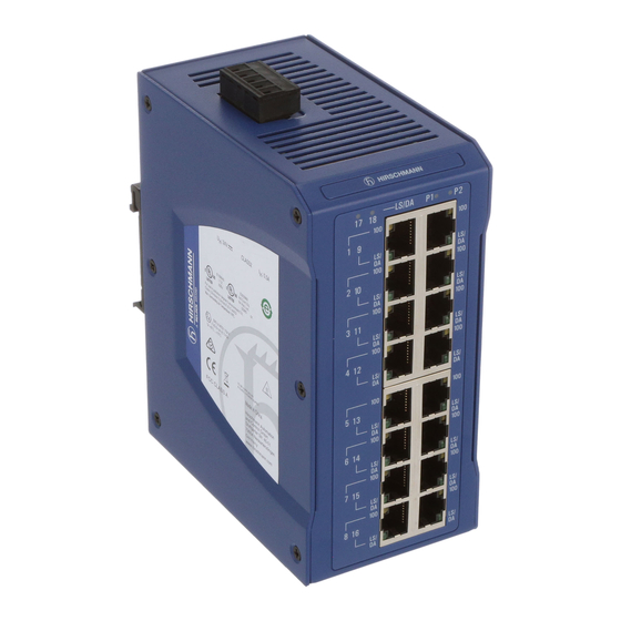
SPIDER II 16TX EEC SPIDER II 16TX/2DS-S EEC 5 pin, pluggable terminal block for redundant power supply LED display elements RJ45 socket for 10/100 Mbit/s twisted pair connections SFP slot for 100/1000 Mbit/s F/O connection Table 2: Overview: interfaces, display elements, and terminal block for the supply voltage Ethernet ports 1.3.1... -
Page 13: 100/1000 Mbit/S F/O Port (Optional)
Display Color Activity Meaning Data rate Yellow Lights up 100 Mbit/s connection None 10 Mbit/s connection LS/DA Link status Green Lights up Device detects a valid link data Flashing Device is transmitting and/or receiving data None Device detects an invalid or missing link 1.3.2 100/1000 Mbit/s F/O port (optional) -
Page 14: Display Elements
Display elements LS/DA Figure 1: 1 – Relevant for SPIDER II 16TX/2DS-S EEC: Information on F/O port status 2 – All devices: Information on supply voltage Activity Meaning Lights up Device detects a valid link Flashing Device is transmitting and/or receiving data None Device detects an invalid or missing link Lights up... -
Page 15: Installation
Installation The devices have been developed for practical application in a harsh indus- trial environment. On delivery, the device is ready for operation. To configure a subdomain, follow these steps: Checking the package contents Installing and grounding the device ... -
Page 16: Grounding The Device
To mount the device onto a horizontally mounted 35 mm DIN rail according to DIN EN 60715, proceed as follows: Slide the upper snap-in guide of the device into the DIN rail. Press the media module downwards onto the clip-in bar. ... -
Page 17: Wiring The Terminal Block For The Supply Voltage And The Grounding
Wiring the terminal block for the supply voltage and the grounding WARNING ELECTRIC SHOCK Never insert pointed objects (narrow screwdrivers, wires, etc.) into the device or into the connection terminals for electric conductors. Do not touch the connection terminals. Start connecting the electrical wires only if all the above safety require- ments are fulfilled. -
Page 18: Operating The Device
Operating the device CAUTION ELECTRIC SHOCK Connect only a supply voltage that corresponds to the type plate of your device. Failure to follow these instructions can result in injury or equipment damage. By connecting the supply voltage via the terminal block, you start the opera- tion of the device. -
Page 19: Installing An Sfp Transceiver (Optional)
Installing an SFP transceiver (optional) Remove the protective cap from the SFP transceiver. Push the SFP transceiver with the lock closed into the socket until you hear it latch in. Note: For this device, only use suitable SFP modules from Hirschmann. See “Accessories”... -
Page 20: Maintenance And Service
Maintenance and service When designing this device, Hirschmann largely avoided using high-wear parts. The parts subject to wear and tear are dimensioned to last longer than the lifetime of the product when it is operated normally. Operate this device according to the specifications. ... -
Page 21: Disassembly
Disassembly Disconnect the data cables. Disable the supply voltage. Remove the power connector from the device. Removing the device from the DIN rail To remove the device from the DIN rail, press the device downwards and pull it out from under the DIN rail. -
Page 22: Technical Data
Technical data General technical data Dimensions See “Dimension drawings” on page 23. W × H × D Weight 25.75 oz (730 g) Power supply 2 voltage inputs for redundant power supply Safety extra-low voltage (SELV), redundant inputs disconnected ... - Page 23 Dimension drawings inch 4.72 4.37 EMC and immunity EMC interference emis- sion Radiated emission FCC 47 CFR Part 15 Class A EN 55022 Fulfilled Conducted emission FCC 47 CFR Part 15 Class A EN 55022 Fulfilled EMC interference immu- nity Electrostatic discharge EN 61000-4-2...
- Page 24 EMC interference immu- nity EN 61000-4-5 line/ground 1 kV EN 61000-4-5 line/line 0.5 kV Voltage surges - data line EN 61000-4-5 line/ground 1 kV Conducted disturbances EN 61000-4-6 150 kHz ... 80 MHz 10 V Stability IEC 60068-2-6, test Fc Vibration 3 Hz ...
- Page 25 Product Wave Fiber System Example Fiber code length attenua- for F/O line attenua- dispersion M-SFP-... tion length tion -MX/LC MM 1310 nm 50/125 µm 0-12 dB 0-1.5 km 1.0 dB/km 800 MHz×km -MX/LC MM 1310 nm 62.5/125 µm 0-12 dB 0-500 m 1.0 dB/km 500 MHz×km -LX/LC...
- Page 26 Scope of delivery Number Article Device 5 pin, pluggable terminal block for redundant power supply Installation user manual Order numbers Device Order number Rail Switch SPIDER II 16TX EEC 942 120-001 Rail Switch SPIDER II 16TX/2DS-S EEC 942 121-001 Accessories ...
- Page 27 Other accessories Order number Rail Power Supply RPS 80 EEC 943 662-080 Rail Power Supply RPS 120 EEC (CC) 943 662-121 Underlying technical standards Name UL 508 Safety for Industrial Control Equipment CSA C22.2 No. 142 Canadian National Standard(s) – Process Control Equipment – Industrial Products EN 55022 Information technology equipment –...
- Page 28 Installation SPIDER II 16TX Release 02 12/2014...
-
Page 29: A Further Support
Contact our support at https://hirschmann-support.belden.eu.com You can contact us in the EMEA region at Tel.: +49 (0)1805 14-1538 E-mail: hac.support@belden.com in the America region at Tel.: +1 (717) 217-2270 E-mail: inet-support.us@belden.com in the Asia-Pacific region at ...
Need help?
Do you have a question about the HIRSCHMANN SPIDER II 16TX EEC and is the answer not in the manual?
Questions and answers