
Subscribe to Our Youtube Channel
Related Manuals for Belden lumberg automation 0960 IOL 3816-001


Summary of Contents for Belden lumberg automation 0960 IOL 3816-001
- Page 1 Manual LioN-X IO-Link Hub 0960 IOL 3816-001 (16DIO low current Hub) Manual LioN-X IO-Link Hub Technical Support Version 1.0 11/2023 lumberg-automation-support.belden.com...
-
Page 2: Table Of Contents
Contents Contents 1 About this manual 1.1 General information 1.2 Explanation of symbols 1.2.1 Use of danger information 1.2.2 Use of general information 1.3 Version information 2 Safety instructions 2.1 Intended use 2.2 Qualified personnel 3 Designations and synonyms 4 System description 4.1 About LioN-X 4.2 IO-Link basics 4.3 Device variants... - Page 3 Contents 5.3.2 Ports for sensors/actuators 6 Configuration and startup 7 Process data assignment 7.1 16DIO: 0960 IOL 3816-001 7.1.1 Input Data 7.1.2 Output Data 8 Parameterization of the IO-Link Hub 8.1 IO-Link data storage 8.2 IO-Link block parameterization 8.3 IO-Link factory reset 8.4 16DIO: 0960 IOL 3816-001 8.5 Description of parameter data 8.5.1 Parameter –...
- Page 4 Contents 10 IO-Link IODD 10.1 Device description file download 11 Technical data 11.1 General 11.2 IO-Link interface 11.3 Power supply for the module electronics/sensors 11.4 Digital inputs 11.4.1 Variant 0960 IOL 3816-001 11.5 Digital outputs 11.5.1 Variant 0960 IOL 3816-001 11.6 LEDs 12 Accessories Manual LioN-X IO-Link Hub...
-
Page 5: About This Manual
Im Gewerbepark 2 D-58579 Schalksmühle Germany lumberg-automation-support.belden.com www.lumberg-automation.com catalog.belden.com Belden Deutschland GmbH – Lumberg Automation™ – reserves the right to make technical changes or changes to this document at any time without notice. Manual LioN-X IO-Link Hub Version 1.0 11/2023... -
Page 6: Explanation Of Symbols
Table 1: Overview of manual revisions Attention: In the interest of product improvement and further development, BELDEN reserves the right to change technical data in this manual or changes to the product without prior notice. Manual LioN-X IO-Link Hub Version 1.0 11/2023... -
Page 7: Safety Instructions
2 Safety instructions 2.1 Intended use 2 Safety instructions 2.1 Intended use The products described in this manual are decentralized Input/Output assemblies on a fieldbus I/O network. We adhere to all safety standards when developing, producing, testing, and documenting our products. When you adhere to the handling specifications and safety instructions described for the configuration, assembly, and correct operation, there should not normally be any risks for people or equipment. -
Page 8: Qualified Personnel
Only Belden Deutschland GmbH – Lumberg Automation™ – is permitted to make changes to the hardware or software of the products that go beyond the scope of this manual. -
Page 9: Designations And Synonyms
3 Designations and synonyms 3 Designations and synonyms Add-On Instruction Application Programming Interface Bus Fault LED Big Endian Data format with High-B on first place (PROFINET and IO-Link) Back-Up Inconsistency (EIP diagnostics) CC-Link IE Field I/O port pin 4 mode, IO-Link communication/switching signal Ch. - Page 10 3 Designations and synonyms Enterprise Resource Planning system ETHERNET Functional Earth Force Mode Enabled (EIP diagnostics) Functional Safety Fast Start-Up GSDML General Station Description Markup Language High-B High-Byte HTTPS Hyper Text Transfer Protocol Secure IO-Link port COM Error (EIP diagnostics) Invalid Cycle Time (EIP diagnostics) IO-Link port Device Error (EIP diagnostics) IO-Link port Device Notification (EIP diagnostics)
- Page 11 3 Designations and synonyms Little Endian Data format with Low-B on first place (EtherNet/IP) LLDP Link Layer Discovery Protocol Low-B Low-Byte Least Significant Bit Low Voltage Actuator Supply (EIP diagnostics) Low Voltage System/Sensor Supply (EIP diagnostics) Management Information Base Multiprotocol: PROFINET + EtherNet/IP + EtherCAT ®...
- Page 12 3 Designations and synonyms Short Circuit Actuator/U (EIP diagnostics) Short Circuit Sensor (EIP diagnostics) SFRT Safety Function Response Time SIO mode Standard Input Output mode SLMP Seamless Message Protocol SNMP Simple Network Management Protocol Single Protocol (PROFINET, EtherNet/IP, EtherCAT ® Modbus TCP or CC-Link IE Field Basic) Startup Parameterization Error (EIP diagnostics) Test Channel B...
-
Page 13: System Description
Use all benefits of the Lumberg Automation product solution by additionally ™ downloading the configuration tool LioN-Management Suite V2.0 from www.belden.com to enable e.g. a fast and easy parameterization of the connected IO-Link devices via the embedded IODD interpreter. Manual LioN-X IO-Link Hub... -
Page 14: Io-Link Basics
4.2 IO-Link basics 4 System description 4.2 IO-Link basics IO-Link is a globally standardized technology that enables communication between devices ranging from complex and intelligent sensors through to the central control unit. The IO-Link standard is specified according to the standard IEC 61131-9 and represents the basis of communication. - Page 15 4 System description 4.3 Device variants Article Product designation Description I/O port functionality number 935712001 0960 IOL 3816-001 LioN-X M12 60 mm, 8 x IO-Link Class A 16DIO low current IO- Link Hub Table 3: Overview of LioN-X Hub variants IO-Link Hub –...
-
Page 16: Assembly And Wiring
5.1 General information 5 Assembly and wiring 5 Assembly and wiring 5.1 General information Mount the device on a flat surface using 2 screws (M4x25/30). The torque required is 1 Nm. Use washers compliant with DIN 125 for all types of mounting, maintaining a distance of 149.3 mm (5.878 in) to 150.8 mm (5.937 in) between the mounting holes. - Page 17 5 Assembly and wiring 5.1 General information Attention: For UL application: The installation and operation of the devices is only permitted for interior use. Please observe the maximum installation and operating height of 2000 m (6561 ft) above sea level. Approved up to a maximum pollution degree of 2.
-
Page 18: Outer Dimensions
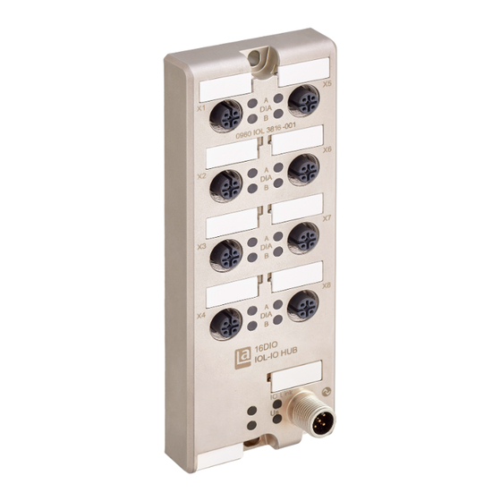
5.2 Outer dimensions 5 Assembly and wiring 5.2 Outer dimensions 5.2.1 16DIO variant Figure 1: 0960 IOL 3816-001 Manual LioN-X IO-Link Hub Version 1.0 11/2023... -
Page 19: Port Assignments
5 Assembly and wiring 5.3 Port assignments 5.3 Port assignments All the contact arrangements shown in this chapter show the frontal view of the connection area for the connectors. 5.3.1 IO-Link interface Design: M12 connector, 5-pin, A-coded Color coding: black Figure 2: Schematic diagram port X01 16DIO (Class A) Function... -
Page 20: Ports For Sensors/Actuators
5.3 Port assignments 5 Assembly and wiring 5.3.2 Ports for sensors/actuators Design: M12 socket, 5-pin, A-coded Color coding: black Figure 3: Schematic diagram ports X1 to X8 16DIO Function 0960 IOL 3816-001 Ports X1-X8 +24 V DC Sensor supply IN / OUT B Dig. -
Page 21: Configuration And Startup
6 Configuration and startup 6 Configuration and startup The BELDEN IO-Link Hub variants are operated with an IO-Link Master from version 1.1 (the BELDEN IO-Link Masters support only the standard 1.1 version). The data storage mechanism is only supported in conjunction with an IO-Link Master with the standard 1.1 version. -
Page 22: Process Data Assignment
This chapter describes the assignment of the process data of the controller to the I/O channels. The process data length is invariable for all Belden IO-Link Hubs. The following tables show the structure of the data. It is not possible to configure the process data length. -
Page 23: 16Dio: 0960 Iol 3816-001
7.1 16DIO: 0960 IOL 3816-001 7.1.1 Input Data This device supplies a total of four bytes of input data, the input process image is mapped in the first two bytes as follows: Standard Belden Mapping, (LioN-X mapping) Bit 7 Bit 6 Bit 5... -
Page 24: Output Data
7 Process data assignment 7.1.2 Output Data This device also supplies four bytes of output data, the output process image is mapped in the first two bytes as follows: Standard Belden Mapping, (LioN-X mapping) Bit 7 Bit 6 Bit 5... -
Page 25: Parameterization Of The Io-Link Hub
IO-Link Master port. 8.1 IO-Link data storage The BELDEN IO-Link Hub and the BELDEN IO-Link Masters support the data storage functionality. All user-configurable parameters are stored on the hub and on the master (Exceptions: user serial number, index 0x48 and tool identification, index 0x60). -
Page 26: 16Dio: 0960 Iol 3816-001
8.4 16DIO: 0960 IOL 3816-001 Index Sub- Parameter Access Data Data type Default value Index length [byte] 0x0010 Vendor name String BELDEN Deutschland GmbH 0x0011 Vendor text String www.beldensolutions.com 0x0012 Product name String 0960 IOL 3816-001 0x0013 Product ID String... -
Page 27: Description Of Parameter Data
8 Parameterization of the IO-Link Hub 8.5 Description of parameter data Index Sub- Parameter Access Data Data type Default value Index length [byte] 0x0048 1-16 User serial number String 0x0060 Tool identification 0 (b7: res. + b6 ... b0) Table 11: Device parameters (individual) 8.5 Description of parameter data 8.5.1 Parameter –... -
Page 28: Parameter - Input Filter
8.5 Description of parameter data 8 Parameterization of the IO-Link Hub Index Subindex/ Parameter Data number length 1 bytes 0x40 I/O data mapping, 0 = LioN-X (A/B, A/B, …, channel order), 1 = LioN-Classic (A, A, A … channel / B, B, B, … channel order) 0x40 DIS-AE-AR: Disable actuator error auto restart, 0 = false, 1 = true (only devices with DO function, otherwise do not use) -
Page 29: Parameter - Input Signal Extension
8 Parameterization of the IO-Link Hub 8.5 Description of parameter data Index Subindex/ Parameter value Data number channel / length port 16 bytes 0x43 9 / X5B 0 = Off, 1-255 = Input filter in ms 0x43 10 / X6A 0 = Off, 1-255 = Input filter in ms 0x43 11 / X6B... -
Page 30: Parameter - Input Logic Settings (No/Nc)
8.5 Description of parameter data 8 Parameterization of the IO-Link Hub Index Subindex/ Parameter Data number channel / length port 16 bytes 0x44 11 / X6B 0 = Off, 1-255 = Input signal extension in ms 0x44 12 / X7A 0 = Off, 1-255 = Input signal extension in ms 0x44 13 / X7B... -
Page 31: Parameter - Fail-Safe Settings
8 Parameterization of the IO-Link Hub 8.5 Description of parameter data 8.5.5 Parameter – fail-safe settings Attention: Only devices with DO function, otherwise do not use. The parameters setting determines the behavior of the digital outputs in the event of a communication loss. Each channel can be configured individually. Index Subindex/ Parameter... - Page 32 8.5 Description of parameter data 8 Parameterization of the IO-Link Hub A Surveillance Timeout can be set with this parameter configuration, which determines the monitoring procedure of the possible output overload for each digital channel. The delay time starts after a change to the output channel status.
-
Page 33: Parameter - User Serial Number
8 Parameterization of the IO-Link Hub 8.5 Description of parameter data 8.5.7 Parameter – User serial number This parameter allows the user to set a user-specific serial number. The user- specific serial number is output when the identification parameter, index 0x15, is read. -
Page 34: Diagnostic Properties
9.1 Device Status 9 Diagnostic Properties 9 Diagnostic Properties The devices offer the following diagnostic messages dependent on their function: 9.1 Device Status Index Length Parameter Index / Data length 1 Byte 0x24 Octet Value Definition Device is operating properly. Maintenance-Required Out-of-Specification Functional-Check Failure... -
Page 35: Device Status In Detail
9 Diagnostic Properties 9.2 Device status in detail 9.2 Device status in detail Index Subindex / Length Parameter data length N x ArrayT 0x25 1-24 Subindex Object name Data type Comment Error_Warning_1 3 octets All octets 0x00: no error/warning Octet 1: Event qualifier Error_Warning_2 3 octets Octet 2, 3: Event code... - Page 36 9.2 Device status in detail 9 Diagnostic Properties Bits Description b7 ... b6 Mode Value Definition Reserved Event single shot Event disappears Event appears b5 ... b4 Type Value Definition Reserved Notification Warning Error Source Value Definition Device (remote) Master (local) b2 ...
- Page 37 9 Diagnostic Properties 9.2 Device status in detail Event Type Device Description code Status 0x5111 Warning 2 Low voltage sensor (U 0x7710 Error Sensor error (short circuit) 0x8CB0 Error Actuator error X1A 0x8CB1 Error Actuator error X1B 0x8CB2 Error Actuator error X2A 0x8CB3 Error Actuator error X2B...
- Page 38 10.1 Device description file download You can find the matching device description file in each case in the BELDEN download area at: http://www.beldensolutions.com/en/Service/download_center or in the IO-Link Community download area at https://ioddfinder.io-link.com.
-
Page 39: Manual Lion-X Io-Link Hub
The following sections give an overview of the most important functional data needed to operate the device. For further information and detailed technical data, see the respective Data Sheet of your required product in the product specific download area on catalog.belden.com. Manual LioN-X IO-Link Hub Version 1.0 11/2023... -
Page 40: General
11.1 General 11 Technical data 11.1 General Ambient temperature during operation -20° C … +70° C (-4° F … +158° F) Ambient temperature during operation – EEC variant -40° C … +70° C (-40° F … +158° F) Ambient storage temperature -40° C … +85° C (-40° F … +185° F) Ambient humidity 98% RH (for UL applications 80% PRH) Weight... -
Page 41: Io-Link Interface
11 Technical data 11.2 IO-Link interface 11.2 IO-Link interface Specification IO-Link spec. v1.1.3 Physical transmission IO-Link, 24 V Half duplex Transfer rate COM 3 (230.4 kBaud) Com3 Limitation max. 20 m (65.6 ft) IO-Link expansion IO-Link standard IEC 61131-9 Process data 4 bytes input data 4 bytes output data Frame type Type_2_V... - Page 42 11.3 Power supply for the module 11 Technical data electronics/sensors Operational indicator (U LED green, 18 V <= U <= 30 V LED red, U < 18 V Table 20: Information on the power supply for the module electronics/ sensors )The modules should be supplied with a Limited Energy power supply in accordance with UL 61010-1, 3rd edition, section 9.4, or with LPS (Limited Power Source) in accordance with UL 60950-1 or class 2 in accordance with UL 1310 or UL 1585.
-
Page 43: Digital Inputs
11 Technical data 11.4 Digital inputs 11.4 Digital inputs 11.4.1 Variant 0960 IOL 3816-001 Standard digital input (8/16DIO) Type 1 In accordance with IEC 61131-2 Input current at 24 V DC Typically 5.3 mA Input channels 16 x Input type Normally open p-switching Input filter Configurable via software... -
Page 44: Leds
11.6 LEDs 11 Technical data Fail safe condition Configurable via software Low (default), high, hold last Status indicator Yellow LED for channel A White LED for channel B Diagnostic indicator Respective channel LED flashing Table 22: Release notes on the outputs 11.6 LEDs LED color Description... -
Page 45: Accessories
12 Accessories 12 Accessories In order to get access to various types of accessories, please visit our Web page: http://www.beldensolutions.com Manual LioN-X IO-Link Hub Version 1.0 11/2023...
Need help?
Do you have a question about the lumberg automation 0960 IOL 3816-001 and is the answer not in the manual?
Questions and answers