
Related Manuals for Belden Hirschmann SPIDER-SL-20-08T1999999SY9HHHH


Summary of Contents for Belden Hirschmann SPIDER-SL-20-08T1999999SY9HHHH
- Page 1 User Manual Installation Industrial Ethernet Rail Switch SPIDER Standard Line Installation SPIDER-SL Technical support Release 07 05/2022 https://hirschmann-support.belden.com...
- Page 2 The naming of copyrighted trademarks in this manual, even when not specially indicated, should not be taken to mean that these names may be considered as free in the sense of the trademark and tradename protection law and hence that they may be freely used by anyone. ©...
-
Page 3: Table Of Contents
Contents Important information Safety instructions About this Manual Description General device description Device name and product code Device view 1.3.1 Front view Power supply 1.4.1 Supply voltage with the characteristic value HH 1.4.2 Supply voltage with characteristic value HK Ethernet ports 1.5.1 10/100/1000 Mbit/s twisted pair port 1.5.2 10/100 Mbit/s twisted pair port 1.5.3 100/1000 Mbit/s F/O port... - Page 4 2.4.2 Connecting the 3-pin voltage terminal with spring (device variants with the characteristic value HK) Operating the device Connecting data cables Monitoring the ambient air temperature Maintenance and service Disassembly Removing an SFP transceiver (optional) Removing the device Technical data Further support Installation SPIDER-SL Release 07 05/2022...
-
Page 5: Important Information
Important information Note: Read these instructions carefully, and familiarize yourself with the device before trying to install, operate, or maintain it. The following notes may appear throughout this documentation or on the device. These notes warn of potential hazards or call attention to information that clarifies or simplifies a procedure. - Page 6 NOTICE NOTICE provides information about procedures that do not involve the risk of injury. Installation SPIDER-SL Release 07 05/2022...
-
Page 7: Safety Instructions
Safety instructions General safety instructions You operate this device with electricity. Improper usage of the device entails the risk of physical injury or significant property damage. The proper and safe operation of this device depends on proper handling during transportation, proper storage and installation, and careful operation and maintenance procedures. - Page 8 Strain relief Note: If the strain relief is insufficient, there is a potential risk of torsion, contact problems and creeping interruptions. Relieve the connection points of cables and lines from mechanical stress. Design strain reliefs in such a way that they help prevent any mechanical damage to cables, wires or conductors caused by external influences or their own weight.
- Page 9 Shielding ground The shielding ground of the connectable twisted pair cables is connected to the ground connection as a conductor. Beware of possible short circuits when connecting a cable section with conductive shielding braiding. Requirements for connecting electrical wires ...
- Page 10 CE marking The labeled devices comply with the regulations contained in the following European directive(s): 2011/65/EU and 2015/863/EU (RoHS) Directive of the European Parliament and of the Council on the restriction of the use of certain hazardous substances in electrical and electronic equipment.
- Page 11 Electromagnetic Compatibility Regulations 2016 The UKCA conformity declaration will be available to the relevant authorities at the following address: Belden UK Ltd. 1 The Technology Centre, Station Road Framlingham, IP13 9EZ, United Kingdom You find the UKCA conformity declaration as PDF file for downloading on the Internet at: https://www.doc.hirschmann.com/certificates.html...
- Page 12 Supplier's Declaration of Conformity 47 CFR § 2.1077 Compliance Information SPIDER-SL U.S. Contact Information Belden – St. Louis 1 N. Brentwood Blvd. 15th Floor St. Louis, Missouri 63105, United States Phone: 314.854.8000 This device complies with part 15 of the FCC Rules. Operation is subject...
-
Page 13: About This Manual
About this Manual The “Installation” user manual contains a device description, safety instructions, a description of the display, and the other information that you need to install the device. Documentation mentioned in the “User Manual Installation” that is not supplied with your device as a printout can be found as PDF files for downloading on the Internet at: https://www.doc.hirschmann.com Installation SPIDER-SL... -
Page 14: Key
The symbols used in this manual have the following meanings: Listing Work step Subheading Installation SPIDER-SL Release 07 05/2022... -
Page 15: Description
You have numerous options of combining the device characteristics. You can determine the possible combinations using the configurator which is available in the Belden Online Catalog https://catalog.belden.com on the web page of the device. -
Page 16: Device Name And Product Code
Device name and product code The device name corresponds to the product code. The product code is made up of characteristics with defined positions. The characteristic values stand for specific product properties. Item Characteristic Character Description istic value 1 ... 9 Product SPIDER- SPIDER Standard Line... -
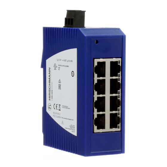
Page 17: Device View
a. For device variant SPIDER SL-40-06T1O6O699SZ9HHHH, the maximum permitted ambient air temperature has to be reduced to 122 °F (50 °C). Device view 1.3.1 Front view 11 11 11 11 SPIDER-SL-20-08T1... SPIDER-SL-20-06T1... SPIDER-SL-20-04T1... SPIDER-SL-20-01T1... Front view using example of device variants SPIDER-SL-20... SPIDER-SL-20-08T1... - Page 18 LED display elements for port status Rail lock slide for DIN rail mounting 11 11 11 11 11 11 SPIDER-SL-40-08T1... SPIDER-SL-40-05T1... SPIDER-SL-40-06T1... SPIDER-SL-40-06T1... Front view using example of device variants SPIDER-SL-40... SPIDER-SL-40-08T1... LED display elements for device status 3-pin, pluggable terminal block for power supply 3 ...
-
Page 19: Power Supply
Power supply 1.4.1 Supply voltage with the characteristic value HH The following options for power supply are available: 3-pin terminal block You will find information on connecting the supply voltage here: See “Connecting the 3-pin terminal block (device variants with characteristic value HH)”... -
Page 20: 10/100 Mbit/S Twisted Pair Port
1.5.2 10/100 Mbit/s twisted pair port This port is an RJ45 socket. The 10/100 Mbit/s twisted pair port allows you to connect network components according to the IEEE 802.3 10BASE-T/100BASE-TX standard. This port supports: Autonegotiation Autopolarity Autocrossing ... -
Page 21: Pin Assignments
Pin assignments RJ45 10/100 Mbit/s 1000 Mbit/s MDI mode BI_DA+ TX− BI_DA− BI_DB+ — BI_DC+ — BI_DC− RX− BI_DB− — BI_DD+ — BI_DD− MDI-X mode BI_DB+ RX− BI_DB− BI_DA+ — BI_DD+ — BI_DD− TX− BI_DA− — BI_DC+ — BI_DC− Display elements After the supply voltage is switched on, the device performs a self-test. -
Page 22: Port Status
Color Activity Meaning green lights up Supply voltage is on Device is ready for operation none Supply voltage is too low Device is not ready for operation 1.7.2 Port status These LEDs provide port-related information. Color Activity Meaning (link status/data) green lights up Device detects a valid link flashing... -
Page 23: Installation
Installation The devices have been developed for practical application in a harsh industrial environment. On delivery, the device is ready for operation. To install the device, perform the following work steps: Checking the package contents Mounting the device ... -
Page 24: Installing The Device Onto The Din Rail
2.2.1 Installing the device onto the DIN rail Prerequisite: The device is for mounting on a 35 mm DIN rail in accordance with DIN EN 60715. Perform the following work steps: Slide the upper snap-in guide of the device into the DIN rail. ... -
Page 25: Mounting On A Flat Surface
2.2.2 Mounting on a flat surface inch 57,5 2.26 1.65 24,25 0.95 35,75 1.41 inch 87,5 3.44 2.83 54,25 2.14 65,75 2.59 Perform the following work steps: Attach the wall mounting plate to a flat surface of the wall using screws. You will find the dimensions necessary for mounting the device in the illustration. -
Page 26: Installing An Sfp Transceiver (Optional)
Installing an SFP transceiver (optional) Prerequisites: Exclusively use Hirschmann SFP transceivers. See “Accessories” on page 38. Figure 1: Installing SFP transceivers: Installation sequence Perform the following work steps: Take the SFP transceiver out of the transport packaging (1). Remove the protection cap from the SFP transceiver (2). ... -
Page 27: Connecting The 3-Pin Terminal Block (Device Variants With Characteristic Value Hh)
The shielding ground of the connectable twisted pair cables is connected to the ground connection as a conductor. 2.4.1 Connecting the 3-pin terminal block (device variants with characteristic value HH) Figure 2: 3-pin terminal block, characteristic value HH Type of the voltages Specification of the supply Pin assignment that can be... -
Page 28: Connecting The 3-Pin Voltage Terminal With Spring (Device Variants With The Characteristic Value Hk)
Fasten the wires in the terminal block by tightening the terminal screws. Mount the terminal block for the supply voltage and the ground by plugging them in. 2.4.2 Connecting the 3-pin voltage terminal with spring (device variants with the characteristic value HK) Figure 3: 3-pin voltage terminal with spring, characteristic value HK Type of the voltages Specification of the supply... -
Page 29: Operating The Device
Open the terminal lock by pressing the corresponding lever with a screwdriver. Connect the wires according to the pin assignment on the device with the clamps. Mount the terminal block for the supply voltage and the ground by plugging them in. -
Page 30: Monitoring The Ambient Air Temperature
Monitoring the ambient air temperature Operate the device below the specified maximum ambient air temperature exclusively. See “General technical data” on page 34. The ambient air temperature is the temperature of the air at a distance of 5 cm (2 in) from the device. It depends on the installation conditions of the device, for example the distance from other devices or other objects, and the output of neighboring devices. -
Page 31: Maintenance And Service
Maintenance and service When designing this device, Hirschmann largely avoided using high-wear parts. The parts subject to wear and tear are dimensioned to last longer than the lifetime of the product when it is operated normally. Operate this device according to the specifications. Depending on the degree of pollution in the operating environment, check at regular intervals that the ventilation slots in the device are not obstructed. -
Page 32: Disassembly
Disassembly Removing an SFP transceiver (optional) Figure 4: De-installing SFP transceivers: De-installation sequence Perform the following work steps: Open the locking mechanism of the SFP transceiver (1). Pull the SFP transceiver out of the slot via the open locking mechanism (2). -
Page 33: Removing The Device
Removing the device Perform the following work steps: Disconnect the data cables. Disable the supply voltage. Remove the terminal connector from the device. Use a screwdriver to pull the rail lock slide downwards. Pull the device downwards from the DIN rail module. Installation SPIDER-SL Release 07 05/2022... -
Page 34: Technical Data
Technical data General technical data Dimensions SPIDER Standard Line See “Dimension drawings” on W × H × D page 35. Weight SPIDER-SL-20-01T1... 120 g (4.23 oz) SPIDER-SL-20-04T1... 130 g (4.59 oz) SPIDER-SL-20-06T1M29... 225 g (7.94 oz) SPIDER-SL-20-06T1S29... 225 g (7.94 oz) SPIDER-SL-20-06T1M2M... - Page 35 Dimension drawings 14,3 14,3 13,8 14,3 inch 25,5 25,5 37,8 SPIDER-SL-20-06T1... SPIDER-SL-20-08T1... SPIDER-SL-20-01T1... SPIDER-SL-20-04T1... Figure 5: Dimensions of device variants SPIDER-SL-20... 13,8 13,8 14,3 14,3 inch 25,5 37,8 SPIDER-SL-40-06T1... SPIDER-SL-40-06T1... SPIDER-SL-40-08T1... SPIDER-SL-40-05T1... Figure 6: Dimensions of device variants SPIDER-SL-40... Installation SPIDER-SL Release 07 05/2022...
- Page 36 EMC and immunity Note: Use shielded data cables for gigabit transmission via copper cables. Use shielded data cables for all transmission rates to meet the requirements according to EN 50121-4 and marine applications. EMC interference emission Radiated emission FCC 47 CFR Part 15 Class A EN 55032 Class A...
- Page 37 Network range 10/100/1000 Mbit/s twisted pair port Length of a twisted pair segment max. 100 m (328 ft) (for Cat5e cable) Table 4: Network range: 10/100/1000 Mbit/s twisted pair port Power consumption/power output at 24 V DC Device name Max.
- Page 38 Device Order number SPIDER-SL-40-06T1O6O699SZ9HHHH 942-132-015 SPIDER-SL-40-08T1999999SYZ9HHHH 942-132-004 Accessories Note that products recommended as accessories may have different characteristics to those of the device, which may limit the application range of the overall system. For example, if you add an accessory with IP20 to a device with IP65, the degree of protection of the overall system is reduced to IP20.
- Page 39 Gigabit Ethernet SFP transceiver Order number M-SFP-TX/RJ45 943 977-001 M-SFP-SX/LC 943 014-001 M-SFP-SX/LC EEC 943 896-001 M-SFP-MX/LC EEC 942 108-001 M-SFP-LX/LC 943 015-001 M-SFP-LX/LC EEC 943 897-001 M-SFP-LX+/LC 942 023-001 M-SFP-LX+/ LC EEC 942 024-001 M-SFP-LH/LC 943 042-001 M-SFP-LH/LC EEC 943 898-001 M-SFP-LH+/LC 943 049-001...
- Page 40 Underlying technical standards Name CSA C22.2 No. 142 Canadian National Standard(s) – Process Control Equipment – Industrial Products EN 50121-4 Railway applications – EMC – Emission and immunity of the signaling and telecommunications apparatus (Rail Trackside) EN 55032 Electromagnetic compatibility of multimedia equipment – Emission Requirements EN 61000-6-2 Electromagnetic compatibility (EMC) –...
-
Page 41: A Further Support
You find the addresses of our partners on the Internet at http://www.hirschmann.com. A list of local telephone numbers and email addresses for technical support directly from Hirschmann is available at https://hirschmann-support.belden.com. This site also includes a free of charge knowledge base and a software download section. Customer Innovation Center...
Need help?
Do you have a question about the Hirschmann SPIDER-SL-20-08T1999999SY9HHHH and is the answer not in the manual?
Questions and answers