
Related Manuals for Festo VAEM-V-S8EPRS2


Summary of Contents for Festo VAEM-V-S8EPRS2
- Page 1 VAEM-V-S8EPRS2 Valve control module Operating instructions 8127480 8127480 2020-07 [8127482]...
- Page 2 Translation of the original instructions ® ® CODESYS , MODBUS are registered trademarks of the respective trademark owners in certain coun- tries. Festo — VAEM-V-S8EPRS2 — 2020-07...
-
Page 3: Table Of Contents
Configuration parameters per valve................24 Cleaning........................25 Malfunctions....................... 25 Diagnostics........................25 Fault clearance......................26 9.2.1 Resetting the active error bit...................26 9.2.2 System faults......................26 9.2.3 Valve faults......................26 9.2.4 Communication errors.................... 27 Disposal........................28 Technical data......................28 Festo — VAEM-V-S8EPRS2 — 2020-07... -
Page 4: Applicable Documents
Applicable documents Applicable documents All available documents for the product è www.festo.com/sp. Documents Product Contents Brief instruction valve control module Installation, Parameterisation VAEM-V-S8EPRS2 – Assembly instruc- H-rail mounting VAME-V3-H tions Application Note valve control Connection via Ethernet in CODESYS module VAEM-V-S8EPRS2... -
Page 5: Additional Information
– Accessories è www.festo.com/catalogue. Service Contact your regional Festo contact person if you have technical questions è www.festo.com. Product overview The product is an electronic control with integrated, adjustable holding current reduction for con- trolling solenoid valves. Communication takes place via a COM interface using the ASCII protocol or via an Ethernet interface using the Modbus TCP protocol in accordance with the client-server principle. -
Page 6: Holding Current Reduction
– Reduction of the heat development of the solenoid valve coil – Increased service life of solenoid valves – Lower power consumption – Improvement of the switching times of solenoid valves Festo — VAEM-V-S8EPRS2 — 2020-07... -
Page 7: Product Design
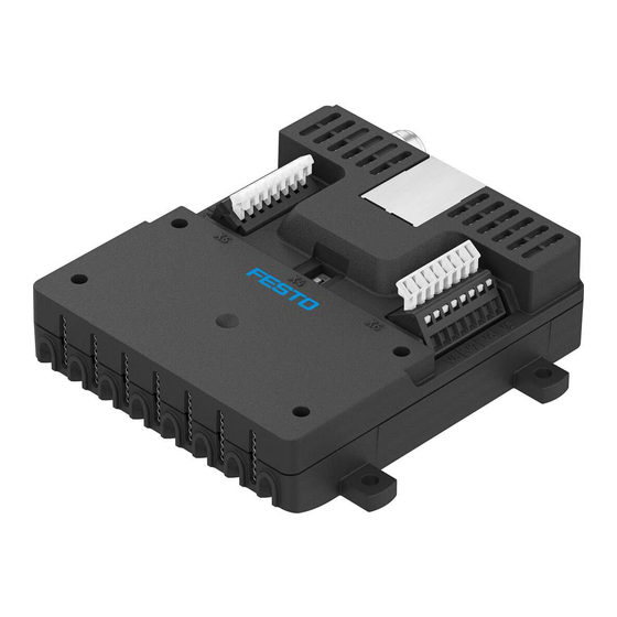
8 Switch [X4]: baud rate 9 Terminal [X6]: valves 5 … 8 Fig. 3 Product design and connections 5.2.1 Control elements Switch [X4] The transmission speed of the communication interface [X3] is set at switch [X4]. Festo — VAEM-V-S8EPRS2 — 2020-07... -
Page 8: Connecting Elements
Tab. 4 Pin allocation connection [X1] Ports [X5] and [X6] The connections [X5] and [X6] are each provided with a terminal to connect the valves. Plug pattern Function terminal [X5] Connection valve 1 Connection valve 2 Festo — VAEM-V-S8EPRS2 — 2020-07... -
Page 9: Commissioning
Connection valve 5 Tab. 5 Pin assignment of terminals [X5] and [X6] Port [X2]: Ethernet The port [X2] in the version VAEM-V-S8EPRS2 is a TCP/IP communication interface via Ethernet. Port [X3]: RS232 The port [X3] is for communications via the RS232 interface. -
Page 10: Connection Settings
ASCII telegrams via RS232 – Modbus TCP/TCP protocol via Ethernet In order to communicate with the VAEM-V-S8EPRS2 via RS232, serial terminal software is required to transmit the ASCII telegrams. Connection settings via an RS232 connection Connection settings are required to use the product with the serial interface module [X3] and terminal software. -
Page 11: Parameterisation
8 bit unsigned … integer Tab. 10 Data types Ethernet system parameters Function Index ASCII abbreviation HEX value controllword Index 1 statusword Index 2 Saving parameter val- Index 11 nominal voltage Index 4 inrush current Index 5 Festo — VAEM-V-S8EPRS2 — 2020-07... - Page 12 è required. Invalid IP addresses: – 0.x.x.x – 127.x.x.x – 224.x.x.x – 255.255.255.255 IPV4AddressIst 61 Uint32 0 3232281089 Display destination IP 429496729- (decimal) address in the network … 4 (decimal) Festo — VAEM-V-S8EPRS2 — 2020-07...
-
Page 13: Architecture Ascii Telegram
Identification area The identification area consists of the index and the subindex. The index denotes the system paramet- er. The subindex denotes the addressing at which the function of the system parameter is to be executed. Festo — VAEM-V-S8EPRS2 — 2020-07... -
Page 14: Architecture Of Modbus Tcp
4 Number of following bytes 2 Protocol identifier 5 Device identification Fig. 6 Modbus TCP header Byte Num- Designation Description Byte order ber of bytes Transaction number Freely selectable most significant byte least significant byte Festo — VAEM-V-S8EPRS2 — 2020-07... - Page 15 Number of registers 0x0007 (default value) most significant byte read least significant byte Start address of the 0x0000 (default value) most significant byte write registers least significant byte Festo — VAEM-V-S8EPRS2 — 2020-07...
- Page 16 Highest-value byte Tab. 11 Parameter listing è Lowest-value byte index with abbreviations Tab. 31 Valve control è functions Subindex Addressing of the function at system or valve level Tab. 12 Listing of è subindex and addressing Festo — VAEM-V-S8EPRS2 — 2020-07...
-
Page 17: Parameter Description
1 0 à (only possible in operating mode 1) Reset error Normal status Stops the operation of all selected valves message and resets the active error bit in the status word Festo — VAEM-V-S8EPRS2 — 2020-07... - Page 18 (Ethernet communication) value must be converted into a binary code. The individual digits of the binary code represent the individual status indicators from right to left. The individual bits are shown in the table from top to bottom. Festo — VAEM-V-S8EPRS2 — 2020-07...
- Page 19 Example of data area Modbus TCP type paramet- ing para- value ers index meter subindex 0x00 0x02 0x02 0x00 0x00 00 02 0002 00 00 0000 0000 (read) (Uint16) 0000 0000 Tab. 22 Architecture of Modbus TCP: query status word Festo — VAEM-V-S8EPRS2 — 2020-07...
- Page 20 The product can be operated in three different modes. They differ in cycle time, cycle start and trigger. Fig. 9 Current curve and signal level in operating mode 1 Fig. 10 Current curve and trigger voltage in operating mode 2 Festo — VAEM-V-S8EPRS2 — 2020-07...
- Page 21 0x01 0x01 0x09 0x00 0x00 01 01 0009 00 00 0000 0000 (write) (Uint08) 0x01 0000 0001 0x02 Tab. 26 Architecture of Modbus TCP: set operating mode Festo — VAEM-V-S8EPRS2 — 2020-07...
- Page 22 Fig. 12 Valve assignment in binary code Access Data type Index I Subindex S Value V Example of an ASCII tele- gram WU08:I19S0V89 (selected valves 1, 4, 5 and 7) Tab. 27 Architecture of the ASCII telegram: select valve Festo — VAEM-V-S8EPRS2 — 2020-07...
- Page 23 The following configuration parameters are saved: – nominal voltage – inrush current – holding current – response time – pickup time – operating mode – selected valves – time delay – hit-and-hold actuation time Festo — VAEM-V-S8EPRS2 — 2020-07...
-
Page 24: Configuration Parameters Per Valve
RU32:I7Sy time set delay time uint32 0.2 ms … WU32:I22Sy read delay time uint32 0.2 ms RU32:I22Sy set pickup time uint16 0.2 ms 1 … 500 WU16:I8SyVx read pickup time 8 uint16 0.2 ms RU16:I8Sy Festo — VAEM-V-S8EPRS2 — 2020-07... -
Page 25: Cleaning
– Operating voltage 2. Clean the outside of the product with a soft cloth. Do not use aggressive cleaning agents. Malfunctions Diagnostics LED green LED red Description Error-free operation Device identification failed Error is present Festo — VAEM-V-S8EPRS2 — 2020-07... -
Page 26: Fault Clearance
0001 00 00 0000 0000 0000 0008 9.2.2 System faults In the event of a system fault, all selected valves are deactivated in the status word. The red LED flashes and error bit 3 in the status word becomes active. Festo — VAEM-V-S8EPRS2 — 2020-07... -
Page 27: Valve Faults
Check the current consump- valve exceeds permissible – During the operating time tion of the valve value of the valves – Error in case of current – Valve short-circuit consumption during tightening phase 1.35 A > Festo — VAEM-V-S8EPRS2 — 2020-07... -
Page 28: Communication Errors
Check and correct the ASCII structure of the input Syntax error index (variable x) Check and correct index and value Syntax error subindex (variable y) Check and correct subindex and value Syntax error value Check and correct value Festo — VAEM-V-S8EPRS2 — 2020-07... -
Page 29: Disposal
Shock test with severity level 2 in accordance with EN 60068-2-6 (FN 942017-4) shock resistance Shock test with severity level 2 in accordance with EN 60068-2-27 (FN 942017-5) note on materials Contains PWIS substances Cable length Valve £ RS232 £ Power supply £ Ethernet £ Festo — VAEM-V-S8EPRS2 — 2020-07... - Page 30 27 58 27 60 0.15 0.35 … … ± ± – – 58 160 60 160 … … – – 160 200 160 200 … … Shock load Acceleration [m/s Duration [ms] Shocks per direction Festo — VAEM-V-S8EPRS2 — 2020-07...
- Page 31 Technical data Type of severity level (SL) ± ± Continuous shock load Acceleration [m/s Duration [ms] Shocks per direction 1000 ± Tab. 38 Type of severity level (SL) Festo — VAEM-V-S8EPRS2 — 2020-07...
- Page 32 Festo SE & Co. KG Ruiter Straße 82 73734 Esslingen Germany Phone: +49 711 347-0 Internet: www.festo.com © 2020 all rights reserved to Festo SE & Co. KG...
Need help?
Do you have a question about the VAEM-V-S8EPRS2 and is the answer not in the manual?
Questions and answers