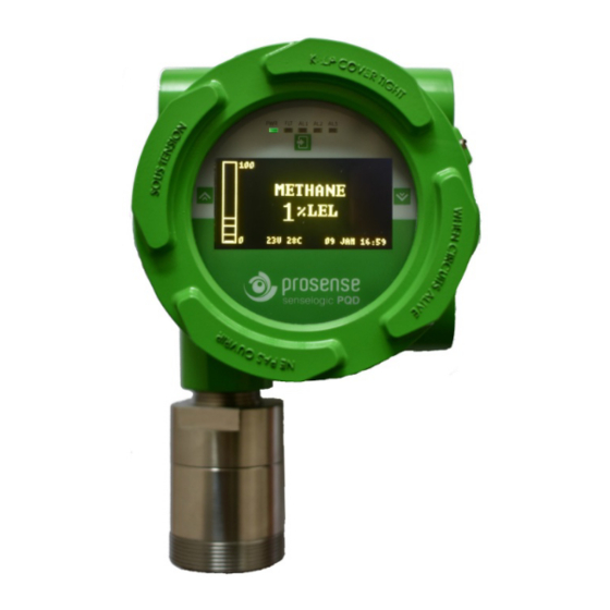
Prosense PQ Series Installation And User Manual

Prosense PQ Series Installation And User Manual

Hide thumbs Also See for PQ Series:
Table of Contents

Advertisement

PROSENSE PQ Series Gas Detectors
Installation and User Manual
Prosense Teknoloji San. Ltd. Şti.
Yukarı Mah. Harman sok. No:42 Kartal İstanbul
Tel: (90) 216 306 77 88 Faks: (90)216 473 81 29
www.prosense.com.tr
PRS-UM-PQ-EN-Rev.05-18.06.2020
1

Advertisement

Table of Contents
loading

Summary of Contents for Prosense PQ Series

  • Page 1 PROSENSE PQ Series Gas Detectors Installation and User Manual Prosense Teknoloji San. Ltd. Şti. Yukarı Mah. Harman sok. No:42 Kartal İstanbul Tel: (90) 216 306 77 88 Faks: (90)216 473 81 29 www.prosense.com.tr PRS-UM-PQ-EN-Rev.05-18.06.2020...
  • Page 2 Otherwise, it could fail to perform as designed and persons who rely on this product for their safety could suffer severe personal injury or death. The warranties made by Prosense with respect to this product are voided if the product is not installed, used and serviced in accordance with the instructions in this user guide.
  • Page 3: Table Of Contents

    Contents Safety Information............................5 Strictly follow the Instructions for Use ....................5 Maintenance ............................5 Use in areas subject to explosion hazards ..................5 Liability for proper function or damage ..................... 5 Intended Use ............................6 Introduction ..............................8 Detector body ............................11 Sensor Head..............................
  • Page 4 Test Menu Options ..........................36 Run Inhibit test ..........................36 Run Display test ..........................37 Run Relay test ........................... 37 Run Analogue Output test ........................ 38 Run Bump Test ..........................38 Calibration ..............................40 Set Reference Gas details ........................41 Set Calibration Cycle ..........................
  • Page 5: Safety Information

    Prosense or if the sensing head is used in a manner not conforming to its intended use. Prosense cannot be held responsible for damage caused by non-compliance with the recommendations given above.
  • Page 6: Intended Use

    2G. Thus this detector is suitable to be operated in hazardous areas with potentially explosive atmospheres of zone 1 and zone 2. The PQ series detector comprises a gas sensor type Ex- proof (protection type flameproof enclosure db type). PQ Series detector for flammable gases performs % 0 to % 100 LEL measurement range;...
  • Page 7 1. Very high gas concentrations The measuring method of PQ series detector based on heat produced by reaction on the oxidation of a flammable gas when pellistor sensor used. There is not enough oxygen in the sensor to perform oxidation process correctly in case of high gas concentrations. Hence the measuring signal decreases at high gas concentrations and even can lead to measuring signal within the measuring range again.
  • Page 8: Introduction

    PQ Series gas detectors for monitoring a very wide range of toxic and flammable gases and oxygen. PQ series are available as Flameproof (Ex db) detectors suitable for use in Zone 1 or 2 hazardous areas. Please refer to the certification label on the detector junction box to identify the type of certification that relates to the product supplied.
  • Page 9 Label A Label B * Label C * Diagram1: PQ Series Detector labels Label A: Product definition Label B: Product label based on ATEX and IECEx directives Label C: Group I Product label XXXX is the four digit NB number issuing current QAN and QAR...
  • Page 10 Directive 2014/34/EU and marked by the device category II 2G. Thus this detector is suitable to be operated in hazardous areas with potentially explosive atmospheres of zone 1 and zone 2. The PQ series detector comprises a gas sensor type Ex-proof (protection type flameproof enclosure db type).
  • Page 11: Detector Body

    Detector body The detector enclosure has four threaded entries. The two cable entries either side of the upper part of the transmitter housing are for connecting the power source, signal output and relay contacts to associated signalling equipment. The bottom entry allows direct connection of the sensor socket.
  • Page 12: Sensor Head

    Sensor Head Table 1: Detector body types and entry specifications The Prosense sensor head designed to detect flammable, toxic and oxygen gases. Sensor head may include Infrared, pellistor and a wide range of toxic gas sensors based on electrochemical cell (ECC) technology.
  • Page 13 Prosense may provide cable gland together with detector in regards to customer requests. The cable gland provided by Prosense has ATEX certification and provides at least IP65 level protection. The cable glands are only suitable for fixed installations. Cable gland body should be fixed to related entry with 20Nm torque.
  • Page 14: Mounting The Detector

    • in places where temperature is outside the admissible operating range, • corrosive environments, • inside air vents. • environments where silicon can be found. Prosense PQ series detector has mounting two mounting holes on detector body to fix detector directly to a surface: Mounting hole Mounting hole Diagram 6: Mounting holes PRS-UM-PQ-EN-Rev.05-18.06.2020...
  • Page 15: Electrical Connections

    Caution: All electrical connections should be made in accordance with any relevant local or national legislation, standards or codes of practice. Prosense detectors can operate between 12 - 24 VDC. The connection socket located on main board as given in Diagram-11 (page 19) and details given in below table 2:...
  • Page 16 Minimum power consumption of the detector without any optional module is 1W. The current required to drive the detector at the minimum voltage is (I = P / V) : 1.0 / 12 = 85mA (I detector). Maximum power consumption of the detector when optional relay modules installed and all relays are active is 4.0W.
  • Page 17: Cabling

    Cabling The use of industrial grade, suitably shielded field cable is recommended. The best practices shown that, screened 3 cores (plus screen 90% coverage), suitably mechanically protected copper cable with a suitable explosion-proof gland, or ¾” NPT steel conduit, depending on the distance between signal received or control panel and detector 0.5 to 2.5 mm2 (20 to 13 AWG) conductors can give better results.
  • Page 18: Detector Grounding

    Detector grounding Internal Ground connection: Each detector has grounding screw which utilizes grounding for detector main PCB to detector body. The screw should be located correctly and fixed for all times. In case of any maintenance activity this screw should be checked and fixed to make sure for proper grounding.
  • Page 19: Default Configuration

    Default configuration Prosense detectors preconfigured to provide signal from analogue output depending on the detector and gas type: Function Value/Setting Meaning 2.0 mA Fault 2.0 mA to 3 mA Warm-up Signal output Calibration mode 4.0 mA to 20.0 mA Normal gas measurement 21.0 –...
  • Page 20: Detector Configuration

    RS485 serial communication output: mode resulting with reducing signal level to 2mA. Prosense PQ series detector has RS485 serial communication output on main board. Connection ports are located on a different socket nearby analogue output and power input ports. User should prepare two wire additional cables when RS485 communication used. To use the detector with RS485 serial communication, a four-wire connection should be done which are energy input (V +, V-) ports and RS485 (A, B) ports.
  • Page 21: Detector Relay Module

    RS485 termination pin shown on Diagram-11 once the Detector Relay module: installation completed. Prosense provides optional relay modules for Prosense PQ detectors. The relay module details are given below: Relay board connection socket Alarm level adjustment pins...
  • Page 22: Oxygen Detectors

    The relay module set to NO (Normally Open – De-Energised) position at factory. The Fault relay is set to NO (Normally Open – Energised). It will be de-energized in case of power failure. This helps user to easily identify any power outage on detector side. The alarm levels are also adjustable via using SW1 and SW2 alarm level pins.
  • Page 23: System Status

    System Status The Prosense PQ detector has a screen to show status messages and measurement levels online. Also it has five LEDs to show power, fault, alarm1, alarm2 and alarm3 status. If all is fine the green power LED will lit and screen will show the gas that detector measuring, current level of gas detector reading, data and time information, ambient temperature and a bar to show level of current gas measurement.
  • Page 24: Commissioning

    7. Check the screen. It will run self check tests and report the results. All tests should end with OK. In case of any ERROR message contact Prosense. 8. When test completed the screen will show monitoring screen with detector information and WARMUP message on status line.
  • Page 25: Commissioning Pqn

    Commissioning PQN 1. Remove the detector cover 2. Configure the detector's analogue output signal and power input connections correctly 3. Check that all electrical connections are terminated correctly 4. Switch On the external power supply to feed the detector 5. Using a Digital Multi Meter (DMM), check the Supply Voltage at the terminals V+ (24V) and V- (0V), this should be a minimum supply voltage of 12VDC (Maximum supply voltage is 24VDC) 6.
  • Page 26: Detector Settings

    Enter key till the screen return back to previous screen. PQN Series detectors will have same functions, options and screens when used with a hand terminal. The hand terminal provided by Prosense and can be used to setup or maintain the Entering the menu: detector.
  • Page 27: Menu Structure

    Menu structure PQ Detector menu includes all necessary steps to setup detector and display information. Alarm Settings Diagram 13: Main menu structure Alarm levels can be adjusted via using alarm menu steps. Alarm menu general structure is given in diagram-12: Diagram14: Alarm menu structure Once you reach the main menu the first option is alarm settings.
  • Page 28 Please select the alarm level you would like to adjust and press Enter key to see details. All alarm details will be listed in new screen and parameters will be blinking one by one while you set the values. Alarm 1 Settings Level: 10% Auto-reset: NO Directions: Rising...
  • Page 29: Configure

    Configure User can change the parameters of detector depending of the usage such as date, time, password and detector address via configure menu. Select ‘Configure’ step on main menu to perform changes. A new menu options will display with options: 1.
  • Page 30: Change Modbus Address

    The first digit on screen will start blinking once entered the menu step. You can increase or decrease the value via using up and down keys. Once desired value has been set press Enter key to confirm and move to the next digit to set. Once all set press Enter key. The display will show “Successful”...
  • Page 31: Change Language

    Change Language The detector display language can be changed to English or Turkish. To change Language first select Configure option on main menu then select Display option and Language option. Once you reach to Language screen you will able to switch display language: Menu Language English Change Zero Suppression...
  • Page 32: Detector Model

    Detector Model This menu step used to set detector model. PQ series detectors named as PQD if they have display module and PQN if they do not have display module. This menu step is used only at production and not necessarly to change at field at any time.
  • Page 33: Change Test Interval

    Change Test Interval To change bump test interval select Test Interval option on Bump Test Menu. Bump Test Interval 3 Month Once the bump test interval menu shown the time value will start blinking. User can change the value via using up and down keys. Select Enter key to save the value when adjustment done.
  • Page 34: Information Menu Options

    Information Menu options Information menu provides more detailed information about measurements, events and device itself. The Information menu structure is given in below diagram: Display Event Logs Diagram16: Information menu structure Detector records all events starting from its power-on. To display recorded events, select Event log option in Information menu.
  • Page 35: Display Measurements

    :300 Ohm Temperature :34C Display Transmitter information To get details about transmitter and firmware level use transmitter information step in Information menu. A screen will display details. Prosense Ltd. KS031 XMTR S/N:00021907 XMTR F/W:V.1.1.0 DSP F/W :V.1.1.1 Modbus Adr.:01 Test Due:18/12/2018 To return back to previous menu please press Enter key till the screen changes.
  • Page 36: Test Menu Options

    Test Menu Options User can execute tests to check detectors functions. Test menu structure is given in below diagram: Diagram17: Test menu structure To perform tests select Test menu item via up and down keys then press Enter key. The screen will display test options: 1.
  • Page 37: Run Display Test

    If user finish the work or test it is necessary to clear inhibit mode to return detector to normal operation. To do this user should re-enter to Inhibit menu in Test menu. The clear option will be displayed at this time: 1.
  • Page 38: Run Analogue Output Test

    To return back to previous screen please press Enter key till the screen updated with previous menu items. Run Analogue Output test To test analogue output level user can initiate the analogue output test in Test menu. Once Analogue Output option selected press Enter Key. Screen will display the analogue output level.
  • Page 39 Remove applied gas Detector will return to measurement screen for another 30 seconds with same message BUMP TEST METHANE 0 %LEL Remove applied gas Once the time counted down to zero the screen will display test results: Start Concentration 0%LEL Peak Concentration 24%LEL End Concentration...
  • Page 40: Calibration

    It is recommended to periodically carry out calibration to ensure correct operation. Prosense PQ series detector calibration includes two steps as zero and span calibration. It is possible to perform each step independently. Prosense recommends to perform both calibration steps to have correct calibration.
  • Page 41: Set Reference Gas Details

    If the password is wrong the display will return to measurement screen. The screen will display menu options when correct password entered at last digit: 1. Alarm Settings 2. Calibrate 3. Configure 4. Information 5. Test 6. Exit Select Calibration. Screen will show calibration options: 1.
  • Page 42: Set Calibration Cycle

    Once set, confirm value with Enter key and move to the next digit. Set Calibration Cycle Prosense recommends performing calibration with six months period. Hence this default value is set to detector in factory. Detector will be faulted when calibration period expire. If user wants to use different calibration period this should be set via using the option “Cal...
  • Page 43: Span Calibration

    During this time you should apply necessary gas for zero level. For catalytic, pellistor and electrochemical sensors use clean air gas, for infrared sensors use N2 gas. For more details contact Prosense. Detector will automatically perform zero calibration while gas applied to Span Calibration sensor during this period.
  • Page 44: Maintenance

    Typical life of a toxic gas sensor which made by electrochemical component is dependent on the application, frequency and amount of gas exposure. Under normal conditions (visual inspection in 3 months period and test/recalibration in 6 months period), the Prosense Servicing Oxygen and other toxic sensors have an expected life equal to or greater than 24 months.
  • Page 45: Sensor Replacement

    Sensor replacement: The Flammable Catalytic and Toxic ECC cells that are used with the Prosense Sensor Head have limited serviceable parts. Detector must be diagnosed by service personnel when they have reached the end of their operational life or faced with a fault to follow correct procedure.
  • Page 46: Sensor Pcb Replacement

    9- Fix the Locking grub screw Sensor head replacement: Prosense sensor head is a separate part that can be replaced. The sensor head includes integrated sensor, electronic device and sinter in it. PQ series sensor head is pre-calibrated and will start function immediately following the replacement. To replace sensor head:...
  • Page 47: Detector Transmitter Board Replacement

    11- Leave detector working at least 4 hours in clean air environment PQD Detector Display Module replacement: 12- Check detector calibration. Prosense PQD display board is a replaceable part. The replacement should be done via following steps: 1- Power-Off the detector via disconnecting power cable from control panel or supply...
  • Page 48: Detector Relay Module Replacement

    Detector Relay Module replacement: Prosense PQD relay module is a replaceable part. The replacement should be done via following steps: 1- Power-Off the detector via disconnecting power cable from control panel or supply 2- Open the detector cover 3- Remove display module from the mounting rails (PQN does not have display module) 4- Disconnect relay module output connections.
  • Page 49: Status Codes

    Status Codes: Fault Code Fault Text Fault Description 0x00 NO FAULT 0x10 SENSOR ERROR Sensor is in fault condition 0x11 NOT CONNECTED Sensor is not connected or one-wire communication doesnot work. 0x12 SIGNAL OUT RANGE Sensor signal is out of range 0x13 TEMPERATURE ERR Temperature is out of range...
  • Page 50: Spare Parts

    Fault Code Fault Text Fault Description 0xB0 RELAY CARD ERR Relay module communication error 0xB1 FAULT RELAY ERR Fault relay is not functioning 0xB2 ALARM_1 RELAY ERR Alarm1 relay is not functioning 0xB3 ALARM_2 RELAY ERR Alarm2 relay is not functioning Spare Parts Product Code Description...
  • Page 51 UPY-05S-65 PQ Series Oxygene Sensor, 0-25% Vol UPY-05S-66 PQ Series Sulfur Dioxide Sensor, 0-10 ppm UPY-05S-67 PQ Series Nitric Oxide Sensor , 0-250 ppm UPY-05S-68 PQ Series Nitrogen Dioxide Sensor, 0-30 ppm UPY-05S-69 PQ Series Chlorine Dioxide Sensor, 0-10 ppm...
  • Page 52: General Specification

    General specification Use: 3-wire, 4-20mA or 4-wire RS485, gas detector transmitter for use with directly installed flammable and toxic gas sensors. For the protection of personnel and plant from flammable and toxic gas hazards. Electrical Specifications: Input Voltage Range 12 to 24VDC (24VDC nominal) Max Power Consumption Max 4 Watts.
  • Page 53: Safety Instructions For Hazardous Area Installation

    Read this instruction first and keep this instruction manual always available. The following instructions apply to equipment covered by ATEX certificate number: 1. Prosense PQ series gas detectors may be installed in hazardous area with flammable gases, vapours, and mist, group II, category 2G, maximum superficial permissible temperature 70°C.
  • Page 54 14. All electrical connections should be made in accordance with any relevant local or national legislation, standards or codes of practice. Prosense detectors can operate between 12 - 24 VDC. The connection, grounding, cabling details are explained in this guide at relevant sections PRS-UM-PQ-EN-Rev.05-18.06.2020...
  • Page 55: Certificate

    Certificate PRS-UM-PQ-EN-Rev.05-18.06.2020...
  • Page 56 PRS-UM-PQ-EN-Rev.05-18.06.2020...
  • Page 57 PRS-UM-PQ-EN-Rev.05-18.06.2020...
  • Page 58: Declaration

    Declaration PRS-UM-PQ-EN-Rev.05-18.06.2020...
  • Page 59: Warranty Statement

    Prosense Technology's liability for any claims arising out of or related to this product will in no case exceed the order value. To the extent permitted by applicable law, these limitations and exclusions will apply regardless of whether liability arises from breach of contract, warranty, tort (including but not limited to negligence), by operation of law, or otherwise.

This manual is also suitable for:

PqdPqn

Table of Contents