Prosense PQ Series Quick Installation Manual
Hide thumbs
Also See for PQ Series:
- Installation and user manual (59 pages) ,
- User manual (22 pages) ,
- User manual (8 pages)
Advertisement
Quick Links
Prosense PQ Series Quick Installation Guide
Detector connections
Prosense detectors preconfigured to provide signal from analogue output depending on
the detector and gas type:
Function
Signal output
Detector Main board and connection details given in Diagram‐1:
Power LED
Relay Module
Connections
Battery
Sensor connections are input to detector main board and already connected to sensor
inside the sensor head. Detector connections are listed in Table‐2:
Port
RS485‐A
RS485‐B
PRS‐QIG‐PQ‐EN‐Rev.01‐11.2018
Value/Setting
2.0 mA
2.0 mA to 2.5 mA
3mA
4.0 mA to 20.0 mA
21.0 mA
Table 1: Detector signal level details
Sensor Connections
Diagram 1: Detector main board and connections
Usage
V +
Power input (+) 12VDC – 24VDC
V ‐
Power input (‐) 12VDC – 24VDC
S
Current Output Signal (4mA – 20mA)
Serial connection port A
Serial connection port B
Table 2: Detector output ports and their usage
Meaning
Fault
Warm‐up
Calibration mode
Normal gas measurement
Maximum over range
RS485 termination pins
Display module
Connections
S
V‐
V+
RS485‐B
RS485‐A
Advertisement

Related Manuals for Prosense PQ Series


Summary of Contents for Prosense PQ Series
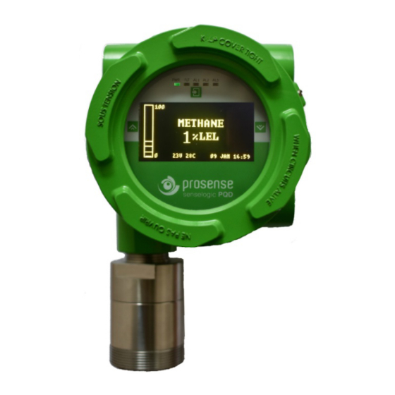
- Page 1 Prosense PQ Series Quick Installation Guide Detector connections Prosense detectors preconfigured to provide signal from analogue output depending on the detector and gas type: Function Value/Setting Meaning 2.0 mA Fault 2.0 mA to 2.5 mA Warm‐up Signal output 3mA Calibration mode 4.0 mA to 20.0 mA Normal gas measurement 21.0 mA Maximum over range Table 1: Detector signal level details Detector Main board and connection details given in Diagram‐1: Power LED S V‐ Relay Module Connections V+ RS485‐B Battery RS485‐A RS485 termination pins Display module Connections ...
- Page 2 Prosense PQ Series Quick Installation Guide Detector Configuration The Prosense PQ detector has 4‐20mA analogue output and RS485 Modbus serial communication output features on main board. It is possible to install optional relay module to have three relay outputs for two alarm levels and fault status. 4‐20 mA output: The default configuration provides single 4‐20mA signal output. Prosense detectors can be connected to control panels on the market having 4‐20mA input signal. Signal wiring from detector and the control panel should be carried out by shielded cables. Wires cross section depends on the distance between the control panel and the detector. The details given in power cabling are valid as well for signal output. Please avoid any interruption in case any junctions on wires. The shield is to be grounded from the control panel side only and never connect the shield to the detector. Please make sure clutching or crimping apparatus are not loosen or oxidized. To get the analogue output signal correctly and constant the load resistor on S output should be between 100‐500 Ohms if the power source is greated than 15VDC (15‐24 VDC) at detector input. If the power source is below 15VDC (12‐15 VDC) the load resistor on S output should be between 100‐300 Ohms. If the load resistor below 100 Ohms the detector will behave as the S output is in short circuit status and enable the automatic output saving mode resulting with reducing signal level to 2mA. Commissioning WARNING: The following procedure should be followed carefully and only performed by suitably trained personnel. The following procedure requires the detector cover to be removed while carrying out supply voltage checks. Therefore, the appropriate permits to work should be sought in preparation. Prior to carrying out any HOT WORK ensure local security and site procedures are followed. Ensure that the associated control panel output actuation is inhibited so as to prevent false alarms. Follow below steps for commissioning: 1. Remove the detector cover 2. Configure the detector's analogue output signal and power input connections correctly 3. Check that all electrical connections are terminated correctly 4. Switch On the external power supply to feed the detector 5. Using a Digital Multi Meter (DMM), check the Supply Voltage at the terminals V+ (24V) and V‐ (0V), this should be a minimum supply voltage of 12VDC (Maximum supply ...
- Page 3 Prosense PQ Series Quick Installation Guide completed LCD screen will show monitoring screen with detector information and WARMUP message on status line. The Fault LED is lit in this period. 8. Wait two minutes to complete warm‐up period. If using PQD, WARMUP message will be removed from status line and fault LED gone off. The LED on main board will start blinking once in a second and analogue output signal will be 4mA. 9. Switch Off the external power to the detector. 10. Fit the cover and make sure none of the cables cause an obstruction while fitting cover 11. Switch on external power to the detector. Electrical Specifications: Input Voltage Range 12 to 24VDC (24VDC nominal) Max Power Consumption Max 4 Watts. at 24VDC Current output 4‐20mA 2.0 mA Fault 2.0 mA to 2.5 mA Inhibit (during configuration/warming) 3mA Calibration mode 4.0 mA to 20.0 mA Normal gas measurement 21.0 mA Maximum over range Terminals 3 x screw terminals suitable for wire diameter 0.5 mm² to 2.5 mm² (20AWG to 13AWG). 2 x screw terminals suitable for wire diameter 0.5 mm² to 2.5 mm² (20AWG to 13AWG) for RS485 digital output Relays 3 x (1A 30VDC, 0.5A 125VAC, 0.3A 80VDC). Selectable normally open or normally closed (switch) and de‐energized. Communication RS485, Modbus RTU ...
- Page 4 Prosense PQ Series Quick Installation Guide SAFETY INSTRUCTIONS FOR HAZARDOUS AREA INSTALLATION Prosense PQ series gas detectors are projected and built according to ATEX Directive 2014/34/EU with reference to standard EN 60079‐0, EN 60079‐1. “ATEX“, by the French "ATmosphere EXplosible”, provides the technical requirements to be applied to equipment intended for use in potentially explosive atmospheres. The scope of directive is to remove technical barriers to trade between Member States of the European Community. The Prosense PQ series gas detectors must be installed and maintenance according to the suitable standards for electrical application in potentially explosive atmospheres (example: EN 60079‐14, EN 60079‐17 or other national standards). Read this instruction first and keep this instruction manual always available. The following instructions apply to equipment covered by ATEX certificate number: 1. Prosense PQ series gas detectors may be installed in hazardous area with flammable gases, vapours, and mist, group II, category 2G, maximum superficial permissible temperature 70°C. Device category 2G, Identification II 2G Ex db IIC T6 Gb (Tamb = ‐20°C : +70°C) It means: (European Community logo for ATEX applications) – group II (potentially explosive atmospheres – surface application – OTHER than mines) Category 2G ( G => Gas ) – Zone 1 and Zone 2 Ex db => protection mode: explosion proof enclosure IIC => define kind of gases T6 => Temperature class ‐‐ Maximum allowable surface temperature. IP 65 => Mechanical protection degree – protection against solid, dust and liquid. 2. Suitably trained personnel shall carry out installation in accordance with applicable code practice. 3. The electrical devices must be grounded using their grounding connections. The grounding connection must be ATEX certified, suitable for the application required, substances, maximum superficial temperature, and ambient temperature. 4. The user should guarantee periodical cleaning of the places were dust can storage to avoid the paling up to 5 mm. 5. The user should not repair this equipment. 6. The user should guarantee the keeping of the safety characteristic of the device after maintenance of ...
Need help?
Do you have a question about the PQ Series and is the answer not in the manual?
Questions and answers