
Related Manuals for WAGO 750-502


Summary of Contents for WAGO 750-502
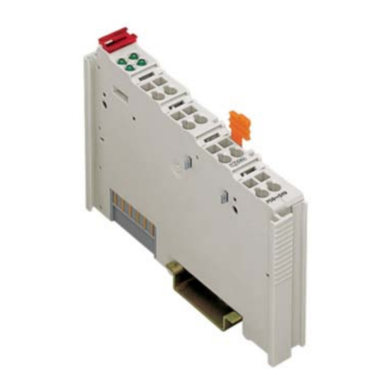
- Page 1 Fieldbus Independent I/O Modules 2 DO DC 24 V 2.0 A, High-Side Switching 750-502 Manual Version 1.0.3...
- Page 2 • General Copyright © 2006 by WAGO Kontakttechnik GmbH & Co. KG All rights reserved. WAGO Kontakttechnik GmbH & Co. KG Hansastraße 27 D-32423 Minden Phone: +49 (0) 571/8 87 – 0 Fax: +49 (0) 571/8 87 – 1 69 E-Mail: info@wago.com...
-
Page 3: Table Of Contents
Number Notation..................5 Safety Notes ..................... 6 Scope ......................6 2 I/O Modules ....................7 Digital Output Module ................7 2.1.1 750-502 [2 DO DC 24 V 2.0 A, High-Side Switching]....... 7 2.1.1.1 View....................7 2.1.1.2 Description..................7 2.1.1.3 Display Elements ................8 2.1.1.4... -
Page 4: Important Comments
WAGO Kontakttechnik GmbH & Co. KG declines all liability resulting from improper action and damage to WAGO products and third party products due to non-observance of the information contained in this manual. -
Page 5: Symbols
Routines or advice for efficient use of the device and software optimization. More information References on additional literature, manuals, data sheets and INTERNET pages 1.3 Number Notation Number Code Example Note Decimal normal notation Hexadecimal 0x64 C notation Binary '100' Within ', '0110.0100' Nibble separated with dots WAGO-I/O-SYSTEM 750 I/O Modules... -
Page 6: Safety Notes
1.5 Scope This manual describes the Digital Output Module 750-502 2 DO DC 24 V 2.0 A, High-Side Switching of the modular WAGO-I/O- SYSTEM 750. Handling, assembly and start-up are described in the manual of the Fieldbus Coupler. -
Page 7: O Modules
750-502 [2 DO DC 24 V 2.0 A, High-Side Switching] • 7 View 2 I/O Modules 2.1 Digital Output Module 2.1.1 750-502 [2 DO DC 24 V 2.0 A, High-Side Switching] 2-Channel Digital Output Module DC 24 V 2.0 A, short-circuit-protected, high-side switching 2.1.1.1 View... -
Page 8: Display Elements
Attention In case of overloads a supply module with fuse (750-601) must be connected on the line side to protect the output modules! The output module 750-502 can be used with all couplers/controllers of the WAGO-I/O-SYSTEM 750. 2.1.1.3 Display Elements... -
Page 9: Schematic Diagram
750-502 [2 DO DC 24 V 2.0 A, High-Side Switching] • 9 Schematic Diagram 2.1.1.4 Schematic Diagram DO 1 DO 2 270pF 10nF 10nF 10nF 750-501 Fig. 2.1.1-3: 2-Channel Digital Output Module 750-502 g050201e WAGO-I/O-SYSTEM 750 I/O Modules... -
Page 10: Technical Data
10 • 750-502 [2 DO DC 24 V 2.0 A, High-Side Switching] Technical Data 2.1.1.5 Technical Data Module Specific Data Number of outputs Current consumption (internal) 3.5 mA max. Voltage via power jumper contacts DC 24 V (-25 % ... +30%) -
Page 11: Process Image
750-502 [2 DO DC 24 V 2.0 A, High-Side Switching] • 11 Process Image Approvals (cf. Chapter 2.2 of the Coupler/Controller Manual) (UL508) ABS (American Bureau of Shipping) BV (Bureau Veritas) DNV (Det Norske Veritas) Cl. B GL (Germanischer Lloyd) Cat. - Page 12 WAGO Kontakttechnik GmbH & Co. KG Postfach 2880 • D-32385 Minden Hansastraße 27 • D-32423 Minden Phone: 05 71/8 87 – 0 Fax: 05 71/8 87 – 1 69 E-Mail: info@wago.com Internet: http://www.wago.com...
Need help?
Do you have a question about the 750-502 and is the answer not in the manual?
Questions and answers