Table of Contents
Troubleshooting

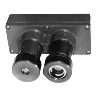
Related Manuals for Det-Tronics U7652


Summary of Contents for Det-Tronics U7652
- Page 1 Instructions 95-8385-06 Unitized UV/IR Flame Detector U7652 Detector Electronics Corporation 6901 West 110th Street • Minneapolis, Minnesota 55438 USA 3/01 95-8385-06 Tel: 952.941.5665 or 800.765.3473 • Fax: 952.829.8750...
-
Page 2: Table Of Contents
Relays and Outputs ..... . 2 Figure 2 U7652 Front View ....6 General Application Information ... . 3 Figure 3 Vertical Mounting . -
Page 3: Description
A pair of red LEDs is located inside each sensor view- care not to touch the terminals or electronic ing window (four LEDs per U7652 Detector). The two components. Observe the normal precau- LEDs for each sensor are illuminated simultaneously... -
Page 4: Relays And Outputs
— De-energizes when fault is detected. test does not produce an alarm condition. — Non-latching operation (automatically resets when fault is corrected). The U7652 can be programmed (using a jumper plug) for automatic and/or manually initiated test- U7652C Model ing. Use of automatic is highly recommended. -
Page 5: General Application Information
(one for also to know what other sources besides fire can each U7652 Detector in the system) and a W6300 cause the device to respond. Read through the fol- Detector Inspector™, which provides the interface lowing discussion of these factors before installing the between the electronic module and the PC. -
Page 6: Uv Absorbing Gases And Vapors
EMI/RFI INTERFERENCE attenuating substances include, but are not limited to, the following: The U7652 is resistant to interference by EMI and RFI. It will not respond to a 5 watt walkie-talkie at a dis- — silicones tance of greater than 1 foot. -
Page 7: Figure 1
FIELD OF VIEW not required by local wiring codes. A seal must be located as close to the U7652 as possible. In no case should this seal be located more than 18 inch- es (46 cm) from the unit. If a conduit swivel is used,... -
Page 8: Mounting And Wiring Procedure
BOTTOM OR SIDE TO Removed (Terminal Blocks, ELIMINATE DRAINAGE INTO JUNCTION BOX. C1327 Programming Jumpers, Motherboard Figure 2—U7652 Front View Assembly) Figure 5 — Detector Dimensions MOUNTING AND WIRING PROCEDURE Figure 6 — Swivel Mounting Bracket Dimensions Figure 7 —... -
Page 9: Detector Dimensions
3.38 (85.8 MM) 7.11 (181 MM) 2.5 DIA. (64 MM) 7.81 (198 MM) 5.25 (133 MM) C1047 CONDUIT ENTRY 3/4 NPT OR 25 MM Figure 5—Detector Dimensions CON 1 CON 2 SPARE SPARE FAULT* FAULT* JUNCTION BOX MOUNTING BRACKET (ATTACHES WITH TWO ENCLOSED FLATHEAD SCREWS) FIRE... -
Page 10: Wiring Terminal Configuration For U7652C With 4 To 20 Ma Output
CON 1 CON 2 Figure 8 — Wiring Terminal Configuration for – 4 TO 20 MA 4 TO 20 MA U7652C with Auxiliary Relay Figure 9 — Wiring Terminal Configuration for FAULT* FAULT* U7652C with 4 to 20 ma Output Figure 10—... -
Page 11: Detector Programming
DETECTOR PROGRAMMING Note that isolated operation requires the use of a sep- arate power supply. The U7652 provides three standard field pro- grammable options: 1. Mount the detector and mounting bracket assem- bly. The mounting surface should be free of —... -
Page 12: Startup And Checkout Procedure
MANUAL SELECTED (Jumper W2 Installed) or Failure During Startup and Checkout Procedure 3. Shine a Det-Tronics model W867 UV/IR test lamp (Manual Test) into the viewing window of the detector under test, or press and hold the manual... -
Page 13: Manual O I Test
The following field test procedure has been devel- Proper operation of the detector is indicated by simul- oped to test Det-Tronics UV/IR flame detectors for taneous blinking of both the UV and IR sensor LEDs ESD-damaged components: every 5 seconds. -
Page 14: Automatic O I Troubleshooting
Table 7—Automatic Troubleshooting Fault Indication Corrective Action UV Fault • Fault relay de-energized • Clean the viewing window and ring of the UV sensor. • UV sensor LEDs not blinking • Check the ring opening for proper orientation. See Figure 2. If the fault does not clear (UV fault reoccurs after approximately 3 minutes): •... -
Page 15: Sensor Module Replacement Procedure
Note that devices (see Figure 14 ), loosen the clamp and some Det-Tronics UV/IR detectors will provide a disengage the “catch” from the blind hole for the UV-only alarm that must not be confused with the appropriate sensor. -
Page 16: Figure 15 U7652 Detector Parts Identificaiton
TEST LAMP O-RING UV SENSOR HOUSING UV o i RING B1330 Figure 15—U7652 Detector Parts Identification • For the IR module, thread the wire leads and 10. Perform the “Startup and Checkout Procedure keyed connector plug through the slotted open- (Manual Test)”... -
Page 17: Motherboard Replacement Procedure
24 VDC – CONDUIT ENTRY NOTES • THIS ENHANCEMENT IS INSTALLED ON ALL NEW U7652 DETECTORS. IT IS RECOMMEDED THAT THIS ENHANCEMENT BE INSTALLED IN ALL EXISTING MODELS TO PROVIDE INCREASED EMI PROTECTION. 2 MEGOHM, 0.47 µf • PARTS REQUIRED: 0.47 MICROFARAD, 400 VOLT CAPACITOR AND A... -
Page 18: Maintenance
VIEWING WINDOWS/ RINGS • Relay outputs for fire and fault signals. The U7652 Detector requires no periodic calibration. • Optional 4 to 20 ma output available. However, to maintain maximum sensitivity, the detec- tor viewing windows must be kept clean at all times. -
Page 19: Figure 19 Uv And Ir Spectral Response Range
G; Class II/III, Division 2, Groups F and G SENSITIVITY— (T4A). The U7652 detects a 1 foot by 1 foot gasoline fire at Enclosure Type 4X 50 feet, a 2 foot by 2 foot JP4, 5, or 8 fire at 100 feet, and a 3 foot by 3 foot JP4, 5, or 8 fire at 150 feet. -
Page 20: Replacement Parts
CENELEC: Standard temperature version: REPLACEMENT PARTS EEx d IIB +H The electronic module is not designed to be repaired = –40°C to +75°C). in the field. If a problem should develop, first careful- EEx d IIB +H ly check for proper wiring and switch setting. If it is = –40°C to +90°C). -
Page 21: Ordering Information
ORDERING INFORMATION For assistance in ordering a system to fit your appli- cation, please contact: When ordering, specify: Detector Electronics Corporation U7652B UV/IR Detector 6901 West 110th Street U7652C UV/IR Detector with Auxiliary Relay Minneapolis, Minnesota 55438 USA U7652C UV/IR Detector with 4 to 20 ma output Operator: (952) 941-5665 or (800) 765-FIRE Customer Service: (952) 946-6491 Detector housing materials:... -
Page 22: Appendix A - Factory Mutual Research (Fmr) Approval Description
APPENDIX A - FACTORY MUTUAL RESEARCH (FMR) APPROVAL DESCRIPTION APPROVAL Models U7652B (relay output) and U7652C (relay or 4-20 ma output) with aluminum or stainless steel enclosure and 1/2-inch NPT conduit entries (M25 conduit entry may be used in non-North American applications). For 18- 32 vdc operation through an approved control panel that provides separate circuits for power and alarm initia- tion. - Page 23 Printed in USA Detector Electronics Corporation 6901 West 110th Street • Minneapolis, Minnesota 55438 USA Tel: 952.941.5665 or 800.765.3473 • Fax: 952.829.8750...
Need help?
Do you have a question about the U7652 and is the answer not in the manual?
Questions and answers