Table of Contents
Advertisement
DET
TRONICS
-
IMPORTANT
Be sure to read and understand the entire instruc-
tion manual before installing or operating the gas
detection system. This product is intended to pro-
vide early warning of the presence of a flammable
or explosive gas mixture. Proper device installa-
tion, operation, and maintenance is required to
ensure safe and effective operation.
APPLICATION
The Open Path Eclipse
™
infrared gas detection system that provides continuous
monitoring of combustible hydrocarbon gas concentra-
tions in the range of 0 to 5 LEL-meters. Standard sys-
tem outputs include an electrically isolated/non-isolated
4-20 mA dc current output, with HART communication
and RS-485 MODBUS communication.
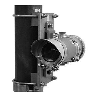
The system consists of two stainless steel modules — a
transmitter and a receiver, along with mounting fixture
hardware. Both modules are powered from an external
24 volt DC supply. The receiver provides the measure-
ment signal outputs, and is furnished with an onboard
"status indication" LED and an internal magnetic calibra-
tion switch. The transmitter houses redundant xenon
flashlamps. Both modules are installed at approximate-
ly the same elevation and must be aligned to point
directly at one another. No direct electrical interconnec-
tion between the two modules is required.
©
1.1
Detector Electronics Corporation 2004
®
Model OPECL is an open path
Infrared Hydrocarbon Gas Detector
The Open Path Eclipse is ideal for use in harsh outdoor
environments and is certified for use in Class I, Division
1 and Division 2 hazardous areas. It can be used as a
stand-alone detector, or as part of a larger facility pro-
tection system using other Det-Tronics equipment such
as the R8471 Series Controller or the Eagle Quantum
Premier Fire and Gas Detection/Releasing System.
INSTRUCTIONS
Open Path Eclipse
Model OPECL
1/04
™
95-8556
Advertisement
Table of Contents

Related Manuals for Det-Tronics OPECL


Summary of Contents for Det-Tronics OPECL
- Page 1 APPLICATION The Open Path Eclipse ™ Model OPECL is an open path infrared gas detection system that provides continuous monitoring of combustible hydrocarbon gas concentra- tions in the range of 0 to 5 LEL-meters. Standard sys-...
-
Page 2: Operation Overview
Gas type and other operational The OPECL transmitter module illuminates a direct lin- parameters are selected via digital communications. ear path ending at the OPECL receiver module. As The factory calibrated setting is methane. flammable hydrocarbon gases intersect the light beam... - Page 3 Table 1—Functional and Electrical Comparison of Transmitter and Receiver Characteristic Transmitter (Tx) Receiver (Rx) Functional Description Contains primary and backup xenon Contains opto-electronics, signal pro- flashlamps, and generates optical ener- cessing and output drivers, and diagnos- gy to enable hydrocarbon detection. tic electronics.
-
Page 4: Operating Modes
Table 2—Factory Default Settings Calibrate After alignment is completed, zero calibration is Default Options required. Fugure calibration of the OPECL is normally Gas Type Methane Methane, Ethane, not required; however, the user has the option to verify Propane, Butane proper calibration or to perform calibration procedures if necessary. -
Page 5: Specifications
Heated optics mitigate against ice and dew formation. Heater can be turned CALIBRATION— off for indoor applications or reduced power. OPECL systems are span calibrated for methane at the factory. WIRING— Field wiring screw terminals are UL/CSA rated for up to 14 AWG wire, and are DIN/VDE rated for 2.5 mm 2 wire. - Page 6 3 year limited warranty from date of manufacture. POST MOUNT FLAT SURFACE MOUNT SIDE VIEW OF TYPICAL OPECL 13.4 (43) (38) (34) (16.5) 16.5 (42) (33) OPTIONAL SUNSHADE MOUNTING POST B2251 FLEXIBLE CABLE Figure 2—Dimensions of OPECL in Inches (cm) 95-8556...
-
Page 7: Important Safety Notes
This product has been tested and approved for use in hazardous areas. However, it must be properly The OPECL system is designed for installation in haz- installed and used only under the conditions speci- ardous industrial areas. Each module is normally... - Page 8 Det-Tronics Field Service Engineering group routinely Snow and Ice in Ambients Below –20°C provides jobsite application surveys and analysis for The heated optics on both modules will melt snow or ice customers, and their services are highly recommended on the windows in ambient temperatures down to if guidance on optimum installation locations is required.
- Page 9 2 OPECL modules, supporting a minimum of 50 lbs (23 kg). See Figure 3. 2 module mounting brackets, • For flat surface mounting, the OPECL flat surface 2 pan-tilt plates, mount adapter is available. Ensure that the flat sur- face is capable of supporting a minimum of 100 lbs 4 U-bolts complete with (46 kg).
-
Page 10: Vdc Power Supply Requirements
3. Install the OPECL module onto the Mounting Plate. Tighten snugly to support the weight of the device. 4. Double check to ensure that the module is ade- quately supported and is ready for electrical wiring. -
Page 11: Power Wiring Size And Maximum Length
To determine the maximum power loop voltage drop, mA output of the OPECL receiver in various wiring subtract the minimum operating voltage for the device schemes. Figure 14 shows the OPECL wired to a Model (18 Vdc) from the minimum output voltage of the power R8471J Controller. - Page 12 –24 VDC 24 VDC – +24 VDC CALIBRATE –24 VDC –24 VDC +24 VDC CALIBRATE +24 VDC –24 VDC 4 to 20 MA + 4-20 MA +24 VDC – 4-20 MA – + 4-20 MA RS-485 B – 4-20 MA RS-485 A RS-485 B RS-485 A...
- Page 13 OC = OPEN COLLECTOR OUTPUT Figure 12—Detector Wired for Isolated 4 to 20 ma Current Output 2 250 OHM RESISTOR REQUIRED. (BASE MODEL ONLY) (Sinking) Figure 14— Model OPECL Receiver Wired to a Model R8471J Controller 24 VDC – –...
-
Page 14: Basic Alignment Procedure
DETECTOR MOUNTING PLATE LASER MOUNTED IN LASER HOLDER MOUNTING PLATE SUPPORT COLLAR A2199 Figure 16—OPECL Detector with Optional Alignment Tools and Laser Aimer Installed STARTUP BASIC ALIGNMENT PROCEDURE When the OPECL is installed and wired as described in Equipment Required the “Installation”... - Page 15 2. Ensure that both system modules are mounted at 10. Repeat steps 7 and 8 with the laser installed on the approximately the same height above grade level, Receiver module. and that each module is roughly aligned to directly face the other module’s lens surface. 11.
- Page 16 OPECL Alignment Menu Horizontal Axis Signal Strength 1) Quad X Receiver module. The OPECL transmitter is not adjust- 2) Quad Y Numerical value indicating ed in the Full Alignment procedure. Vertical Axis Signal Strength...
- Page 17 “Quad X” indicates axis simultaneously. When the knobs are tight, the horizontal (left/right) signal strength. The numerical OPECL mounting plate should be firmly held in value displayed to the right of “Quad Y” indicates place by the adjusters.
-
Page 18: Calibration Overview
2 seconds to initiate calibration (signaled by a Zero Calibration is a one-step process consisting of solid red LED). Upon initiation, the OPECL automatical- clean air (zero) condition adjustment only, which is per- ly performs the zero calibration adjustment, and then formed automatically by the device. -
Page 19: Maintenance
OPTICS CLEANING correcting malfunctions with the Open Path Eclipse Detector. Cleaning of the OPECL optical surfaces is normally required only if an optical fault is indicated. Thoroughly douse both window surfaces using a liberal amount of isopropyl alcohol to clear away contaminant particles. -
Page 20: Device Repair And Return
DEVICE REPAIR AND RETURN ALIGNMENT EQUIPMENT Part Number Description The Open Path Eclipse IR Hydrocarbon Gas Detector is 007726-001 Open path alignment kit consists of a not designed to be repaired in the field. If a problem diode laser aiming apparatus and a should develop, first carefully check for proper wiring, precision aligned laser holder. -
Page 21: Hart Communication
APPENDIX A HART COMMUNICATION Digital communication with the Open Path Eclipse is necessary to monitor internal status and to modify the fac- tory settings. This appendix provides guidance on establishing HART communication, and describes the com- munication menu structure when using the Open Path Eclipse with the HART HC275/375 handheld communica- tor. - Page 22 OPEN PATH ECLIPSE HART MENU STRUCTURE This section displays the menu trees for the Open Path Eclipse. The Menu tree shows the primary commands and options available when using menu selections. OPGD RX Root Menu Process Menu 1) Process Menu 1) Gas Name 2) Status Menu 2) PV.
-
Page 23: Connections And Hardware
To select any of the 5 menu options shown, highlight the desired option using the up/down arrow key, and then press the “right arrow” key. COMMONLY USED HART COMMANDS The most commonly used HART commands for the Model OPECL are: 1. Setting the real time clock 2. Setting alarm thresholds & latch/nonlatch functions 3.
Need help?
Do you have a question about the OPECL and is the answer not in the manual?
Questions and answers