
Related Manuals for Det-Tronics HD


Summary of Contents for Det-Tronics HD
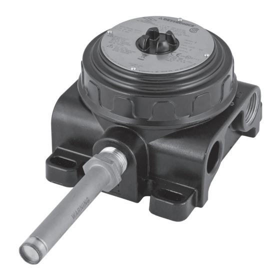
- Page 1 INSTRUCTIONS Risk Area Heat Detector with Explosion-Proof Junction Box Model HD 95-8666...
-
Page 2: Table Of Contents
Calibration Verification ............... 9 SPECIFICATIONS ..................10 DEVICE REPAIR AND RETURN ............10 ORDERING INFORMATION ..............10 Model HD Model Matrix ..............11 APPENDIX A — FM APPROVAL DESCRIPTION ......... 12 APPENDIX B — CSA APPROVAL DESCRIPTION ....... 13 APPENDIX C — ATEX APPROVAL DESCRIPTION ......14 APPENDIX D —... -
Page 3: Description
FEATURES time in the event of a rapidly growing fire. The Model HD Detector senses the surrounding air temperature and • Repeatable - resets itself, nothing to replace, testable actuates its output when the temperature reaches the •... -
Page 4: Applications
DETECTOR ORIENTATION extinguishing devices must be disabled prior to performing system tests or maintenance. The Model HD detector is not position sensitive. The device can be mounted either horizontally or CAUTION vertically depending on the application and installation The detectors are to be installed in places where requirements. -
Page 5: Protection Against Moisture Damage
NOTE according to local codes, at water collection points For optimum performance and maximum service life, care should be taken to protect the Model HD to automatically drain accumulated moisture. It is also from corrosive contaminants in the atmosphere. recommended to install at least one breather, according to local codes, at upper locations to provide ventilation and allow water vapor to escape. -
Page 6: Wiring Procedure
Figures 4 through 7, and Figures 9 through 12. Consult manual for information regarding EOL and SCM the factory if not using shielded cable. resistors. Use Det-Tronics parts or equivalent. In applications where the wiring cable is installed in 2. Resistor leads should be cut to a length of conduit, the conduit must not be used for wiring to approximately 1 1/2 inches, 40 mm. - Page 7 Detector Wiring Figure 2 shows the wiring terminal strips within the junction box. Figure 3 shows the recommended wiring connections for a single detector. Figures 4 thru 7 show single detectors wired in a variety 2560 of typical configurations. Figure 2—Wiring Terminal Identification Figure 8 shows the wiring connections for daisy chained detectors.
- Page 8 HEAT HEAT DETECTOR DETECTOR FIRE FIRE ALARM ALARM PANEL PANEL RESISTOR B2584 Figure 6— Typical Ex d Wiring - 2 Wire with Open Circuit Monitoring RESISTOR B2585 Figure 7— Typical Ex d e Wiring - 4 Wire with Open Circuit Monitoring LAST DETECTOR FIRE...
- Page 9 HEAT HEAT HEAT DETECTOR DETECTOR DETECTOR FIRE ALARM RESISTOR PANEL RESISTOR RESISTOR RESISTOR B2561 Figure 9—Typical Ex d Wiring - 2 Wire with Open and Short Circuit Monitoring HEAT HEAT HEAT DETECTOR DETECTOR DETECTOR FIRE ALARM RESISTOR PANEL RESISTOR RESISTOR RESISTOR B2562 Figure 10—Typical Ex d Wiring - 4 Wire with Open and Short Circuit Monitoring...
-
Page 10: Junction Box Covers
HEAT HEAT HEAT DETECTOR DETECTOR DETECTOR FIRE ALARM PANEL RESISTOR B2564 Figure 12—Typical Ex d e Wiring - 4 Wire with Open Circuit Monitoring JUNCTION BOX COVERS To ease installation and future removal, ensure that the threaded junction box covers are properly lubricated. If additional lubrication is required, use Lubriplate grease (see the “Ordering Information”... -
Page 11: Startup
MAINTENANCE The Model HD detector is a repeatable device with field proven reliability. Properly installed and applied, VISUAL INSPECTION the device offers reliable, economical performance. -
Page 12: Specifications
(13.2) (6.9) ORDERING INFORMATION (9.4) (11.9) When ordering, please specify: 3.46 (1.5) (8.8) Model HD Risk Area Heat Detector with Explosion-Proof Junction Box C2539 Refer to the Model Matrix for details. Figure 14—Dimensions of Heat Detector in Inches (cm) 95-8666... -
Page 13: Model Hd Model Matrix
(3/4” NPT). 101197-004* Stop Plug, 3/4” NPT, Stainless Steel **Note: For use in -20°C to +80°C temperature range only. 101197-005** Stop Plug, M25, Aluminum MODEL HD RISK AREA HEAT DETECTOR MODEL MATRIX MODEL DESCRIPTION Risk Area Heat Detector TYPE SETTING 140°... -
Page 14: Appendix A - Fm Approval Description
Stop Plugs Det-Tronics offers M25 and 3/4 inch NPT stop plugs that have been approved for use with the Model HD. When using any of the stop plugs listed under “Ordering Information,” it is required that each plug be tightened to an installation torque of 35 ft-lb (47.5 N·m) and meet the minimum thread engagement requirements per the applicable standards in order to retain the IP66/IP67 rating. -
Page 15: Appendix B - Csa Approval Description
Stop Plugs Det-Tronics offers M25 and 3/4 inch NPT stop plugs that have been approved for use with the Model HD. When using any of the stop plugs listed under “Ordering Information,” it is required that each plug be tightened to an installation torque of 35 ft-lb (47.5 N·m) and meet the minimum thread engagement requirements per the applicable standards in order to retain the IP66/IP67 rating. -
Page 16: Appendix C - Atex Approval Description
Stop Plugs Det-Tronics offers M25 and 3/4 inch NPT stop plugs that have been approved for use with the Model HD. When using any of the stop plugs listed under “Ordering Information,” it is required that each plug be tightened to an installation torque of 35 ft-lb (47.5 N·m) and meet the minimum thread engagement requirements per the applicable... -
Page 17: Appendix D - Iecex Approval Description
Stop Plugs Det-Tronics offers M25 and 3/4 inch NPT stop plugs that have been approved for use with the Model HD. When using any of the stop plugs listed under “Ordering Information,” it is required that each plug be tightened to an installation torque of 35 ft-lb (47.5 N·m) and meet the minimum thread engagement requirements per the applicable... -
Page 18: Appendix E - Additional Approvals
Stop Plugs Det-Tronics offers M25 and 3/4 inch NPT stop plugs that have been approved for use with the Model HD. When using any of the stop plugs listed under “Ordering Information,” it is required that each plug be tightened to an installation torque of 35 ft-lb (47.5 N·m) and meet the minimum thread engagement requirements per the applicable... - Page 19 Specifications subject to change without notice. All trademarks are the property of their respective owners. © 2020 Detector Electronics Corporation. All rights reserved. Det-Tronics manufacturing system is certified to ISO 9001— Corporate Office Phone: +1 952.941.6665 the world’s most recognized quality management standard.
Need help?
Do you have a question about the HD and is the answer not in the manual?
Questions and answers