
Subscribe to Our Youtube Channel
Related Manuals for Det-Tronics PIRECL


Summary of Contents for Det-Tronics PIRECL
- Page 1 Instructions 95-8526 Infrared Hydrocarbon Gas Detector PointWatch Eclipse ® Model PIRECL 13.1 Rev.10/12 95-8526...
-
Page 2: Table Of Contents
StaRtup . . . . . . . . . . . . . . . . . . . . . . . . . . . . . . . . . 20 piREcl Start-up/commissioning checklists . . . 20 opERation oVERViEW . -
Page 3: Application
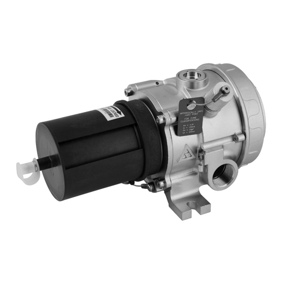
The Pointwatch Eclipse ® Model PIRECL is a diffusion- based, point-type infrared gas detector that provides continuous monitoring of combustible hydrocarbon gas concentrations in the range of 0 to 100% LFL. Three basic configurations are available: •... -
Page 4: Detectable Gases
4-20 mA current loop for connection to analog input the PIRECL wiring compartment. Whenever a third party devices. addressable module is installed, the PIRECL’s Ex e rating and FM Approval are void, and only the Ex d rating is valid. optional relays... -
Page 5: Specifications
Model PIRECL is provided with field-selectable settings for linear measurement of methane, propane, ethylene, RELaY outPutS (optional)— and butane. Model PIRECL is performance certified for (Available on Ex d approved models only, not available detection of methane, propane, ethylene, and butane, on Eagle Premier model). - Page 6 Refer to the “Calibration” section of this Drawing 007283-001 in Appendix J. manual for details. oPtICS PRotECtIon— Routine calibration of the PIRECL after completion of initial The three-layer weather baffle assembly is UV-resistant, commissioning is supported, but not absolutely required. static-dissipating black Polythalimide plastic.
-
Page 7: Important Safety Notes
impoRtant SafEty notES CERtIFICatIon— Refer to the appropriate Appendix for specific information. CaUtIon DIMEnSIonS— See Figure 2. The wiring procedures in this manual are intended to ensure proper functioning of the device under normal conditions. However, because of the SHIPPInG WEIGHt (approximate)— 10.5 pounds (4.8 kg). -
Page 8: Installation
inStallation However, this rule of thumb is subject to change depending upon specific application properties and Before installing the Pointwatch Eclipse, define the requirements. following application details: NOTE For additional information on determining the iDentifiCation of flaMMable Vapor(S) to quantity and placement of gas detectors in be DeteCteD a specific application, refer to the article titled "The Use of Combustible Detectors in Protecting... -
Page 9: 24 Vdc Power Supply Requirements
2. Always determine voltage drops that will occur to communication, the maximum wiring distance is ensure that 24 Vdc is delivered to the Eclipse. 2000 feet. 3. Normally, nothing smaller than 18 AWG (0.75 mm is recommended by Det-Tronics for Eclipse power cabling. 13.1 95-8526... -
Page 10: Optional Relays
Refer to “Alarm Relays” in the Specifications section If it is desired to initiate calibration using the remote of this manual for important information regarding calibrate line, the use of the Det-Tronics Model PIRTB alarm relays. Termination Box is highly recommended for optimum ease of installation and calibration. - Page 11 EARTH GND LUG 24 VDC – 24 VDC + CALIBRATE A2084 24 VDC – Figure 4—terminal Strip Located Inside Wiring Compartment 24 VDC + + 4-20 MA – 4-20 MA RS-485 B RS-485 A RELAY POWER (RED) FAULT WIRING TO OPTIONAL (ORANGE) RELAY BOARD 24 VDC –...
- Page 12 TOTAL LOOP RESISTANCE = 250 OHMS MINIMUM, 600 OHMS MAXIMUM. TOTAL LOOP RESISTANCE = 250 OHMS MINIMUM, 600 OHMS MAXIMUM. DO NOT INSTALL RESISTOR WITHIN PIRECL ENCLOSURE IN EEx e APPLICATIONS. DO NOT INSTALL RESISTOR WITHIN PIRECL ENCLOSURE IN EEx e APPLICATIONS.
- Page 13 HIGH ALARM NOTES: 1 250 OHM RESISTOR REQUIRED IF USING HART PORT COMMUNICATIONS. 2 PIRECL ECLIPSE MUST BE PROGRAMMED TO PIR9400 FAULT MODE FOR PROPER STATUS IDENTIFICATION AT THE U9500H TRANSMITTER. Figure 12—Standard Eclipse Wired to a Model u9500H Infiniti transmitter 13.1...
- Page 14 RS-485 A RELAY POWER FAULT NO USER CONNECTION LOW ALARM HIGH ALARM A2203 B2056 Figure 16—Remote Calibration Switch and LED in optional Figure 15—Wiring the Model PIRECL for Benchtop testing/ Programming using HaRt Protocol Det-tronics PIRtB termination Box 13.1 95-8526...
- Page 15 STANDARD ECLIPSE – 24 VDC – 24 VDC 24 VDC + CALIBRATE MAGNETIC REED SWITCH 24 VDC – FOR REMOTE CALIBRATION 24 VDC + MODEL PIRTB + 4-20 MA – 4-20 MA SPARE RS-485 B RS-485 A TYPICALLY SIGNAL SIGNAL NO CONNECTION RELAY POWER 24 VDC –...
-
Page 16: Description
dEScRiption If a PIRTB Remote Calibration Termination Box is utilized, the HART Communicator can be connected at the PIRTB. internal MagnetiC SwitCh Note that this connection requires removal of the PIRTB cover. An internal magnetic switch is provided for resetting latched alarms and initiating calibration. -
Page 17: Multicolor Led
CloCk table 1—LED Status Indication An hour meter is provided to give a relative indication of time for historical logs. The meter is zeroed at the time of Device Status manufacture and only increments while power is applied. Green Normal operation. HART or MODBUS communication is required to view the Blinking indicates Low Alarm. -
Page 18: Remote Calibration Option
reMote Calibration option 4. Always purge the permanent tubing with clean, dry compressed air prior to and immediately after In most applications, it is recommended to install the calibration to ensure that residual combustible Pointwatch Eclipse where it will contact the vapor of gases are cleared. - Page 19 HAZARDOUS LOCATION NON-HAZARDOUS LOCATION HART COMMUNICATOR PIRECL ISOLATED 4-20 MA PIRTB 24 VDC, CAL 24 VDC + 24 VDC – + 4-20 MA – 4-20 MA CAL GAS HART COMMUNICATOR PIRECL NON-ISOLATED 4-20 MA PIRTB 24 VDC + 24 VDC –...
-
Page 20: Operation
opERation 4-20 Ma CUrrent loop oUtpUt Eclipse provides an isolated, linear current loop output faCtory DefaUlt SettingS that is proportional to the detected gas level. Fault and The Pointwatch Eclipse is shipped from the factory pre- calibration status are also indicated by this output. calibrated and set for the customer’s choice of 0-100% LFL methane, propane, ethylene, or butane. -
Page 21: Fault Indication
Mode warm-up, general fault, calibration, and blocked optics. This mode is provided for compatibility with existing Det-Tronics PointWatch gas detectors. The fault and calibration levels are identical to existing PIR9400 units, which makes the Eclipse compatible with the U9500 Infiniti Transmitter. -
Page 22: Startup
StaRtup Mechanical Checklist • PIRECL detector is mounted to a solid surface not When the Eclipse is installed and wired as described in prone to high vibration, shock, traumatic impact or the “Installation” section, it is ready for commissioning. other undesirable condition. -
Page 23: Calibration
The following Normal Calibration guidelines always situation is easily corrected by using the Eclipse apply: Calibration Bag (P/N 006672-002), available from Det-Tronics. A. The Eclipse is factory set for detection of methane, propane, ethylene, or butane. If the NOTE gas setting is changed (using HART, MODBUS... -
Page 24: Calibration Initiation
Calibration initiation DetaileD Calibration proCeDUre USing MagnetiC SwitCh Eclipse calibration may be initiated by any of the following means: Refer to Tables 4 and 5 for a quick summary of the standard calibration sequence. • The onboard magnetic calibration switch •... -
Page 25: Time Out
table 4—Quick Reference Guide for normal Calibration Procedure using Magnetic Switch Description indicating leD Current output operator action (on-board/pirtb) (default setting) Normal-ready to calibrate steady green/off 4 mA Purge with clean air if required Initiate Calibration steady red/on-steady 1 mA Apply Magnet for 2 seconds min. -
Page 26: Maintenance
Cleaning of the Eclipse optical surfaces is normally NOTE required only if an optical fault is indicated. Refer to the Model PIRECL Safety Manual (number 95-8630) for specific requirements Thoroughly douse the mirror and window using a liberal and recommendations applicable to the proper... -
Page 27: Troubleshooting
tRoublEShooting dEvicE REpaiR and REtuRn A Fault status is indicated by a yellow LED and also by The Pointwatch Eclipse IR Hydrocarbon Gas Detector is the 4-20 mA outout. Refer to Table 6 to identify the fault not designed to be repaired in the field. If a problem type using the 4-20 mA output. -
Page 28: Ordering Information
Spare partS Weather Baffle with Inlet Nozzle, 007165-002 pointwatCh eClipSe DeteCtor with Hydrophobic Filter When ordering, please refer to the PIRECL Model Weather Baffle with Inlet Nozzle, 007165-001 Matrix. without Hydrophobic Filter Weather Baffle w 1/16” NPT cal... - Page 29 MoDel Matrix MoDel DeSCription pireCl Point Infrared Eclipse Gas Detector type threaD type 3/4” nPt type oUtpUt & MeaSUreMent optionS 4-20 ma with HaRt protocol & RS-485: 0-100% LFL Full Scale Range Eagle Quantum Premier (EQP): 0-100% LFL Full Scale Range...
- Page 30 Performance verified for 0 to 100% LFL Butane-in-air atmospheres per FM 6310/6320 and ANSI 12.13.01. NOTES Approval of the Model PIRECL does not include or imply approval of the apparatus to which the detector may be connected and which processes the electronic signal for eventual end use. In order to maintain an approved system, the apparatus to which the detector is connected must also be approved.
- Page 31 AccuRAcy— ±3% LFL from 0 to 50% LFL, ±5% LFL from 51 to 100% LFL (at room ambient temperature, +23°C). NOTE Product operates properly with 5 watt walkie talkie keyed at 1 meter. other GAses The Pointwatch Eclipse ® is provided with field-selectable “standard gas” signal processing program settings for linear measurement of methane, propane, ethylene, and butane gases.
- Page 32 Performance verified for 0 to 100% LFL Butane-in-air atmospheres per C22.2 #152. NOTES Approval of the Model PIRECL does not include or imply approval of the apparatus to which the detector may be connected and which processes the electronic signal for eventual end use. In order to maintain an approved system, the apparatus to which the detector is connected must also be approved.
- Page 33 AccuRAcy— ±3% LFL from 0 to 50% LFL, ±5% LFL from 51 to 100% LFL (at room ambient temperature, +23°C). other GAses The Pointwatch Eclipse ® is provided with field-selectable “standard gas” signal processing program settings for linear measurement of methane, propane, ethylene, and butane gases. This means that the Eclipse is capable of providing an analog signal output that is directly proportional to the % LFL concentration for these gases, provided the proper gas setting has been selected, and the Eclipse has been calibrated with the proper calibration gas type.
-
Page 34: Appendix C - Atex Approval Description
EC-Type Examination Certificate in the following configurations: 1. PIRECL Infrared Gas Detector (LON Model) tested in combination with the EQP System Controller Model EQ3XXX. 2. PIRECL Infrared Gas Detector tested in combination with the Model PIRTB, Termination Box. - Page 35 AteX special conditions for safe Use (‘X’): • The Infrared Gas Detector model PIRECL shall be installed in places where there is a low risk of mechanical damage. • The field wiring terminal connections are certified for a single wire in size from 0.2 to 2.5 mm , (or two conductors with same cross section 0.2 to 0.75 mm ).The screws must be tightened down with a torque 0.4 to 0.5 Nm. • The metal housing of the model PIRECL Infrared Hydrocarbon Gas Detector must be electrically connected to earth ground. • The intrinsically safe output on the HART Communicator Port is internally connected to earth ground.
- Page 36 RESPONSE TIME (Average in Seconds, with Weather Protection Baffle Installed, and 100% LFL Applied)— Baffle Without Hydrophobic Filter Methane With Hydrophobic Filter Without Hydrophobic Filter Propane With Hydrophobic Filter Without Hydrophobic Filter Ethylene With Hydrophobic Filter 10.0 Without Hydrophobic Filter Butane With Hydrophobic Filter Average of three consecutive trials, with the minimum and maximum response times no greater...
-
Page 37: Appendix D - Iecex Approval Description
ApprovAl Description The following items, functions and options describe the IECEx approval. ApprovAl PointWatch Eclipse ® Infrared Hydrocarbon Gas Detector, Model PIRECL Series. IECEx ULD 04.0002X Ex de IIC T4-T5 Gb -- OR -- Ex de [ib] IIC T4-T5 Gb (with HART communication port) T5 (Tamb –50°C to +40°C) -
Page 38: Appendix E - Other Approvals
Relevant tests according to “Standard for Certification No. 2.4”. Certificate No. MED-B-5866. Model PIRECL IR Hydrocarbon Gas Detector and PIRTB Termination Box are found to comply with the requirements in the following Regulations/Standards: Annex A.1, item No. A.1/3.54 and Annex B, Module B in the Directive. SOLAS 74 as amended, Regulation II-2/4 &... - Page 39 inMetro CEPEL 02.0078X Ex d [ib] IIC T4-T5 Gb IP66/67 T5 (T amb –55°C to +40°C) T4 (T amb –55°C to +75°C) ––OR–– Ex d e [ib] IIC T4-T5 Gb IP66/67 T5 (T amb –50°C to +40°C) T4 (T amb –50°C to +75°C) Note: All cable entry devices or blanking elements shall be Brazil certified in the type of explosion protection, flameproof enclosure ‘d’, suitable for the conditions of use and correctly installed, with an ingress protection rating of IP66/IP67.
-
Page 40: Appendix F - Hart Communication
HART communication with the PIRECL detector will be established, but the Communicator will not recognize the PIRECL as a gas detector. Generic HART communication will not provide access to the PIRECL DDL menu and important set-up, diagnostics or operation functions, including gas type selection. - Page 41 eclipse hArt MenU strUctUre This section displays the menu trees for the Pointwatch Eclipse. The Menu tree shows the primary commands and options available when using menu selections. 1 Self Test 1 Gas xxxxxxxx 2 Response Test 2 Conc 0.0% LEL 1 Process Variables 3 Reset 3 AO...
- Page 42 Communicator does not measure loop resistance. Any external ohmmeter is required. coMMonlY UseD hArt coMMAnDs The most commonly used HART commands for the PIRECL are: 1. Performing basic setup functions such as: • Assigning a tag number to the detector • Assigning unit of measure (%LEL, PPM, % Vol)
- Page 43 1. Inspect the Root menu to confirm that the gas type selected is proper for the gas hazard to be detected. The PIRECL is shipped from the factory calibrated and set for detection of methane, propane, ethylene, or butane. If a different gas type is desired, then change the setting using the detailed setup programming option, and perform a field calibration using the same gas type as is selected.
- Page 44 Device setUp sUBMenU The Device Setup menu accesses every configurable parameter of the connected device. 1 Process Variables The first accessible setup parameters include: 2 Diag/Service 1 process variables Selecting this menu item will list all process variables and their values. 3 Basic Setup These process variables are continuously updated, and include: Gas xxxxx (gas type being detected).
- Page 45 DiAGnostics/service MenU 1 Test Device The specific diagnostic and/or service functions available are: 2 Loop Test 1 test Device 1 Self-test. Internal tests are performed and any problems are reported in xmtr flt 1 and xmtr flt 2. 3 Calibration 2 Response Test.
- Page 46 5 history This menu option shows extensive historical information about the detector. Data available includes: 1 Running hrs xxxx (the number of hours the unit has been powered). 2 Max temperatures (the maximum temperatures recorded in the device). See max temperature submenu below. 3 Min temperatures (the minimum temperatures recorded in the device).
- Page 47 BAsic setUp sUBMenU 1 Tag The tag number identifies a specific device. Changing units affects the engineering units that are displayed. Re-ranging changes the analog output scaling. 2 PV Unit xxxxx 1 tag Press to access the Tag number menu. Enter the device tag number as desired. 3 Range Values 2 pv Unit 4 Device Information...
- Page 48 DetAileD setUp MenU 1 Sensor Information 1 sensor information This menu provides detailed information on the internal detector operations. Submenu 2 Gas Type xxxxx options include: 1 PV USL xxxx. The upper sensor limit value defines the maximum usable value for the upper range of the sensor. 3 Output Condition 2 Active xxxx (output value of the active sensor).
- Page 49 3 output condition Select and configure the output signal options for the Eclipse detector. Submenu options: 1 Config Gas Alarms. Submenu options inlcude: 1 High Alarm Level. The high alarm level cannot be set higher than 60% LEL or lower than the low alarm level.
- Page 50 4 Device information Press to access device information submenu: 1 Tag xxxx 2 Date 6/30/2000 3 Descriptor (text associated with the field device that can be used by the operator in any way). 4 Message (text associated with the field device that can be used by the operator in any way). 5 Model: Eclipse 6 Write protect xx.
-
Page 51: Appendix G - Modbus Communication
SLAVE #1 MASTER A2340 ECLIPSE SLAVE #2 ECLIPSE SLAVE #N Individual Eclipse units are wired as shown below. Note the inclusion of the end-of-line termination resistor. PIRECL – –24 VDC 24 VDC +24 VDC POWER SUPPLY CALIBRATE –24 VDC +24 VDC + 4-20 MA –... - Page 52 hArDWAre lAYer RS-485 is used for the hardware interface layer. The output drivers are capable of driving at least 32 devices. The device RS-485 output is tri-stated until a command address matches the programmed address. Default serial settings are MODBUS protocol, address 1, 9600 baud, 1 stop bit, and no parity. MoDBUs FUnction coDes supported Modbus Functions Function number...
- Page 53 Device configuration: (read/Write) This area of memory holds field adjustable parameters for the device. The Hart configuration changed bit will be set on writes to this area. eclipse Device configuration Description Address value Modbus Polling Address 40101 1..247 Baud Rate Code 40102 See Codes Parity Code 40103 See Codes Gas Type 40104 See Codes Calibration Gas Type 40105 See Codes Calibration Method 40106...
- Page 54 Device status (read only) This area of memory holds real time status information. eclipse status information Description Address value General Status Bits 40201 Bit Values (See below) Fault Status Bits 40202 Bit Values (See below) Gas Level in LEL 40203 Float LSW 40204 Float MSW...
- Page 55 eclipse status information (continued) Description Address value Min Temperature 40239 Float LSW 40240 Float MSW Min Temp Hour 40241 Unsigned Long LSW 40242 Unsigned Long MSW Min Temp (Since Reset) 40243 Float LSW 40244 Float MSW Min Temp Hour (Since Reset) 40245 Unsigned Long LSW 40246...
- Page 56 Fault status Word These bits are used to signal the active faults of the device. name Calibration Fault Dirty Optics Open Lamp Cal Active at start EE Error 1 EE Error 2 Ref ADC Saturated Active ADC Saturated Bad 24 volts Bad 12 volts Bad 5 volts Zero Drift...
- Page 57 command Word 1 Description Start Calibration Abort Calibration Warm up Mode Low Alarm Active High Alarm Active Output Current Fixed Modbus Write Protect Calibration Input Active Magnetic Switch Active Hart Initiated Self Test Reserved Response Test Active Manual Self Test Active End Response Test Reserved Start Manual Self Test...
- Page 58 vAlUe coDes Baud rate code Description code 1200 2400 4800 9600 (Default) 19200 parity code Description code None (Default) Even Gas type Description code Methane Ethane Propane Ethylene Propylene Butane Reserved Reserved Reserved Special 95-8526 13.1...
- Page 59 calibration Gas type Description code Same as Measured Methane Propane calibration Method Description code Standard Cuvette Analog Fault code Description code Eclipse PIR 9400 User Defined calibration step Description code Waiting to Start Waiting for Zero Waiting for Signal Waiting for Gas Waiting for Span Waiting for End Calibration Terminated...
- Page 60 Alarm latch configuration NOTE Refer to “Alarm Relays” in the Specifications section of this manual for important information regarding alarm relays. Description code Non-Latching Latching event log iD codes Description code Empty Blocked Beam Warm-up Zero Drift Low Alarm High Alarm calibration log iD codes Description code...
- Page 61 QUAntUM preMier coMpAtiBle eclipse instAllAtion AnD WirinG The Eagle Quantum Premier (EQP) version of the Model PIRECL PointWatch Eclipse uses the identical installation procedure, device location guidelines, and power supply requirements as described in the “Installation” section of this manual.
- Page 62 RS-485 communication is not available with EQP PIRECL. cAliBrAtion roUtine The calibration procedure for the EQP PIRECL (normal and zero calibration) is identical to all other PIRECL versions. NotE For complete information regarding installation, configuration or operation of the Eagle Quantum Premier system, refer to form 95-8533 (Eagle Quantum Premier hardware manual) or form 95-8560 (Safety System Software manual).
- Page 63 Addresses Each PIRECL IR gas detector on the EQP LON must be assigned a unique address. Addresses 1 to 4 are reserved for the EQP controller. Valid addresses for field devices including PIRECL gas detectors are from 5 to 250.
- Page 64 ImpoRtANt The PIRECL sets the LON address only when power is applied to the device. Therefore, it is important to set the switches before applying power. If an address is ever changed, system power must be cycled before the new address will take effect.
- Page 65 LON devices on the Address Identification Chart before disassembling and programming the PIRECL gas detectors. Removal of four stainless steel flange bolts and the front electronic module of the PIRECL IR gas detector from the bulkhead is required in order to gain access to the network address DIP switch. Tools required for this procedure include a 4mm hex wrench and a torque wrench capable of accurately measuring 40 inch-pounds.
- Page 66 SINGLE SOLENOID DUAL SOLENOIDS CH 1 CH 2 CH 3 CH 4 CH 5 CH 6 CH 7 CH 8 RELAY 2 RELAY 3 RELAY 4 RELAY 1 DIGITAL INPUTS RELAY 5 RELAY 6 RELAY 7 RELAY 8 95-8526 13.1...
-
Page 67: Appendix I - Warranty
Appendix i WArrAntY Detector Electronics Corporation products are manufactured from high quality components and the completed device is rigorously inspected and tested before shipment; however, any electronic device is subject to failure beyond the control of the manufacturer. To ensure system reliability, it is important for the user to maintain the system as recommended by the instruction manuals and to determine the frequency of functional checking of the system required for each specific installation. The more frequent the checking, the greater the system reliability. For the highest reliability, a completely redundant system is necessary. -
Page 68: Appendix J - Control Drawing
Appendix J control DrAWinG 13.1 95-8526... - Page 69 Safety System Det-Tronics, the DET-TRONICS logo, Eagle Quantum Premier, FlexVu and Eclipse are registered trademarks or trademarks of Detector Electronics Corporation in the United States, other countries, or both. Other company, product, or service names may be trademarks or service marks of others.
Need help?
Do you have a question about the PIRECL and is the answer not in the manual?
Questions and answers