
Related Manuals for Det-Tronics Protect IR X3302


Summary of Contents for Det-Tronics Protect IR X3302
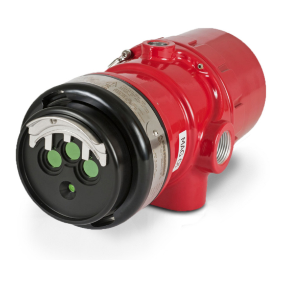
- Page 1 Instructions 95-8576 Protect•IR ® Multispectrum IR Flame Detector X3302 Rev: 4/09 95-8576...
-
Page 2: Table Of Contents
Table Of Contents Description . . . . . . . . . . . . . . . . . . . . . . . . . . . . . . . . . . . . . . . . . . . . 1 outputs . -
Page 3: Description
INSTRUCTIONS ® Protect•IR Multispectrum IR Flame Detector X3302 Important Be sure to read and understand the entire instruction manual before installing or operating the flame detection system. Any deviation from the recommendations in this manual may impair system performance and compromise safety. attEntIon The X3302 includes the Automatic Optical Integrity ( o i ®) feature —... -
Page 4: Outputs
LON/SLC Output The EQP model is designed for use exclusively with The Fire Alarm relay has redundant terminals and the Det-Tronics Eagle Quantum Premier system. The normally open / normally closed contacts, normally detector communicates with the system controller over... -
Page 5: Communication
NOTE respond. Refer to the Appendix for FM verification of Det-Tronics’ Optical Integrity o i function. welding Arc welding should not be performed within 20 feet of COMMUNICATION the detector. Gas welding mandates system bypass, The X3302 is furnished with an RS-485 interface for since the gas torch is an actual fire. -
Page 6: Important Safety Notes
INSTallaTION EMI/RFI Interference The X3302 is resistant to interference by EMI and RFI, DETECTOR pOSITIONING and is EMC Directive compliant. It will not respond to a 5 Detectors should be positioned to provide the best watt walkie-talkie at distances greater than 1 foot. Do not unobstructed view of the area to be protected. -
Page 7: Detector Orientation
pROTECTION AGAINST MOISTURE DAMAGE It is important to take proper precautions during installation to ensure that moisture will not come in contact with the CENTER AXIS electrical connections or components of the system. The OF DETECTOR FIELD OF VIEW integrity of the system regarding moisture protection must be maintained for proper operation and is the responsibility of the installer. -
Page 8: Wiring Procedure
wIRING pROCEDURE Detector Mounting Install the swivel mounting bracket assembly on the wall. wire Size and Type The installation surface should be free of vibration and The system should be wired according to local codes. suitable to receive 1/4 inch (M6) screws with a length of The wire size selected should be based on the number at least 1 inch (25 mm), and have sufficient capacity to of detectors connected, the supply voltage and the cable... - Page 9 Check all field wiring to be sure that the proper connections have been made. Important Do not test any wiring connected to the detector with a meg-ohmmeter. Disconnect wiring at the detector before checking system wiring for continuity. Make the final sighting adjustments and ensure that the mounting bracket hardware is tight.
- Page 10 X3302 DETECTOR FIRE ALARM PANEL 4-20 mA – 4-20 mA + SPARE 4-20 mA + REF 4-20 mA – REF SPARE COM FIRE 2 COM AUX COM FIRE N.O. FIRE 2 N.O. AUX N.O. FIRE E.O.L. DEVICE 4 N.C. FIRE 2 N.C.
- Page 11 X3302 IR DETECTOR X3302 IR DETECTOR 4-20 mA + 4-20 mA – 4-20 mA + 4-20 mA – AT 24 VDC AT 24 VDC 4-20 mA – REF 4-20 mA + REF – – 4 TO 20 mA 4 TO 20 mA 24 VDC 24 VDC –...
- Page 12 EQp Model Check all field wiring to be sure that the proper connections have been made. Connect external wires to the appropriate terminals inside the device junction box. (See Figure 13 for Replace the device cover. terminal identification.) Make the final sighting adjustments and ensure that Connect the shield of the power cable to “earth the mounting bracket hardware is tight.
- Page 13 CH 1 CH 2 CH 3 CH 4 CH 5 CH 6 CH 7 CH 8 RELAY 2 RELAY 3 RELAY 4 RELAY 1 DIGITAL INPUTS RELAY 5 RELAY 6 RELAY 7 RELAY 8 95-8576...
-
Page 14: Setting Device Network Addresses (Eqp Model Only)
ADDRESS SWITCHES SENSOR MODULE REMOVED FROM HOUSING A2191 Figure 15—Location of Address Switches SETTING DEVICE NETwORk ADDRESSES (EQp Model Only) The address number is binary encoded with each switch having a specific binary value with switch 1 Overview of Network Addresses being the LSB (Least Significant Bit). -
Page 15: Startup Procedure
Verify that all detectors in the system are properly Turn off the input power to the detector and check all aimed at the area to be protected. (The Det-Tronics wiring for continuity. Important: Disconnect wiring Q1201C Laser Aimer is recommended for this at the detector before checking system wiring for purpose.) -
Page 16: Maintenance
If the o i plate is removed, be sure to install the original o i plate. O i plates are not To clean the windows and o i plate, use Det-Tronics interchangeable and should not be mixed with window cleaner (part number 001680-001) and a soft o i plates from other detectors. -
Page 17: Features
fEaTURES For HART model, refer to Addendum number 95-8613. POWER UP TIME— • Unequaled false alarm rejection. Fault indication clears after 0.5 second; device is ready • Responds to a fire in the presence of modulated to indicate an alarm condition after 30 seconds. blackbody radiation (i.e. - Page 18 Conforms with: Low Voltage Directive (73/23/EEC). WIRING— Field wiring screw terminals are UL/CSA rated for up to Electromagnetic Compatibility Directive 14 AWG wire, and are DIN/VDE rated for 2.5 mm wire. (89/336/EEC). Screw terminal required torque range is 3.5–4.4 in.-lbs. Explosive Atmosphere Directive (0.4-0.5 N·m).
-
Page 19: Replacement Parts
REPlaCEmENT PaRTS ORDERING INfORmaTION The detector is not designed to be repaired in the field. When ordering, please specify: If a problem should develop, refer to the Troubleshooting X3302 IR Flame Detector section. If it is determined that the problem is caused by Refer to the X3302 Model Matrix for details an electronic defect, the device must be returned to the factory for repair. - Page 20 X3302 MODEL MATRIX MODEL DESCRIpTION X3302 Multispectrum IR Flame Detector TYpE MATERIAL Aluminum Stainless Steel (316) TYpE ThREAD TYpE 4 PORT, METRIC M25 4 PORT, 3/4" NPT TYpE OUTpUTS Relay and 4-20 mA Eagle Quantum Premier Relay and Pulse Addressable Module Only (Third Party Type) Relay, 4-20 mA and HART TYpE AppROVAL AGENCY...
-
Page 21: Appendix
aPPENDIX FM Approvals Description and performance Report THE FOLLOWING ITEMS, FUNCTIONS AND OPTIONS DESCRIBE THE FM APPROVAL: • Explosion-proof for Class I, Div. 1, Groups B, C and D Hazardous (Classified) Locations per FM 3615. • Dust-ignition proof for Class II/III, Div. 1, Groups E, F and G Hazardous (Classified) Locations per FM 3615. •... - Page 22 FM Approvals Description and performance Report – Continued RESpONSE ChARACTERISTICS: Very high Sensitivity Distance Avg. horiz. Response Fuel Size / Flow Rate feet (m) Time (seconds) Hydrogen 24inch plume/100 SLPM* 100 (30.5) Methanol 1 x 1 foot 70 (21.3) Standard Liters Per Minute (Standard conditions defined as +25°C and 14.696 PSIA) FIELD OF VIEw: Very high Sensitivity Size/...
- Page 23 FM Approvals Description and performance Report – Continued RESpONSE ChARACTERISTICS IN ThE pRESENCE OF FALSE ALARM SOURCES: Very high Sensitivity Unmodulated Source False Alarm Souce Distance Distance Average Response Time Fire Source Unmodulated feet (m) feet (m) (seconds) Two 34 w fluorescent lamps 5 (1.5) 100 SLPM 100 (30.5)
- Page 24 FM Approvals Description and performance Report – Continued hIGh RESOLUTION FIELD OF VIEw 0° 0° 15° 15° 15° 15° 100 ft 70 ft 30° 30° 90 ft 30° 30° 60 ft 80 ft 45° 45° 45° 45° 50 ft 70 ft 60 ft 40 ft 50 ft...
- Page 25 E-Mail: info@dsf-gmbh.de Det-Tronics, the DET-TRONICS logo, Protect•IR, and Automatic Optical Integrity (o i ) are registered trademarks or trademarks of Detector Electronics Corporation in the United States, other countries, or both. Other company, product, or service names may be trademarks or service marks of others.
Need help?
Do you have a question about the Protect IR X3302 and is the answer not in the manual?
Questions and answers