Sign In
Upload
Download
Table of Contents
Contents
Add to my manuals
Delete from my manuals
Share
URL of this page:
HTML Link:
Bookmark this page
Add
Manual will be automatically added to "My Manuals"
Print this page
×
Bookmark added
×
Added to my manuals
Manuals
Brands
Det-Tronics Manuals
Security Sensors
R7404
Instructions manual
Det-Tronics R7404 Instructions Manual
Ultraviolet flame detection system, controller, detector
Hide thumbs
1
Table Of Contents
2
3
4
5
6
7
8
9
10
11
12
13
14
15
16
17
18
19
20
21
22
23
24
25
26
27
28
29
30
page
of
30
Go
/
30
Contents
Table of Contents
Troubleshooting
Bookmarks
Table of Contents
Table of Contents
System Application
Features
General Application Information
System Description
Detector
Controller
Specifications
Detector Sensitivity
System Sensitivity Considerations
Installation
Wiring Requirements
Detector Positioning and Density
Mounting the Detector
Controller
Typical System Applications
Startup Procedure
Checkout Procedure
Manual O I Check
Detector Count Test
Manual Check in Normal Mode
Maintenance
Troubleshooting
Device Repair and Return
Ordering Information
Options
Recommended Spare Parts
Advertisement
Quick Links
1
System Application
2
Detector
3
Specifications
4
Maintenance
5
Troubleshooting
Download this manual
Instructions
95-8242
Ultraviolet Flame Detection System
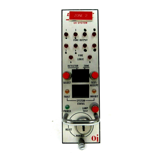
R7404 Controller
C7050 Detector
7.1
Rev: 11/10
95-8242
Table of
Contents
Previous
Page
Next
Page
1
2
3
4
5
Advertisement
Table of Contents
Need help?
Do you have a question about the R7404 and is the answer not in the manual?
Ask a question
Questions and answers
Related Manuals for Det-Tronics R7404
Security Sensors Det-Tronics X Series Instructions Manual
Enhanced flame inspector software for use with det-tronics flame detectors (20 pages)
Security Sensors Det-Tronics C7050 Instructions Manual
Ultraviolet flame detection system, controller, detector (30 pages)
Security Sensors Det-Tronics OPECL Instructions Manual
Infrared hydrocarbon gas detector open path eclipse (24 pages)
Security Sensors Det-Tronics Protect IR X3302 Instructions Manual
Multispectrum ir flame detecto (25 pages)
Security Sensors Det-Tronics PIRECL Instructions Manual
Infrared hydrocarbon gas detector pointwatch eclipse (69 pages)
Security Sensors Det-Tronics LS2000 Instructions Manual
Line of sight infrared hydrocarbon gas detector (46 pages)
Security Sensors Det-Tronics X5200 Instructions Manual
Uvir flame detector (34 pages)
Security Sensors Det-Tronics X3301 Instructions Manual
Protect-ir multispectrum ir flame detector with pulse output (27 pages)
Security Sensors Det-Tronics X3301 Instructions Manual
Multispectrum ir flame detector (43 pages)
Security Sensors Det-Tronics Protect-IR X3301 Instructions Manual
Multispectrum ir flame detector (28 pages)
Security Sensors Det-Tronics X3300 Instructions Manual
Protect-ir multispectrum ir flame detector with pulse output (27 pages)
Security Sensors Det-Tronics Automatic Eagle Quantum EQ2200UV Manual
Uv flame detector (8 pages)
Security Sensors Det-Tronics X3301 Instructions Manual
Multispectrum ir flame detector with pulse output (39 pages)
Security Sensors Det-Tronics Open Path Eclipse Instructions Manual
Infrared hydrocarbon gas detector (49 pages)
Security Sensors Det-Tronics FlexSonic Instructions Manual
Acoustic detector, sensor, transmitter (38 pages)
Security Sensors Det-Tronics Eagle Quantum EQ2200UVHT Installation Manual
For use with c7050b continuous duty high temperature uv flame detector (8 pages)
This manual is also suitable for:
C7050
Table of Contents
Save PDF
Print
Rename the bookmark
Delete bookmark?
Delete from my manuals?
Login
Sign In
OR
Sign in with Facebook
Sign in with Google
Upload manual
Upload from disk
Upload from URL


Need help?
Do you have a question about the R7404 and is the answer not in the manual?
Questions and answers