Table of Contents
Advertisement
SEMS Portal App
LinkedIn
Offical Website
GOODWE (Germany)
Fürstenrieder Str. 279a 81377 München, Germany
T: +49 8974120210 +49 421 83570-170 (service)
sales.de@goodwe.com
service.de@goodwe.com
GOODWE (Netherlands)
Franciscusdreef 42C, 3565AC Utrecht, the Netherlands
T: +31 (0) 30 737 1140
sales@goodwe.com
service.nl@goodwe.com
GOODWE (India)
1202, G-Square Business Park, Sector 30A, Opp. Sanpada
Railway Stn., Vashi, Navi Mumbai- 400703
T: +91 (0) 2249746788
sales@goodwe.com / service.in@goodwe.com
GOODWE (Turbutton)
Adalet Mah. Megapol Tower K: 9 No: 110 Bayraklı - Izmir
T: +90 (232) 935 68 18
info@goodwe.com.tr
service@goodwe.com.tr
GOODWE (Mexico)
Oswaldo Sanchez Norte 3615, Col. Hidalgo, Monterrey,
Nuevo Leon, Mexico, C.P. 64290
T: +52 1 81 2871 2871
sales@goodwe.com / soporte.latam@goodwe.com
Note: The information above is subject to change without prior notice, for details refer to
www.goodwe.com
GOODWE (China)
No. 90 Zijin Rd., New District, Suzhou, 215011, China
T: +86 (0) 512 6958 2201
sales@goodwe.com (sales)
service@goodwe.com (service)
GOODWE (Brazil)
Rua Abelardo 45, Recife/PE, 52050-310
T: +55 81 991239286
sergio@goodwe.com
servico.br@goodwe.com
GOODWE (UK)
6 Dunhams Court, Dunhams Lane, Letchworth
Garden City, SG6 1WB UK
T:+ 44 (0) 333 358 3184
enquiries@goodwe.com.uk / service@goodwe.com.uk
GOODWE (Italy)
Via Cesare Braico 61, 72100 Brindisi, Italy
T: +39 338 879 38 81; +39 831 162 35 52
valter.pische@goodwe.com (sales)
operazioni@topsenergy.com; goodwe@arsimp.it (service)
GOODWE (Australia)
Level 14, 380 St. Kilda Road, Melbourne,
Victoria, 3004, Australia
T: +61 (0) 3 9918 3905
sales@goodwe.com / service.au@goodwe.com
GOODWE (Korea)
8F Invest Korea Plaza, 7 Heoleung-ro
Seocho-gu Seoul Korea (06792)
T: 82 (2) 3497 1066
sales@goodwe.com / Larry.Kim@goodwe.com
NS.DNS SERIES USER MANUAL
SOLAR INVERTER
Version 1.0.1
Advertisement
Table of Contents

Related Manuals for Goodwe NS Series


Summary of Contents for Goodwe NS Series
- Page 1 T: +31 (0) 30 737 1140 Garden City, SG6 1WB UK sales@goodwe.com T:+ 44 (0) 333 358 3184 service.nl@goodwe.com enquiries@goodwe.com.uk / service@goodwe.com.uk GOODWE (India) GOODWE (Italy) 1202, G-Square Business Park, Sector 30A, Opp. Sanpada Via Cesare Braico 61, 72100 Brindisi, Italy Railway Stn., Vashi, Navi Mumbai- 400703...
-
Page 2: Table Of Contents
1 Symbols ..........................2 Safety Measures & Warning ............... 3 Product Introduction ..................3.1 Inverter Overview ........................04 3.2 Package ............................05 4 Installation ........................4.1 Mounting Instructions ....................... 06 4.2 Equipment Installation ......................06 4.3 Electrical Connection ........................ 08 4.4 Communication Connection .................... -
Page 3: Symbols
The NS/DNS series inverter of Jiangsu GOODWE Power Supply Technology Co, Ltd. (hereinafter Failure to observe a warning indicated in this manual may result in referred to as GOODWE) strictly conforms to related safety rules in design and test. Safety regula- injury. -
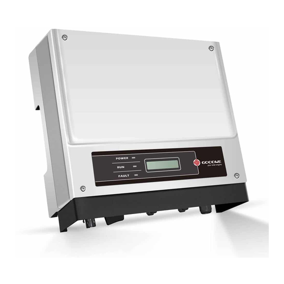
Page 4: Product Introduction
/ holes. 1. PV Input Terminal 2. DC Switch (Optional) To our inverter product, GOODWE provides standard manufacture warranty which comes with the 3. RS485/USB Port product and prepaid warranty extension solution to our customer. You can find the details about 4. -
Page 5: Package
• The location must be well ventilated and sheltered from direct sunlight. • Install inverter vertically or with a backward tilt within 15 degrees. No lateral tilt is allowed. The NS series 1 pair; area of the connectors should point downwards. -
Page 6: Electrical Connection
Mounting procedure for DNS 300mm Expansion Pipe 195mm Wall-Mounting Bracket Upward -------------- 300mm 200mm 200mm 300mm Downward ---------- 500mm Front ----------------- 300mm Both sides ---------- 200mm 115mm 500mm Self-tapping Screws 130mm 4.2.2 Mounting Procedure 1. Use the wall-mount bracket as a template and drill holes with 10mm in diameter and 80 mm in depth on the wall. - Page 7 Installation instruction of VACONN series 4.3.2 AC Circuit Breaker And Residual Current Protection Device In order to ensure that the inverter can be safe and reliable to disconnect from the power grid Fasten screw cap clockwise 10mm please install an independent two pole circuit breaker to protect the inverter. The inverter can exclude the possibility of DC residual currents to 6mA in the system, where an external RCD is required in addition to the build-in RCMU, type A can be used, type B or type A must be used to avoid tripping.
- Page 8 Step 3 Fix the earth wire on the machine. In order to improve the corrosion resistance of the terminal, it is recommended to apply AMPHENOL SERIES QC4.10 SERIES silica gel on the earth terminal for corrosion protection after the grounding cable assembly is completed.
-
Page 9: Communication Connection
4.4 Communication Connection Please follow the steps below to complete RS485 communication connection. 4.4.1 USB Connection Step 1: Screw this plate off from inverter. USB interface is only used for after-sales service team to repair inverter, Not allowed for any other purposes. - Page 10 After configuration, please borrow the monitoring portal website to create PV station. Step 2-1 For DRED: 4.4.4 Export Power Limit Connection Diagram Put the cable through the connector and The methods of connecting the Power Limiting device CT is shown below. connect to the terminal.
-
Page 11: System Operation
5.1.1 Indicator Lights 3. CT is directional. Please make sure CT+ is properly connected to white & black wire and CT- to NS series. black wire. Please make sure the limit buckle is connected to the output live wire (L) of inverter. -
Page 12: User Interface And System Configuration
5.2 User Interface And Syetem Configuration ing, fault occurrence or button operation. 5.2.6 Menu Introduction 5.2.1 Operation Method • When the PV panel is feeding power to the inverter, the LCD displays the first-level menu. There are two modes of button operation: Short press the button and long press the button. •... - Page 13 • Set language First Level Menu Second Level Menu Normal Long Press 50Hz Grid Default Short press the button to enter the "Set Language" menu. Long press the button to enter the Pac=2595.5W Short Press second level menu. Short press the button to browse the languages available. E-Today=15.2KWh Long Press Lock...
-
Page 14: Error Message
default is OFF) and the power limiting setting (the default is 2% rated power): Long press the the button to check the result. button to enter password input menu. The initial display "1111" is the default password. Short First Level Menu Second Level Menu First Level Menu press the button to increase the number in current location and long press to move to the cursor... -
Page 15: Wi-Fi Reset & Wi-Fi Reload
6 Troubleshooting 5.4 Wi-Fi Reset & Wi-Fi Reload These functions are only available for Wi-Fi model inverters. In most situations, the inverter requires very little maintenance. However, if the inverter is not working properly, please try the following troubleshooting solutions: Wi-Fi reload function is used to change the Wi-Fi configuration to default value. -
Page 16: Technical Parameters
7 Technical Parameters Type of fault Troubleshooting Relay-Check Failure Technical Data GW1000-NS GW1500-NS GW2000-NS PV String Input Data DCI Injection High Max. DC Input Power (W) 1300 1950 2600 1. Turn off DC switch of the inverter. Inverter Max. DC Input Voltage (V) EEPROM R/W Failure 2. - Page 17 Technical Data GW2500-NS GW3000-NS Technical Data GW3000D-NS GW3600D-NS GW4200D-NS PV String Input Data PV String Input Data Max. DC Input Power (W) 3250 3900 Max. DC Input Power (W) 3900 4680 5460 Max. DC Input Voltage (V) Max. DC Input Voltage (V) MPPT Range (V) 80~450 80~450...
- Page 18 Note: Technical Data GW5000D-NS GW6000D-NS PV String Input Data Overvoltage Category Definition Max. DC Input Power (W) 6500 7200 Category I: applies to equipment connected to a circuit where measures have been taken to Max. DC Input Voltage (V) MPPT Range (V) 80~550 80~550 reduce transient overvoltage to a low level.
-
Page 19: Caution
8 Caution Regular maintenance ensures a long operating life and optimal efficiency of the entire PV plant. Caution: Before maintenance, please disconnect the AC breaker first and then disconnect DC breaker. Wait 5 minutes until the residual voltage has been released.
Need help?
Do you have a question about the NS Series and is the answer not in the manual?
Questions and answers