Goodwe ES Series User Manual
Hide thumbs
Also See for ES Series:
- User manual ,
- Quick installation manual (112 pages) ,
- Quick start manual (9 pages)
Table of Contents
Advertisement
Advertisement
Table of Contents

Related Manuals for Goodwe ES Series


Summary of Contents for Goodwe ES Series
- Page 1 ES Series User Manual HYBRID PV INVERTER 350-00035-T0...
-
Page 2: Table Of Contents
Table of Contents 1. Introduction .................... 2 2. Important Safety Warning ................ 2 2.1 Symbols .................... 3 2.2 Safety .................... 3 3. Installation ..................... 5 3.1 Packing List .................. 5 3.2 Product Overview ................. 6 3.3 Selecting The Mounting Location ............ 6 3.4 Mounting .................... 8 4. Electrical Connection .................. 9 4.1 AC Output Connection ................. 9 4.2 PV Connection ... -
Page 3: Introduction
1. Introduction GoodWe ES series inverters (hybrid) are bidirectional which apply to PV system with battery to store energy. Energy produced by the PV system is used to optimize self-consumption; excess energy is used to charge the batteries, and then fed into the public grid when the... - Page 4 operatio n and maintenance Imprope er operation may ha ave a risk of electric c shock or damage to equipment and property 2.1 Sym mbols Caution! - Failure to obse erve a warning in ndicated in this manual m may result in injury.
- Page 5 qualified personnel, in compliance with local electrical standards, regulations and the requirements of local power authorities and/or companies. To avoid electric shock, DC input and AC output of the inverter must be terminated at least 5 minutes before performing any installation or maintenance.
-
Page 6: Installation
electrician . Machine shipping to Australia shall comply with Australia National Wiring Rules. 3. Installation 3.1 Packing List Before installation, please inspect the unit. Be sure that nothing inside the package is damaged. You should have received the following items inside of package: inverter x1 wall-mounted bracket x1... -
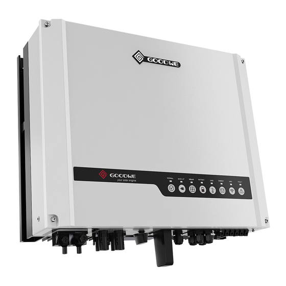
Page 7: Product Overview
hexagon head screw x2 pan head screw x8 flat head screw x5 warranty user manual fast WiFi fast installation installation Card fast installation x1 user manual x1 WiFi fast installation x1 warranty card x1 3.2 Product Overview 1. Battery input ports 2. - Page 8 installed with a sideways tilt. The connection area must point downwards. Refer to Figure 3.3-1. Figure 3.3-1 In order to achieve optimal performance, the ambient temperature should be lower than 45 °C. For the convenience of checking the LED lights and possible maintenance activities, please install the inverter at eye level.
-
Page 9: Mounting
300mm 300mm upward 500mm 500mm downward 500mm 300mm 300mm front both sides 500mm 500mm Figure 3.3-3 3.4 Mounting Remember that this inverter is heavy! Please be carefully when lifting out from the package. 1. Use the wall-mounted bracket as a template and drill 6 holes on the wall, 10 mm in diameter and 80 mm deep. -
Page 10: Electrical Connection
457mm 229mm 117mm 105mm 400mm Figure 3.4-1 Figure 3.4-2 detail b detail a Figure 3.4-3 Figure 3.4-4 flat head screw paklock Figure 3.4-5 Figure 3.4-6 4. Electrical Connection 4.1 AC Output Connection Before connecting to Grid and Load, please install a separate AC breaker (250VAC/30A)between inverter and Grid. - Page 11 Please follow below steps to implement AC connection: 1. Check the grid voltage and frequency at the connection point of the inverter. It should meet GoodWe product Spec. 2. Measure the impedance between neutral cable and earth cable, make sure it is not excess than 10 ohm.
-
Page 12: Pv Connection
AC cover AC terminal cable waterproof ring screw cap insulator crimp Figure 4.1-2 Figure 4.1-3 L----line N----neutral PE----earth cable core section after crimp back-up grid terminal terminal Figure 4.1-4 Figure 4.1-5 pan head screw Figure 4.1-6 Figure 4.1-7 4.2 PV Connection Before connecting the PV panels, ensure the plug connectors have the correct polarity. - Page 13 Check the short-circuit current of the PV string. The total short-circuit current must not exceed the inverter’s maximum PV current. PV array should not be connected to the grounding conductor. Must be use PV plugs in accessory bag. The minimum array insulation resistance to ground that system designer or installer must meet when selecting the PV panel and system design, based on the minimum value that the design of the PV functional grounding in the inverter was based on.
-
Page 14: Battery Connection
inverter side 2.5~4mm 2.5~4mm compress by professional tool Figure 4.2-3 4.3 Battery Connection Before connecting to battery, please install a separate DC breaker (60A for GW3648D-ES and 120A for GW5048D-ES) between inverter and battery. This will ensure the inverter can be securely disconnected during maintenance. Be aware of electric shock and chemical hazards! It is a normal phenomenon that electric arc occurs when connecting battery to the inverter without use a DC breaker. - Page 15 500Ah. Please follow below steps to implement battery connection: 1. Check the nominal voltage of batteries. The nominal input voltage should meet GoodWe product Spec. 2. Disconnect DC breaker between inverter and battery. 3. Disconnect screw cap from insulator.
-
Page 16: Rs485 Communication Connection
cable waterproof ring battery terminal insulator crimp screw cap battery cover Figure 4.3-2 Figure 4.3-3 + ----red cable ----black cable cable core section after crimp positive negative terminal terminal Figure 4.3-4 Figure 4.3-5 hexagon head screw pan head screw Figure 4.3-6 Figure 4.3-7 4.4 RS485 Communication Connection... - Page 17 EzMeter is a equipment for energy measurement developed by GoodWe EzMeter battery (Li-Ion) RS485 RS485 Figure 4.4-1 Please follow below steps to implement RS485 connection: 1. Remove RS485 waterproof assembly from inverter. 2. Disconnect screw cap from insulator. 3. Disconnect waterproof ring from insulator.
-
Page 18: Wifi Communication Connection
RS485 cover cable waterproof ring crystal head screw cap insulator Color Function RESERVED orange/white RESERVED orange RX_RS485B green/white RESERVED blue RESERVED blue/white RX_RS485A green TX_RS485B brown/white TX_RS485A brown RS485 waterproof assembly Figure 4.4-2 4.5 WiFi Communication Connection Install the antenna to inverter. Refer to Figure 4.5-1. Figure 4.5-1 4.6 USB Communication Connection The USB communication is used for firmware update only!... -
Page 19: Led Lights Illustration
insert USB data cable open USB cover Figure 4.6-1 5. LED Lights Illustration Inverter Status LED Color Inverter Status Note LED Display Status Blink 1s on 1s off WIFI link NG WIFI link OK,Internet NG Blink 2.5s on 2.5s off Wifi Yellow WIFI link OK,Internet OK... -
Page 20: Specifications
Utility Loss Grid disconnected Fac Failure Grid frequency no longer within permissible range Consistent Failure Machine parameter consistent fault Device Failure Device internal fault PV Over Voltage Overvoltage at DC input Over Temperature Overtemperature on the case Isolation Failure Ground insulation impedance is too low Ground I Failure Overhigh ground leakage current... - Page 21 Max. DC current (A) 15/15 No. of DC connectors No. of MPPTs 2(can parallel) DC connector SUNCLIX / MC4 (Optional) Battery Lead-acid or Li-Ion Lead-acid or Li-Ion Battery Type 40-60 Battery voltage range (Vdc) 4600 2300 MAX Discharge power (W) 5-50 A continuous, programmable Charge current (A) 100~500Ah(depending requirement)
-
Page 22: Certificates
AC over current protection Integrated Insulation monitoring Integrated Certifications&Standards VDE4105, VDE 0126-1-1+A1, G83/2, G59/2, AS4777.2/.3, Grid regulation IEC62109-2 Safety IEC62109-1&-2, AS3100, IEC62040-1 EN61000-6-1, EN61000-6-2, EN61000-6-3, EN61000-6-4, EN61000-3-11, EN61000-3-12 General Data Dimensions (WxHxD) 516*440*184mm Weight (kg) Mounting Wall bracket Ambient temperature -20~60°C(>45°C derating)... - Page 23 GoodWe (Europe) GoodWe (Australia) GoodWe (UK) GoodWe (China) Mürwikerstr. 59 74 Tarana Avenue, 93 Caversham Place No.189 Kunlunshan Rd., SND, 24943 Flensburg Germany Glenroy VIC 3046, Australia Sutton Coldfield B73 6HW Suzhou, 215163, China T: 0049 461 5897 0235 T: +61 3 9972 9938 uk@goodwe.com.cn...
Need help?
Do you have a question about the ES Series and is the answer not in the manual?
Questions and answers