Goodwe MT series User Manual
Hide thumbs
Also See for MT series:
- Introduction manual (69 pages) ,
- User manual (23 pages) ,
- Quick installation manual (2 pages)
Table of Contents
Advertisement
Quick Links
Advertisement
Table of Contents

Related Manuals for Goodwe MT series


Summary of Contents for Goodwe MT series
- Page 1 MT Series User Manual SOLAR INVERTER enquiries@goodwe.co.uk...
-
Page 2: Table Of Contents
1 Safety and warning ....................01 2 Product introduction ................... 02 2.1 Intended usage ..................02 ..............03 2.2 Inverter Overview ................05 2.3 Technical description ............2.4 Package ......3 Mounting ..........................08 ..............08 3.1 Mounting instruction .............. -
Page 3: Product Introduction
GW75KHV-MT model type. The MT series which is a Four MPPT, three phase transformer-less grid-connected inverter is a crucial unit between the PV MT Series have been designed and tested strictly according to the international safety regulation. As electrical and string and the utility grid in the PV power system. -
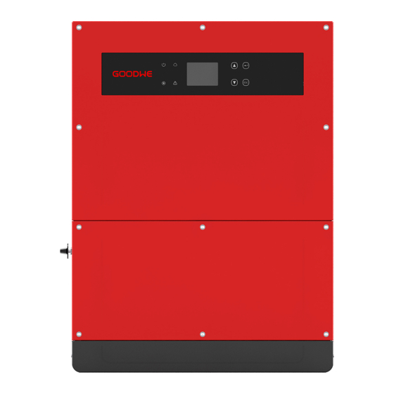
Page 4: Inverter Overview
(different Model types with different types of utility grid as below) Note: Image shown here is for reference only, actual product you receiver may differ. MT series GW50K-MT and GW60K-MT support four different types of grid. please refer to Figure 2.1-2 Item Name... -
Page 5: Technical Description
2.4 Package PV string voltage is transmitted to DC BUS via BOOST circuit. The MT series is equipped with four MPPTs for four DC inputs to ensure that the maximum power is utilized even in different PV 2.4.1 Unpacking and inspection installation condition. -
Page 6: Mounting
A nameplate is attached to one side of the inverter. It provide information on type inverter, along with the most important from installation site. specifications, marks of certifications, website and serial number, which is available and identified by Goodwe. Installation the unit at eye level for easily buttons operation and display Read Carry out the installation vertically or tilt backward no more than 15 degrees, no lateral tilt, and wiring area should be downward, which is shown in Figure 3.2.1-1. -
Page 7: Electrical Connection
(2) Fix the wall mounting bracket on the wall with six expansion bolts in accessory bag. L3 ----- Live Wire 3 (3) Carry the inverter with the handles on both sides of the inverter of MT series, which is shown in Figure 3.2.2-3. N ----- Neutral Wire (4) Place the inverter on the wall-mounted bracket as illustrated in Figure 3.2.2-4 , 3.2.2-5... - Page 8 The inverter is equipped with earth terminal according to the requirement of EN 50178. The MT series has four PV input area PV1 input, PV2 input, PV3 input, PV4 input, each with MPP tracker. The four PV input works All non-current carrying exposed metal parts of the equipment and other enclosures in the PV power system should be grounded.
-
Page 9: Communication Connection
RS485 RS485 RS485 Figure 3.4.2-1 The connection steps of RS485 communication of MT series are as follows: Remove the waterproof kit of RS485 cover with screwdriver. Remove the screw cap of the cable gland. Remove the one-hole sealing ring. Block them with non-conductive insulator Insert the RS485 cable through the components as the followings: screw cap, one-hole sealing ring, insulation body and sheetmetal parts. -
Page 10: System Operation
After the configurations are completed, please register on the website http://www.goodwe.com.cn Region ④ The WiFi module installation of MT series is shown in Figure 3.4.3-1. (2) Display area Area①——Flow of Power Generated: Area① indicates the flow of Power. Full line (—)between inverter and the grid means the grid is available but inverter is not yet feeding power at the time. - Page 11 Configuration for inverter equipped with WiFi Configuration for inverter equipped with RS485 Normal Error Log Utility Over Error Log Utility Over Down Down Down Down Enter Date&Time Loss Temperatur Enter Date&Time Loss Temperatur …………. …………. Language 13:12:25 13:29:25 Language 13:12:25 13:29:25 Histogram 2012-03-25...
- Page 12 (4) Menu introduction: Area③——Histogram Display: Area③ uses histogram to demonstrate the average power generation at each hour from 4:00am to 8:00pm on one day. Each columnar points 20 scale, the left top area shows the maximum rated power generation each hour for inverter. This area can display information in different modes, There are 5 display modes in total: real-time mode, hour mode, day mode, month mode, year mode.
-
Page 13: Wifi Reset & Wifi Reload
It is adjustable through special software ,if you want to use it ,please contact with after sales. 4. Turn on the AC breaker. Check the inverter work normal. The methods document of using the software can download from goodwe website or contact with after sales. 5 Troubleshooting If the Inverter is not able to work properly, please refer to the following instructions before contact your local service. -
Page 14: Overvoltage Category Definition
Type of Fault Trouble shooting 5.1 Overvoltage category definition 1.Check the impedance between Ground and PV (+) & PV (-) , The impedance value must be greater than 100k ,make sure the inverter is earthed. Isolation Failure Ω Category I : applies to equipment connected to a circuit where measures have been taken to reduce 2.Contact local service office for help if the problem still exists. -
Page 15: Technical Parameters And Block Diagram
6 Technical parameters and block diagram Technical Data GW75KHV-MT GW50K-MT GW60K-MT Ⅱ DC SPD Protection Integrated(Type 6.1 Technical parameters Ⅱ AC SPD Protection Integrated(Type Residual Current Monitoring Unit Technical Data GW50K-MT GW60K-MT GW75KHV-MT Output Over Current Protection PV String Input Data Output Short Protection Output Over Voltage Protection Max.DC Input Power(W) -
Page 16: Maintenance
7.1 Clearing MT series inverter is equipped with three fans on its left side. The fan intakes and handle covers should be cleaned yearly with a vacuum cleaner. For more thorough cleaning, completely remove the fans. -
Page 17: Checking The Electrical Connection
7.3 Checking the Electrical Connection 1. Check if the AC or DC wire is loose. 2. Check if the earth wire is reliable grounding. 3. Check if the waterproof covers of RS485 and USB port is fasten. 4. please use torque wrench to tighten the AC and battery terminal wiring connection once a year;Followed 3.3 torque instruction.
Need help?
Do you have a question about the MT series and is the answer not in the manual?
Questions and answers