Goodwe DNS Series User Manual
Grid-tied pv
Hide thumbs
Also See for DNS Series:
- User manual (47 pages) ,
- Quick installation manual (16 pages) ,
- Manual (83 pages)
Table of Contents
Advertisement
Advertisement
Table of Contents

Related Manuals for Goodwe DNS Series


Summary of Contents for Goodwe DNS Series
- Page 1 User Manual Grid-Tied PV Inverter DNS Series V1.6-2022-01-20...
-
Page 2: Table Of Contents
1 Symbols ..........................2 Safety Measures & Warning ................3 Product Introduction ..................3.1 Inverter Overview ........................04 3.2 Package ..............................05 4 Installation ........................4.1 Mounting Instructions ........................05 4.2 Equipment Installation ........................06 4.3 Electrical Connection ......................... 07 4.4 Communication Connection ...................... -
Page 3: Symbols
1 Symbols Failure to observe warnings indicated in this manual may result in injury. Recyclable materials Danger of high voltage & electric shock This side up - The package must always have the arrows point up Don't touch, hot surface! No more than six (6) identical packages be stacked on each other. -
Page 4: Safety Measures & Warning
2 Safety Measures & Warning The DNS series inverter of GoodWe Technologies Co., Ltd. (hereinafter referred to as GOODWE) strictly conforms to related safety rules in design and test. Safety regulations relevant to the location shall be followed during installation, commissioning, operation and maintenance. - Page 5 Make sure that there is no risk of water or dust entering terminals / holes. GOODWE provides standard manufacture warranty to inverter products, which will be delivered with the product. We also provide prepaid warranty extension solution to our customer. You can find the details about the terms and solutions from official website: https://en.goodwe.com/...
-
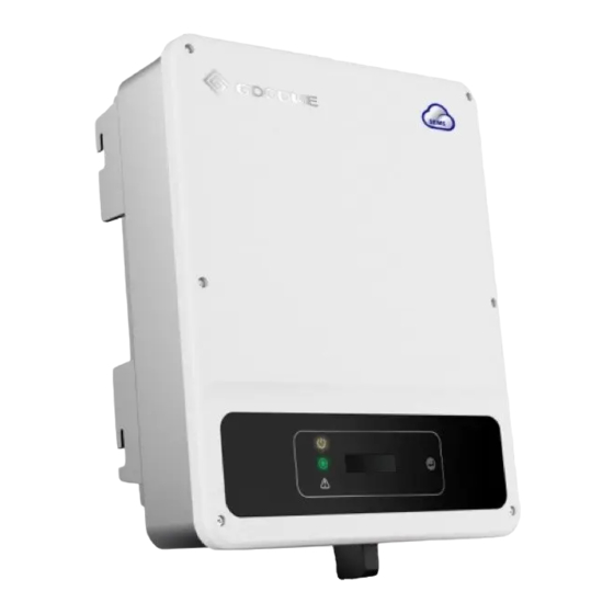
Page 6: Product Introduction
3 Product Introduction 3.1 Inverter Overview WiFi/4G/LAN/GPRS Communication PV Input Terminal DC Switch Module Port or RS485 Communication Cable Port DRED/CT/Remote Shut AC Output down Communication Terminal Cable Port Button PE Terminal Mounting Plate Heat Sink Item Name Description PV Input Terminal For PV string connection During normal operation, it can shut down the DC Switch... -
Page 7: Package
3.2 Package The units have been thoroughly tested and strictly inspected before delivery. Damage may still occur during shipping. 1. Check the package for any visible damage upon receiving. 2. Check the inner contents for damage after unpacking. 3. Check the package list below. Mounting Negative DC Postive DC... -
Page 8: Equipment Installation
4.2 Equipment Installation 4.2.1 Select installation location Please take the following points into consideration when you are selecting a proper location to install the inverter. • Please choose appropriate mounting methods and installation location in terms of weight and dimensions of the inverter. •... -
Page 9: Electrical Connection
195mm Expansion Pipe Wall-Mounting Bracket 195mm Self-tapping Screws 130mm The lock is not included in the package. Customers need to prepare it by themselves if need. 4.2 Equipment Installation 4.2.1 Select installation location 1. Check the grid voltage and frequency to see whether it complies with the required voltage and frequency. - Page 10 When unplugging the AC terminals, press 7-9mm the button and hold it to unlock it. unlock lock Torque 0.7~0.9N.m Make sure the terminal is rotated to the lock position before the inverter started. AC cable illustration : Grade Description Value 10~12mm Section area of 2.5~4mm²...
- Page 11 4.3.2 AC Circuit Breaker And Residual Current Protection Device In order to ensure that the inverter can be safely and reliably disconnect from the power grid, please install an independent bipolar circuit breaker to protect the inverter. The inverter can exclude the possibility of DC residual currents to 6mA in the system, where an external RCD is required in addition to the build-in RCMU.
- Page 12 2. The open circuit voltage of the PV strings cannot exceed the maximum input voltage of the inverter. 3. Only DC connectors provided by GoodWe are permitted. 4. Do not connect the positive and negative pole to the PE cable (Ground cable). Otherwise, the unit may be damaged.
- Page 13 AMPHENOL SERIES QC4.10 SERIES Note: The actual DC connector used is as shown in the accessory box. DC cable specification: Name Explanation Cold-pressed terminal Screw M5*14 Yellow and green line / 10AWG Note: The DC Cable should be dedicated PV cable. The installation method of DC connector.
-
Page 14: Communication Connection
4.4 Communication Connection 4.4.1 USB Connection USB interface is used for after-sales service team to repair inverter only. Not allowed for any other purposes. Step 1: Unscrew this plate from inverter. Step 2: Insert the USB data cable. 4.4.2 RS485 Communication This function is only applied to inverters with RS485. - Page 15 Please follow the steps below to complete RS485 communication connection. Step 1: Unscrew this plate from inverter. Step Single hole RS485 Thread the cable through the plate, and seal ring communication board Cable connect the RS485 cable on the 6-pin terminal.
- Page 16 After configuration, please create PV station using the monitoring portal website. 4.4.4 Export Power Limit Connection Diagram Connect the Power Limiting device CT shown below. white & Black Wire Black Wire Inverter Switch Board Router 4.4.5 DRED / Remote Shutdown / CT (Power Limit Device) Connection DRED (Demand response enabling device) is only for Australian and New Zealand installations, in compliance with Australian and New Zealand safety requirements.
- Page 17 Step 2-1 For DRED: Thread the cable through the connector and connect to the terminal. Function 6.5mm COM/DRM0 REFGEN DRM4/8 25mm DRM3/7 Lock Screw Cap Insulator DRM2/6 Cable Single hole RS485 DRM1/5 seal ring communication board Step 2-2 For remote shutdown: Thread the cable through the connector and connect to the terminal.
- Page 18 Note: 1. Compatible DRED commands are DRM0, DRM5, DRM6, DRM7, DRM8. 2. Please set up power limit function at local setting page once all connection steps are done. 3. The CT is directional. Please make sure the limit buckle is connected to the output live wire (L) of the inverter.
-
Page 19: System Operation
5 System Operation 5.1 LCD Panel And LED 5.1.1 Indicator Lights Indicator lights in Yellow/Green/Red correspondently refer to: Indicator Status Explanation ON = WiFi connected/active BLINK 1 = WiFi system resetting Power BLINK 2 = Not connect to router BLINK 3 = WiFi server problem BLINK = RS485 connected OFF = WiFi not active On = Inverter is feeding power... - Page 20 5.2.2 Set Safety Country After powering on for the first time, the inverter prompts Select Country/Region, please short press until "GW3000D-NS Pac=****.0W" is displayed, and then set the safety region. The inverter cannot be connected to the grid before the safety-related area is set. If display shows "GW3000D-NS Pac=****.0W", then long press the button to enter the second level menu.
- Page 21 5.2.6 Menu Introduction • When the PV panel is feeding power to the inverter, the LCD displays the main menu. • The initial display is the first item to the main menu, and the interface displays the current status of the system. In the initial state, the LCD displays "Waiting". Under power generation mode, the LCD displays "Normal".
- Page 22 Main Menu Sub Menu Long press Normal 50Hz Grid Default Pac=2595.5W Short press E-Today=15.2KWh Long press Lock Pac=2595.5W Short press E-Total=533.17KWh Pac=2595.5W Short press Long press No Error Vpv=325.2/325.5V Pac=2595.5W E01 110822 01:01 Short press Ipv=4.1/4.1A Pac=2595.5W Short press to select 50Hz Grid Default safety country Short press...
- Page 23 • Set language Short press the button to enter "Set Language". Long press the button to enter the sub menu. Short press the button to browse the languages available. • Set time Short press the button to switch from "Set Language" to "Set Time". Then long press the button to enter the sub menu.
- Page 24 Short Press to select number 0 ~ 9 Shadow MPPT ON/Shadow MPPT OFF Password:1111 Pac=XXXX.XW Short press Short press Long Short Press to select Power Limit ON/Power Limit OFF press Password:1111 Short number 0 ~ 9 Pac=XXXX.XW press Long Short press press Short press Short Press to select...
-
Page 25: Error Message
Main Menu Main Menu Sub Menu Long Press Wait Normal Auto Test Auto Testing Pac=XXXX.XW Pac=XXXX.XW Short Main Menu Press Short Press To Check The Value Auto Test Result Pac=XXXX.XW Choose auto test type between "Remote" and "Local" before starting the test. Under "Remote" mode, the default setting is 1 and cannot be modified. -
Page 26: Wi-Fi Reset & Wi-Fi Reload
5.4 Wi-Fi Reset & Wi-Fi Reload These functions are only available for Wi-Fi model inverters. Wi-Fi reload function is used to reconfigure the Wi-Fi to default. Please configure the Wi-Fi again after using the function. Short press the button until the LCD displays "Wi-Fi Reset", then long press the button until the LCD displays "Wi-Fi Resetting…". -
Page 27: Special Adjustable Setpoints
5.6 Special Adjustable Setpoints The inverter has a field in which the user can set functions, such as trip points, trip times, reconnect times, active and inactive QU curves and PU curves. It is adjustable through SolarGo app. 5.6.1 PF Power Curve Mode PF power curve mode can be modified by Modbus communication method, specifically according to the machine Modbus address and Modbus register value, according to the set range to set the corresponding value. - Page 28 5.6.2 PU Curve Mode The PU curve mode can be modified by Modbus communication method, specifically according to the machine Modbus address and Modbus register value, according to the set range to set the corresponding value. 5.6.3 QU Curve Mode QU curve mode can be modified by Modbus communication, specifically according to the machine Modbus address and Modbus register value, according to the set range to set the corresponding value.
-
Page 29: Troubleshooting
6 Troubleshooting In most situations, the inverter requires very little maintenance. However, if the inverter is not working properly, please try the following troubleshooting solutions: • When a problem occurs, the red (fault) LED indicator on the front panel will light up and the LCD screen will display the type of fault. - Page 30 Relay-Check Failure DCI Injection High 1. Turn off DC switch of the inverter. Inverter 2. Wait till the LCD light is off. EEPROM R/W Failure 3. Turn on the DC switch and make sure it is connected. Failure 4. If the problem still exists, contact local service office for help. SPI Failure DC BUS High GFCI Failure...
-
Page 31: Technical Parameters
7 Technical Parameters Technical Data GW2900D-NS GW3000D-NS GW3600D-NS GW4200D-NS GW5000D-NS GW6000D-NS Input Max.Input Power (W) 4000* 3900* 4680* 5460* 6500* 7200 Max.Input Voltage (V) MPPT Operating Voltage 80-435 80~550 80~550 80~550 80~550 80~550 Range (V) MPPT Voltage Range at 150~550 180~550 210~550 240~550... - Page 32 DC Reverse Polarity Integrated Protection Anti-islanding Protection Integrated AC Overcurrent Integrated Protection AC Short Circuit Integrated Protection AC Overvoltage Integrated Protection DC Switch Optional DC Surge Arrester Type III (Type Type III Type III Type III Type III Type III II Optionl)...
- Page 33 Technical Data GW3000T-DS GW3600T-DS GW4200T-DS GW5000T-DS GW6000T-DS Input Max.Input Power (W) 3900* 4680* 5460* 6500* 7200 Max.Input Voltage ( V) MPPT Operating Voltage Range 80~550 80~550 80~550 80~550 80~550 MPPT Voltage Range at Nominal 130~550 150~550 170~550 200~550 240~550 Power (V) Start-up Voltage (V) Nominal Input Voltage (V) Max.
- Page 34 AC Short Circuit Protection Integrated AC Overvoltage Protection Integrated DC Switch Optional DC Surge Arrester Type III(Type II Optional) AC Surge Arrester Type III DC Arc Fault Circuit Interrupter Optional Remote Shutdown Optional General Data Operating Temperature Range -25~60 (℃) Relative Humidity 0~100% Max.
- Page 35 Note: Overvoltage Category Definition Applies to equipment connected to a circuit where measures have been taken to reduce transient Category Ⅰ overvoltage to a low level Applies to equipment not permanently connected to the installation. Examples are appliances, Category Ⅱ portables tools and other plug- connected equipment Applies to a fixed equipment downstream of and including the main distribution board.
-
Page 36: Power Off The Inverter
8 Maintenance Regular maintenance ensures a long operating life and optimal efficiency of the entire PV plant. Caution: Before maintenance, please disconnect the AC breaker, and disconnect DC breaker then. Wait for 5 minutes until the residual voltage totally released. 9 Power off the inverter When operating and maintaining the inverter, please power off the inverter. - Page 37 Offical Website GoodWe Technologies Co., Ltd. No. 90 Zijin Rd., New District, Suzhou, 215011, China www.goodwe.com service@goodwe.com Local Contacts...
Need help?
Do you have a question about the DNS Series and is the answer not in the manual?
Questions and answers