
Related Manuals for mikroElektronika EEPROM


Summary of Contents for mikroElektronika EEPROM
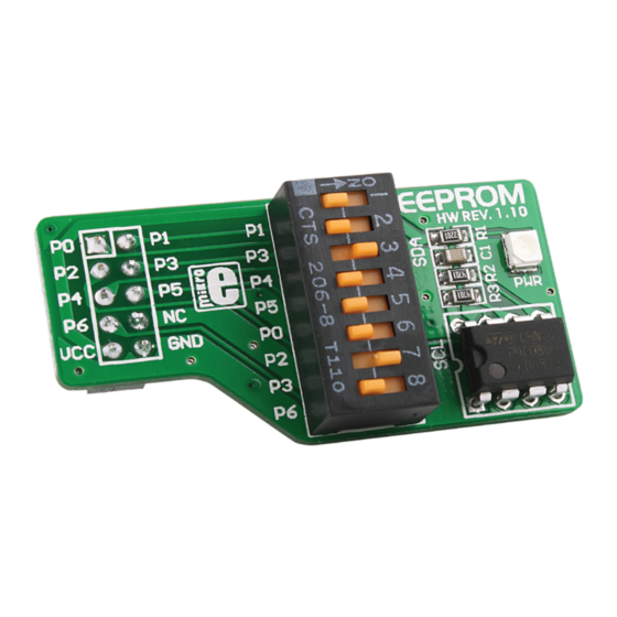
- Page 1 EEPROM Expand development system capabilities by adding 8K EEPROM memory accessory board Arrow.com. Downloaded from...
-
Page 2: To Our Valued Customers
TO OUR VALUED CUSTOMERS I want to express my thanks to you for being interested in our products and for having confidence in Mikroelektronika. The primary aim of our company is to design and produce high quality electronic products and to constantly improve the performance thereof in order to better suit your needs. - Page 3 Table of Contents Introduction to EEPROM Key features System Specification 1. Connecting with development system 2. DIP switch settings 3. Schematic 4. Dimensions Arrow.com. Arrow.com. Arrow.com. Downloaded from Downloaded from Downloaded from Page 3...
-
Page 4: Key Features
Accessory board is designed for usage with various development systems and other MCU device with 2x5 header. EEPROM accessory board is designed to add 8K of EEPROM memory to microcontroller via serial I 2 C communication. Key features Pads with female 2x5 header on back side of the board. -
Page 5: System Specification
System Specification power supply 3.3V or 5V DC depends on MCU power supply power consumption min 0.6uA (standby mode) max 3mA (write mode at 100kHz) board dimensions 45.34 x 23.88 mm (1.78 x 0.94“) weight ~9g (0.02 lbs) Arrow.com. Arrow.com. Arrow.com. - Page 6 Figure 1-2: Connecting EEPROM EEPROM is designed for connection with 2x5 male headers on development system port’s via 2x5 female header on accessory board. Every pin on 2x5 female header is marked so for proper orientation just compare marks between accessory board and development system.
- Page 7 In order to connect EEPROM to different development system it is necessary to make settings on DIP switch SW1. Every pin on DIP switch SW1 is connected to different pin of 2x5 female header. In table 1 is given list...
- Page 8 100nF 24C08 Figure 3-1: Connection schematic Arrow.com. Arrow.com. Arrow.com. Arrow.com. Arrow.com. Arrow.com. Arrow.com. Arrow.com. Downloaded from Downloaded from Downloaded from Downloaded from Downloaded from Downloaded from Downloaded from Downloaded from Page 8...
- Page 9 45.34mm(1.78'’) 7.51mm(0.30'’) Figure 4-1: Dimensions Arrow.com. Arrow.com. Arrow.com. Arrow.com. Arrow.com. Arrow.com. Arrow.com. Arrow.com. Arrow.com. Downloaded from Downloaded from Downloaded from Downloaded from Downloaded from Downloaded from Downloaded from Downloaded from Downloaded from Page 9...
- Page 10 Notes: Arrow.com. Arrow.com. Arrow.com. Arrow.com. Arrow.com. Arrow.com. Arrow.com. Arrow.com. Arrow.com. Arrow.com. Downloaded from Downloaded from Downloaded from Downloaded from Downloaded from Downloaded from Downloaded from Downloaded from Downloaded from Downloaded from Page 10...
- Page 11 No part of this manual, including product and software described herein, may be reproduced, stored in a retrieval system, translated or transmitted in any form or by any means, without the prior written permission of MikroElektronika. The manual PDF edition can be printed for private or local use, but not for distribution.
- Page 12 EEPROM v1.10 If you want to learn more about our products, please visit our website at www.mikroe.com If you are experiencing some problems with any of our products or just need additional information, please place your ticket at www.mikroe.com/en/support If you have any questions, comments or business proposals, do not hesitate to contact us at office@mikroe.com...
Need help?
Do you have a question about the EEPROM and is the answer not in the manual?
Questions and answers