Table of Contents
Advertisement
Quick Links
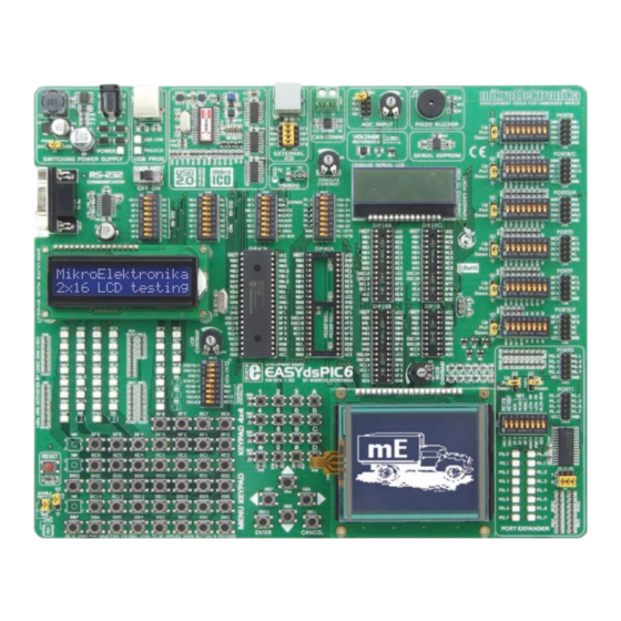
EasydsPIC6
™
User manual
All MikroElektronika´s development systems represent irreplaceable tools for
programming and developing microcontroller-based devices. Carefully chosen
components and the use of machines of the last generation for mounting and
testing thereof are the best guarantee of high reliability of our devices. Due to
simple design, a large number of add-on modules and ready to use examples,
all our users, regardless of their experience, have the possibility to develop
their project in a fast and effi cient way.
Advertisement
Table of Contents

Related Manuals for mikroElektronika EasydsPIC6


Summary of Contents for mikroElektronika EasydsPIC6
- Page 1 EasydsPIC6 ™ User manual All MikroElektronika´s development systems represent irreplaceable tools for programming and developing microcontroller-based devices. Carefully chosen components and the use of machines of the last generation for mounting and testing thereof are the best guarantee of high reliability of our devices. Due to...
- Page 2 TO OUR VALUED CUSTOMERS I want to express my thanks to you for being interested in our products and for having confi dence in mikroElektronika. The primary aim of our company is to design and produce high quality electronic products and to constantly improve the performance thereof in order to better suit your needs.
-
Page 3: Table Of Contents
Development System EasydsPIC6 TABLE OF CONTENTS Introduction to EasydsPIC6 Development System ................4 Key Features ............................ 5 1.0. Connecting the System to a PC ....................6 2.0. Supported Microcontrollers ....................... 7 3.0. On-board dsPICprog Programmer .................... 8 4.0. mikroICD (In-Circuit Debugger) ....................10 5.0. -
Page 4: Introduction To Easydspic6 Development System
Development system: EasydsPIC6 product CD with relevant software Cables: USBcable Documentation: Manuals for EasydsPIC6, dsPICprog and mikroICD, quick guide for installing USB drivers, electrical schematic of the system System specification: Power Supply: over an AC/DC connector (7-23V AC or 9-32V DC); or... -
Page 5: Key Features
Development System EasydsPIC6 Key Features 16. Port expander 1. Power supply voltage regulator 17. Potentiometer for adjusting contrast of graphic display 2. On-board programmer’s USB connector 18. Graphic LCD connector 3. USB 2.0 programmer with mikroICD 19. Touch panel connector 4. -
Page 6: Connecting The System To A Pc
Step 2: Use the USB cable to connect the EasydsPIC6 development system to a PC. One end of the USB cable, with a USB connector of B type, should be connected to the development system, as shown in Figure 1-2, whereas the other end of the cable with a USB connector of A type should be connected to a PC. -
Page 7: Supported Microcontrollers
Development System EasydsPIC6 2.0. Supported Microcontrollers The EasydsPIC6 development system provides six separate sockets for dsPIC microcontrollers in DIP40, DIP28 and DIP18 packages. These sockets allow supported microcontrollers in dsDIP packages to be plugged directly into the development board. There are two sockets for dsPIC microcontrollers in DIP40 package, three sockets for dsPIC microcontrollers in DIP28 package and one socket for dsPIC microcontrollers in DIP18 package provided on the board. -
Page 8: On-Board Dspicprog Programmer
A programmer is a necessary tool when working with microcontrollers. It is used to load a hex code into the microcontroller and provides an interface between the microcontroller and a PC. The EasydsPIC6 has an on-board dsPICprog programmer. All you need is a .hex file to be loaded into the microcontroller using the dsPICFLASH program. - Page 9 Development System EasydsPIC6 Microcontroller pins for programming (PGD, PGC and MCLR) are not directly connected to the on-board programmer, but via a multiplexer. The multiplexer is used to disconnect the microcontroller pins used for programming from the rest of the board while the programming process is under way.
-
Page 10: Mikroicd (In-Circuit Debugger)
The process of testing and debugging is performed by monitoring the state of all registers within the microcontroller while operating in real environment. The mikroICD software is integrated in all dsPIC compilers designed by Mikroelektronika (mikroBASIC PRO, mikroC PRO, mikroPASCAL PRO etc). As soon as the mikroICD debugger starts up, a window called Watch Values, appears on the screen, Figure 4-1. -
Page 11: Icd Connector
Development System EasydsPIC6 5.0. ICD Connector The ICD connector enables communication between the microcontroller and an external ICD debugger/programmer from Microchip (ICD2 or ICD3). Jumpers J9 and J10 are used for selecting a pin to be fed with programming signals. For the programming signals to be sent to the microcontroller, it is necessary to place these jumpers in the appropriate position. -
Page 12: Power Supply
Development System EasydsPIC6 6.0. Power supply The EasydsPIC6 development system may use one of two power supply sources: 1. +5V PC power supply through the USB programming cable; and 2. External power supply source connected to an AC/DC connector provided on the development board. -
Page 13: Rs-232 Communication Module
PC and peripheral modules. RS-232 serial communication is performed through a 9-pin SUB-D connector and the microcontroller USART module. The EasydsPIC6 provides one RS-232 port. Depending on the microcontroller in use, it is necessary to set appropriate switches on the DIP switch SW7 or SW8 to enable connection between the microcontroller and the RS-232 communication module. -
Page 14: Can Communication Module
PC. In addition, such communication is widely used in industrial automation. The EasydsPIC6 uses the MCP2551 circuit for CAN communication. This circuit provides an interface between the microcontroller and some peripheral device. To enable connection between the microcontroller and MCP2551, it is necessary to set switches 6 and 8 on the DIP switch SW8 to ON position. -
Page 15: Voltage Reference Source
9.0. Voltage Reference Source The EasydsPIC6 development system provides an MCP1541 circuit which generates the voltage reference used for A/D conversion. The value of the voltage reference is 4.096V. This voltage is suppled to the microcontroller via the RB0 pin. For the RB0 pin to be fed with the reference voltage, it is necessary to set switch 7 on the DIP switch SW9 to ON position. -
Page 16: A/D Converter Test Inputs
Development System EasydsPIC6 10.0. A/D Converter Test Inputs An A/D converter is used for converting an analog voltage into the appropriate digital value. The A/D converter is linear, which means that converted number is linearly dependent on the input voltage value. The A/D converter built into the microcontroller converts an analog voltage value into a digital number. -
Page 17: Serial Eeprom Module
Development System EasydsPIC6 11.0. Serial EEPROM Module EEPROM (Electrically Erasable Programmable Read-Only Memory) is a built-in memory module used to store data that should be saved when the power supply goes off. The 24AA01 circuit can store up to 1Kbit data and uses serial I C module to communicate with the microcontroller via pins RF2 and RF3. -
Page 18: Ds1820 Temperature Sensor
-55 to 125°C and provides ±0.5°C accuracy for temperatures within the range of -10 to 85°C. A power supply voltage of 3V to 5.5V is required for its operation. It takes maximum 750ms for the DS1820 to calculate temperature with a 9-bit resolution. The EasydsPIC6 development system provides a separate socket for the DS1820. -
Page 19: Piezo Buzzer
Development System EasydsPIC6 13.0. Piezo Buzzer Due to a built-in piezo buzzer, the develompent system is capable of emitting audio signals. For the piezo buzzer to operate normally it is necessary to generate a voltage signal of specified frequency. The voltage signal is generated in the microcontroller by the appropriate code written to its memory. -
Page 20: Leds
EasydsPIC6 uses LEDs with current I=1mA. There are 42 LEDs on the EasydsPIC6 development system which visually indicate the state of each microcontroller I/O pin. An active LED indicates that a logic one (1) is present on the pin. In order to enable the pin state to be shown, it is necessary to select appropriate port (PORTB/C, PORTA/D, PORTE or PORTE/F) using the DIP switch SW12. -
Page 21: 4X4 Keypad
Development System EasydsPIC6 15.0. 4x4 Keypad The 4x4 keypad is a standard alphanumeric keypad connected to the microcontroller port PORTB. The performance of this keypad is based on the ‘scan and sense’ principle where pins RB8, RB9, RB10 and RB11 are configured as inputs connected to pull-down resistors. -
Page 22: Menu Keypad
16.0. MENU Keypad There is a set of push buttons serving as a navigation keypad called MENU provided on the EasydsPIC6 development system. It primarily consists of four push-buttons marked as left, right, up and down arrows. There are also two additional push buttons marked as ENTER and CANCEL. -
Page 23: Push Buttons
Development System EasydsPIC6 17.0. Push Buttons The logic state of all microcontroller input pins may be changed by means of push buttons. Jumper J15 is used to determine the logic state to be applied to the desired microcontroller pin by pressing the appropriate push button. The function of the protective resistor is to limit the maximum current, thus preventing the development system and peripheral modules from being damaged in case a short circuit occurs. -
Page 24: On-Board 2X16 Lcd
Development System EasydsPIC6 18.0. On-Board 2x16 LCD On-board 2x16 LCD display is connected to the microcontroller by means of a port expander. In order to use this display, it is necessary to set switches 1-6 on the DIP switch SW10 to ON position, thus connecting the on-board LCD to the port expander’s PORT1. DIP switch SW11 enables SPI communication between the port expander and the microcontroller. -
Page 25: 2X16 Lcd
19.0. 2x16 LCD The EasydsPIC6 development system provides an on-board connector for the alphanumeric 2x16 LCD. This connector is linked to the microcontroller via ports PORTB and PORTD. Potentiometer P4 is used to adjust display contrast. Switch 8 (LCD-BCK) on the DIP switch SW9 is used to turn the display backlight on/off. -
Page 26: 128X64 Graphic Lcd
Development System EasydsPIC6 20.0. 128x64 Graphic LCD 128x64 graphic LCD (GLCD) is connected to the microcontroller via ports PORTB, PORTD and PORTF and enables graphic content to be displayed. It has the screen resolution of 128x64 pixels, which allows diagrams, tables and other graphic content to be displayed. -
Page 27: Touch Panel
Development System EasydsPIC6 21.0. Touch Panel The touch panel is a thin, self-adhesive, transparent, touch-sensitive panel. It is placed over a GLCD. Its main function is to register pressure at some specific display point and to forward its coordinates in the form of analog voltage to the microcontroller. Switches 5, 6, 7 and 8 on the DIP switch SW12 are used for connecting the microcontroller and touch panel. -
Page 28: I/O Ports
Development System EasydsPIC6 22.0. Input/Output Ports Along the right side of the development system, there are six 10-pin connectors connected to the microcontroller’s I/O ports. Pins used for programming are not directly connected to the appropriate 10-pin connectors, but via the programmer’s multiplexer. Owing to DIP switch SW1-SW6, each connector pin can be connected to one pull-up/pull-down resistor. - Page 29 Development System EasydsPIC6 Pull-up/pull-down resistors enable you to set the logic level on all microcontroller’s input pins when they are in idle state. This level depends on the position of the pull-up/pull-down jumpers. The RD0 pin with the relevant DIP switch SW3, jumper J3 and push button RD0 with jumper J15 are used here for the purpose of explaining the performance of pull-up/pull-down resistors.
-
Page 30: Port Expander (Additional I/O Ports)
23.0. Port Expander (Additional Input/Output Ports) SPI communication lines and MCP23S17 circuit provide the EasydsPIC6 development system with means of increasing the number of available I/O ports by two. If the port expander communicates to the microcontroller over the DIP switch SW11 then the microcontroller pins RB10, RB11, RF6, RF2 and RF3 used for the operation of port expander, cannot be used as I/O pins. - Page 31 MikroElektronika shall assume no responsibility or liability for any errors, omissions and inaccuracies that may appear in this manual. In no event shall MikroElektronika, its directors, offi cers, employees or distributors be liable for any indirect, specifi c, incidental or consequential damages (including damages for loss of business profi...
- Page 33 Mouser Electronics Authorized Distributor Click to View Pricing, Inventory, Delivery & Lifecycle Information: mikroElektronika MIKROE-472...
Need help?
Do you have a question about the EasydsPIC6 and is the answer not in the manual?
Questions and answers