Table of Contents
Advertisement
Quick Links
Advertisement
Table of Contents

Related Manuals for mikroElektronika EasyPIC PRO v7


Summary of Contents for mikroElektronika EasyPIC PRO v7
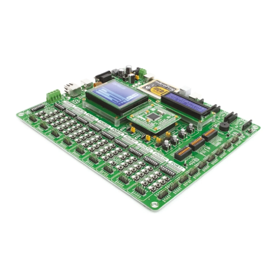
- Page 1 EasyPIC PRO microcontrollers supported Supports 3.3V and 5V devices Easily add extra boards Four connectors for each port Fast USB 2.0 programmer and The ultimate PIC board Dual Power Supply mikroBUS sockets Amazing Connectivity In-Circuit Debugger ® ™...
- Page 2 To our valued customers From the day one, we in MikroElektronika gave ourselves the highest possible goals in pursuit of excellence. That same day, the idea of EasyPIC development board was born. And we all grew together with EasyPIC ™...
-
Page 3: Table Of Contents
Introduction Communication Introduction ........UART via RS-232 . -
Page 4: Introduction
Introduction For the first time in history we have managed to combine all the features of BIGPIC6 and LV18F v6 boards, which supported high pin count PICs into the unique EasyPIC PRO v7. Supporting microcontrollers in both 5V ™ and 3.3V power supply technology, this board is truly fantastic tool for development. -
Page 5: It's Good To Know
It's good to know PIC18F87K22 is the default microcontoller! System Specification PIC18F87K22 is the default chip of EasyPIC PRO ™ - Great choice for both beginners and power supply Featuring nanoWatt XLP technology, it has 16 MIPS ™ professionals 7–23V AC or 9–32V DC operation, 128K bytes of linear program memory,... -
Page 6: Power Supply
Power supply Board contains switching power supply that creates stable voltage and current levels necessary powering each part of the board. Power supply section contains two power regulators: MC34063A, which generates VCC-5V, and MC33269DT3.3 which creates VCC-3.3V power supply, thus making the board capable of supporting both 5V and 3.3V microcontrollers. - Page 7 Smart engineering of EasyPIC PRO v7 develop- Power supply: via DC connector or screw terminals ™ ment board allowed us to support both 3.3V and (7V to 23V AC or 9V to 32V DC), 5V microcontrollers on a single board, which is or via USB cable (5V DC) almost 100 high pin count PIC devices.
-
Page 8: Default Mcu Card
Default MCU card Microcontrollers are supported using specialized MCU cards containing 104 pins, which Default MCU card that comes with the EasyPIC PRO v7 package is shown on Figure ™ are placed into the on-board female MCU socket. Currently, there are three types of cards: 4-1. - Page 9 10uF 10uF MCLR# 22pF PIC18F87K22 MCLR PGC/RB6 OSC2 80pin TQFP OSC2/RA6 VCAP OSC1 VCCcore/Vcap/VDD OSC1/RA7 16MHz PGD/RB7 22pF 10uF RF4/DP RF4/D+ RF3/DM RF3/D- HD1A HD3C RF4/DP 100nF 100nF 100nF 10uF RF3/DM RF1/USB ENR/RF0 10uF 10uF Figure 4-2: Default MCU card schematics EasyPIC PRO page 9...
- Page 10 How to properly place your MCU card into the socket? Before you plug the microcontroller card into EasyPIC PRO v7 board MCU socket. Place the MCU everything is placed correctly and press the MCU ™ the socket, make sure that the power supply is card over the socket, so each male header encloses card until it is completely plugged into the socket turned off.
-
Page 11: Supported Microcontrollers
Other supported MCU cards MikroElektronika currently offers total of five populated MCU cards with different microcontrollers. You can also purchase empty PCB cards that you can populate on your own and solder any supported microcontroller you need in your development. This way your EasyPIC PRO v7 board becomes truly flexible and ™... -
Page 12: On-Board Programmer
On-board programmer What is mikroProg ™ mikroProg is a fast USB 2.0 programmer with mikroICD hardware In-Circuit Debugger. Smart engineering allows mikroProg ™ ™ ™ to support all nearly 100 PIC18 devices in a single programmer. It also features a powerful mikroICD ™... - Page 13 List of microcontrollers supported with mikroProg ™ Here's the list of all microcontrollers which are supported with mikroProg programmer and debugger on EasyPIC PRO v7 board. The list may grow with each new ™ ™ release of mikroProg Suite ™ for PIC ®...
-
Page 14: Installing Programmer Drivers
Installing programmer drivers On-board mikroProg requires drivers in order to work. ™ Drivers can be found on the link below: http://www.mikroe.com/downloads/get/1201/ mikroprog_for_pic_drivers_v200.zip When you locate the drivers, please extract files from the ZIP archive. Folder with extracted files contains sub folders with drivers for different operating systems. -
Page 15: Programming Software
Programming software mikroProg Suite for PIC ™ ® Installation wizard - 6 simple steps On-board mikroProg ™ programmer requires special programming software called mikroProg Suite for PIC ™ ® . This software is used for programming all of Microchip ® microcontroller families, including PIC10, PIC12, PIC16, PIC18, dsPIC30/33, PIC24 and PIC32. -
Page 16: Mikroicd™ - In Circuit Debugger
™ tools on the market. Supported Compilers All MikroElektronika compilers, mikroC, mikroBasic and mikroPascal for PIC , dsPIC and PIC32 natively support ®... - Page 17 ™ Here is a short overview of which debugging commands are supported in MikroElektronika compilers. You can see what each command does, and what are their shortcuts when you are in debugging mode. It will give you some general picture of what your debugger can do.
-
Page 18: Input/Output Group
Input/Output Group One of the most distinctive features of EasyPIC v7 are it’s Input/Output PORT groups. They ™ add so much to the connectivity potential of the board. Everything is groupped together It took us a while to realize that having PORT headers, PORT buttons and Figure 6-1: I/O group contains PORT headers, tri-state pull PORT LEDs next to each other, and groupped together, makes development up/down DIP switch, buttons and LEDs all in one place... - Page 19 DIP switches. These headers are corresponding MCU pin when button is neccessary Microcontroller SMD resistor all compatible with over 70 MikroElektronika accessory pressed, for each I/O port separately. to place a current limiting current boards, and enable simple connection.
-
Page 20: Mikrobus ™ Sockets
Success of the USB standard comes from it’s simplicity of usage and high and reliable data transfer rates. As we in MikroElektronika see it, Plug-and-Play devices with minimum settings are the future in embedded world too. This is why our engineers have come up with a simple, but brilliant pinout with lines that most of today’s accessory boards require, which almost completely eliminates the need... -
Page 21: Click Boards ™ Are Plug And Play
™ ™ ™ Click Boards are plug-n-play! ™ MikroElektronika portfolio of over 200 accessory boards is now enriched by hardware configuration. Just plug and play. Visit the Click boards webpage ™ an additional set of mikroBUS compatible Click Boards . Almost each month for the complete list of available boards: ™... -
Page 22: Uart Via Rs-232
UART via RS-232 UART (universal asynchronous receiver/ transmitter) is one of the most common ways of Enabling RS-232 exchanging data between the MCU and peripheral components. It is a serial protocol with separate transmit and receive lines, and can be used for full- duplex communication. -
Page 23: Uart Via Usb
UART via USB Modern PC computers, laptops and notebooks are no longer equpped with RS-232 connectors and Enabling USB-UART UART controllers. They are nowdays replaced with USB connectors and USB controllers. Still, certain technology enables UART communication to be done over USB connection. Controllers such as FT232RL from FTDI®... -
Page 24: Usb Device Communication
USB device communication USB is the acronym for Universal Serial Bus. This is a very popular industry standard that Enabling USB defines cables, connectors and protocols used for communication and power supply between computers and other devices. EasyPIC PRO ™ contains USB DEVICE connector (CN9) which enables microcontrollers that support USB communication to establish a connection... -
Page 25: Ethernet Communication
Ethernet communicaton Ethernet is a popular computer networking technology for local area networks (LAN). Enabling Eth. LEDs Systems communicating over Ethernet Figure 11-1: divide a stream of data into individual Ethernet connection schematics packets called frames. Each frame contains source and destination addresses and error- checking data so that damaged data can be detected and re-transmitted. -
Page 26: Lcd 2X16 Characters
LCD 2x16 characters Liquid Crystal Displays or LCDs are cheap and popular way of representing information to the end user of some electronic device. Character LCDs can be used to represent standard and custom characters in the predefined number of fields. -
Page 27: Glcd 128X64Px
GLCD 128x64 Graphical Liquid Crystal Displays, or GLCDs are used to GLCD module to perfectly and firmly fit into place. display monochromatic graphical content, such as text, Display connector is routed to PORTB (control lines) images, human-machine interfaces and other content. and PORTD (data lines) of the microcontroller sockets. -
Page 28: Touchpanel Controller
Touchpanel controller Touchpanel is a glass panel whose surface is covered touchpanel controller and connector for 4-wire resistive with two layers of resistive material. When the screen touchpanels. It can very accurately register pressure at a is pressed, the outer layer is pushed onto the inner layer specific point, representing the touch coordinates in the form and appropriate controllers can measure that pressure of analog voltages, which can then be easily converted to X... -
Page 29: Piezo Buzzer
Piezo Buzzer Piezoelectricity is the charge which accumulates in ones. Frequency of the square signal determines certain solid materials in response to mechanical pressure, the pitch of the generated sound, and duty cycle of but also providing the charge to the piezoelectric material the signal can be used to increase or decrease the causes it to physically deform. -
Page 30: Ds1820 - Digital Temperature Sensor
DS1820 - Digital Temperature Sensor DS1820 is a digital tempera- of 750ms for the DS1820 to calculate sensors can be connected on the same ture sensor that uses 1-wire temperature with 9-bit resolution. line. All slave devices by default have ®... -
Page 31: Lm35 - Analog Temperature Sensor
LM35 - Analog Temperature Sensor The LM35 is a low-cost precision obtain convenient Centigrade scaling. has very low self-heating, integrated-circuit temperature sensor, The LM35 does not require any external less than 0.1°C in still air. whose output voltage linearly calibration or trimming to provide EasyPIC PRO v7 provides a ™... -
Page 32: Adc Inputs
It determines the sensitivity of the A/D converter. Resolution is represented in maximum number of bits that resulting number occupies. PIC18F87K22 microcontroller which comes on MCU card with the EasyPIC PRO v7 board has 12-bit resolution, ™... -
Page 33: I 2 C Eeprom
C EEPROM EEPROM is short for Electrically Erasable Programmable Read Only Memory. It is Enabling I C EEPROM usually a secondary storage memory in devices containing data that is retained even if the device looses power supply. EEPROMs come with parallel Figure 19-1: or serial interface to the master device. -
Page 34: Output Voltages
Output voltages EasyPIC PRO v7 contains two ™ additional pairs screw terminals which can be used to get power supply output for your external devices. There are two available output voltages: 5V and 3.3V. Depending on which power source you use (adapter, laboratory power supply, or USB), maximum output currents can vary. -
Page 35: Additional Gnds
Additional GNDs EasyPIC PRO v7 contains three GND pins located in three different ™ sections of the board, which allow you to easily connect oscilloscope GND reference when you monitor signals on microcontroller pins, or signals of on-board modules. GND is located next to the RS-232 connector. GND is located right to the piezo buzzer, next to PORTA header. -
Page 36: What's Next
Libstock website. Free example, read well commented code, With user based. MikroElektronika offers and see how it works on hardware. profiles, you can get to know other Tech Support to the end of product... - Page 37 EasyPIC PRO page 37...
- Page 38 EasyPIC PRO page 38...
- Page 39 No part of this manual, including product and software described herein, must not be reproduced, stored in a retrieval system, translated or transmitted in any form or by any means, without the prior written permission of MikroElektronika. The manual PDF edition can be printed for private or local use, but not for distribution. Any modification of this manual is prohibited.
- Page 40 If you are experiencing some problems with any of our products or just need additional information, please place your ticket at www.mikroe.com/support/ If you have any questions, comments or business proposals, do not hesitate to contact us at office@mikroe.com EasyPIC PRO v7 Manual ver. 1.01 0 100000 024812...
- Page 41 Mouser Electronics Authorized Distributor Click to View Pricing, Inventory, Delivery & Lifecycle Information: MikroElektronika MIKROE-995 MIKROE-1000...
Need help?
Do you have a question about the EasyPIC PRO v7 and is the answer not in the manual?
Questions and answers