
Related Manuals for JUMO digiLine CR

Summary of Contents for JUMO digiLine CR
- Page 1 JUMO digiLine CR Intelligent electronics with RS485 interface for connecting conductive conductivity sensors to JUMO digiLine systems Operating Manual 20276310T90Z001K000 V2.01/EN/00691308...
-
Page 3: Table Of Contents
Contents Contents Safety information..........7 Safety signs . - Page 4 Calibration default settings ........... . 49 Calibration of the JUMO digiLine CR with RS485 interface ......49 Calibration via local operation in device versions with a display.
- Page 5 RS485 interface for JUMO digiLine or Modbus RTU ....... .
- Page 6 Contents...
-
Page 7: Safety Information
Safety information 1 Safety information Safety signs 1.1.1 Warning symbols DANGER! This symbol indicates that personal injury from electrocution may occur if the appropriate precaution- ary measures are not taken. WARNING! This symbol in connection with the signal word indicates that personal injury may occur if the respective precautionary measures are not carried out. -
Page 8: Qualification Of Personnel
For this reason, it is always necessary to provide safety devices that are independent of the device and to allow settings to be made only by technical personnel. CAUTION! JUMO sensors with digiLine electronics must be calibrated correctly to prevent measurement er- rors. Qualification of personnel This manual contains the necessary information for the intended use of the device described therein. -
Page 9: Acceptance Of Goods, Storage, And Transport
2.3.2 Decontamination Statement As a certified company and in compliance with legal requirements, JUMO is required to handle all incom- ing products that come into contact with liquids in compliance with statutory regulations. Before returning a device for repair or calibration: •... -
Page 10: Protection Against Electrostatic Discharge
2 Acceptance of goods, storage, and transport 2.3.3 Protection against electrostatic discharge (ESD = electro static discharge) To prevent damage from ESD, electronic assemblies, or components with a high internal resistance must be handled, packaged, and stored in an environment that protects against ESD. Measures that protect against electrostatic discharge and electric fields are described in DIN EN 61 340-5-1 and DIN EN 61 340-5-2 "Electrostatics –... -
Page 11: Device Description
Introduction General The JUMO digiLine CR in the version with an RS485 interface as a 5-pole M12 plug connector for con- necting to a JUMO digiLine system. The device versions with an RS485 interface are used in the JUMO digiLine mode with plug & play support on the JUMO AQUIS touch S/P or in the Modbus mode on the JUMO mTRON T. -
Page 12: Device Setup
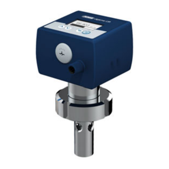
3 Device Description Device setup JUMO digiLine electronics forCR-Sensors in device version with a separate sensor 1) JUMO digiLine electronics forCR-Sensors 2) USB interface 3) M12 plug connector, 8-pole for sensor connection 4) M12 plug connector for output/input signals or inter-... - Page 13 JUMO digiLine device frontsCR Device version with display and membrane keyboard Device version without display and membrane key- board 1) JUMO digiLine device frontCR with operating panel 1) JUMO digiLine device frontCR without operating pan- 2) Display 2) Status LED...
-
Page 14: Description
Description Device version RS485 interface for JUMO digiLine and Modbus RTU This interface is used to connect to the JUMO digiLine bus system of the JUMO AQUIS touch S/P or to a JUMO mTRON T with Modbus interface. The plug & play support for the JUMO digiLine electronics simplifies sensor startup considerably. After the JUMO AQUIS touch S/P is connected, the JUMO digiLine electronic components are configured au- tomatically and ready for use immediately. - Page 15 The JUMO DSM software (DSM stands for Digital Sensor Management) can be used to manage, cali- brate, and test JUMO digiLine electronics on the PC. In addition, it serves as a configuration tool for the JUMO digiLine electronics. The connection to the PC is made via the USB interface. The JUMO DSM software adds data from the memory of JUMO digiLine electronics to its sensor database.
- Page 16 3 Device Description...
-
Page 17: Identifying The Device Version
4 Identifying the device version Order details 4.1.1 Head transmitter (202763...) Basic type 202763 JUMO digiLine CR HT10 (head transmitter with sensor type JUMO BlackLine CR-EC) Basic type extension Digital operation, plastic housing (JUMO digiLine) Digital operation, plastic housing (IO-Link) Display without display... - Page 18 4 Identifying the device version Basic type 202764 JUMO digiLine CR HT20 (head transmitter with sensor type JUMO ecoLine CR-PVC) Basic type extension Digital operation, plastic housing (JUMO digiLine) Digital operation, plastic housing (IO-Link) Display without display With display Version...
- Page 19 4 Identifying the device version Basic type 202765 JUMO digiLine CR HT30 (head transmitter with sensor type JUMO tecLine CR-VA) Basic type extension Digital operation, plastic housing (JUMO digiLine) Digital operation, plastic housing (IO-Link) Display without display With display Version...
- Page 20 4 Identifying the device version Order code Order example 202765 0010 1003 (10) (11) JUMO...
- Page 21 4 Identifying the device version Basic type 202766 JUMO digiLine CR HT40 (head transmitter with sensor type JUMO tecLine CR-SL Basic type extension Digital operation, plastic housing (JUMO digiLine) Digital operation, plastic housing (IO-Link) Display without display With display Version...
- Page 22 4 Identifying the device version Basic type 202767 JUMO digiLine CR HT50 (head transmitter with sensor type JUMO tecLine CR-PK Basic type extension Digital operation, plastic housing (JUMO digiLine) Digital operation, plastic housing (IO-Link) Display without display With display Version...
- Page 23 4 Identifying the device version Basic type 202768 JUMO digiLine CR HT60 (head transmitter with sensor type JUMO tecLine CR-GT Basic type extension Digital operation, plastic housing (JUMO digiLine) Digital operation, plastic housing (IO-Link) Display without display With display Version...
- Page 24 4 Identifying the device version Basic type 202769 JUMO digiLine CR HT70 (head transmitter with sensor type JUMO tecLine CR-4P Basic type extension Digital operation, plastic housing (JUMO digiLine) Digital operation, plastic housing (IO-Link) Display without display With display Version...
-
Page 25: Devices For Separate Sensors (202762)
4 Identifying the device version 4.1.2 Devices for separate sensors (202762) Basic type 202762 JUMO digiLine CR ST10 (for separate sensor) Basic type extension Digital operation, plastic housing (JUMO digiLine) Digital operation, plastic housing (IO-Link) Display without display With display... -
Page 26: Accessories
JUMO M12 connecting cable five-pole 0.5 m 00638312 JUMO Y-splitter 5-pole 00638327 JUMO digiLine hub 00646871 JUMO power supply unit for JUMO digiLine hub 00661597 JUMO M12 terminating connector 00461591 JUMO DSM software (Digital Sensor Management) 00655787 Sensor connection cable with M12 cable socket, 8-pole, with the ferrules at sensor end, 1.5 m... -
Page 27: Mounting
Aggressive gases and vapors have a negative effect on the operating life of the device. Dimensions 5.2.1 Device versions with separate sensor Dimensions of the JUMO digiLine electronic components... - Page 28 5 Mounting Dimensions of the mounting plate for wall, pipe and DIN rail mounting 63.3 29.8...
-
Page 29: Device Versions As Head Transmitter
5 Mounting 5.2.2 Device versions as head transmitter Dimensions of the JUMO digiLine electronic components... - Page 30 5 Mounting JUMO digiLine CR head transmitter Process connection 687, PVC: Stepped collar PVC DN25 Process connection Process connection 44.5 44.5 PVC body material PVC body material Stainless steel sensor Stainless steel sensor JUMO digiLine CR head transmitter JUMO digiLine CR head transmitter...
-
Page 31: Mounting Devices With A Separate Sensor
5 Mounting Mounting devices with a separate sensor Wall mounting (1) Wall/mounting surface (2) Mounting plate included in the scope of delivery of the JUMO digiLine CR (3) JUMO digiLine CR DIN-rail mounting (1) DIN rail (2) Mounting plate included in the scope of delivery of the JUMO digiLine CR... -
Page 32: Mounting Of Head Transmitters
(1) JUMO digiLine CR (2) Mounting plate from the scope of delivery of the JUMO digiLine CR with installed cable ties (3) Pipe/mast (at customer's site); cable ties are not included in the scope of delivery of the device. -
Page 33: Electrical Connection
Installation notes CAUTION! Disconnecting the JUMO digiLine bus line and/or removing the terminating resistors and termi- nating connectors during operation will disrupt the digiLine bus. Possible consequences include bus disruptions with loss of the measured values from the sensor on the bus affected. -
Page 34: Connection Diagram
0.5 Nm. The pin assignment shown here is intended primarily to provide an overview and serve as an aid when troubleshooting. Wiring work is required when connecting to the serial interface of a JUMO AQUIS touch S/P or JUMO mTRON T with the JUMO M12-digiLine master connecting cable ... - Page 35 6 Electrical connection Sensor connection A connecting cable with wire end ferrules on the sensor end is available for the JUMO digiLine CR in device versions with a separate sensor (see accessories). This cable must be provided with a cable socket suitable for the selected sensor and connected in accordance with the following table.
-
Page 36: Galvanic Isolation
6 Electrical connection 6.2.1 Galvanic isolation JUMO digiLine CR with RS485 interface (JUMO digiLine and Modbus) Probe section JUMO digiLine electronics Data Voltage supply DC 5 V / DC 24 V DC 50 V AC 30 V USB interface DC 5 V... -
Page 37: Connection Examples
JUMO digiLine pH/ORP/T and JUMO digiLine CR connected to a JUMO AQUIS touch S. The bus subscribers on the JUMO digiLine bus are connected to one another via a JUMO digiLine hub and M12 connecting cables. Appropriate fittings are available from JUMO for mounting the sensors. - Page 38 1 conductivity sensor with JUMO digiLine CR in the device version with RS485 interface on a JUMO mTRON T as Modbus master. Up to 31 digital sensors per RS485 interface can be integrat- ed. Optionally, a JUMO mTRON T central processing unit can be equipped with up to 2 RS485 interfaces (see order data for JUMO mTRON T).
- Page 39 6 Electrical connection Wiring diagram for Modbus mode Modbus master RS485 DC 5 V DC 5 V + (Pin 1) DC 24 V + (Pin 2) GND (Pin 3) DC 24 V A, RxD/TxD+ (Pin 5) B, RxD/TxD- (Pin 4)
- Page 40 6 Electrical connection...
-
Page 41: Operation
Configuration and calibration via interfaces All device versions can be connected to a PC via USB, and configured and calibrated using the JUMO DSM software. Refer to the operating manual for the JUMO DSM software for more details. -
Page 42: Device Menu
The user logs on and out here. In addition, passwords can be changed here. chapter 7.2.1 "Log-on/Log-out", page 43 Calibration Functions for calibrating the JUMO digiLineCRwith the currently connected sensor chapter 7.2.2 "Calibration", page 43 Device informa- Information on device hardware and software. -
Page 43: Log-On/Log-Out
7 Operation 7.2.1 Log-on/Log-out You can log on to the device in the "Log-on/Log-out" submenu. Depending on the rights required, this is necessary to change device settings and to perform calibrations. When you are logged in, the logged-in user is shown in the header of the measurement display. In addition, you can log out again or change passwords in the "Log-on/Log-out"... -
Page 44: Device Information
Sensor tag: ID for assigning JUMO digiLine electronics to a specific input for digital sensors of a specific master (JUMO AQUIS touch S/P) in your system. Linking of the JUMO digiLine electronics requires that the sensor tag of the input and JUMO digiLine electronics match. The sensor tag is es- tablished by the user. -
Page 45: Startup
Startup 8 Startup General information Startup of the JUMO digiLine CR with RS485 interface in the 2 possible versions is described below: • Sensor with JUMO digiLine electronics on a JUMO AQUIS touch S/P • Sensor with JUMO digiLine electronics on a Modbus master CAUTION! The electrical characteristics of analysis sensors are dependent upon numerous factors, e.g. -
Page 46: Functional Test
Startup with a JUMO mTRON T as the Modbus master A JUMO mTRON T has no plug & play mechanisms. The settings of the digital interface of the JUMO digiLine electronics must be made prior to connection with the JUMO DSM software in accordance with the interface settings of the Modbus master. -
Page 47: Calibration
(e. g. as the result of equipment modification) Each successfully completed calibration of the relative cell constant and TC calibration is recorded in the calibration logbook. The calibration logbook can be viewed on the PC using the JUMO DSM software. Calibration methods for CR conductivity sensors (conductive) Rel. - Page 48 9 Calibration temperature coefficient for each interval. This requires installation of a temperature sensor that the de- vice can use to sense the temperature of the sample solution. The series of temperature values consists of 7 values in total: • "Starting temperature and end temperature of the TC-curve"...
-
Page 49: Calibration Default Settings
Conductivity sensors with JUMO digiLine electronics can be calibrated using the JUMO DSM software on the PC in the case of device versions with an RS485 interface, via the operating panel of the JUMO AQUIS touch S/P or via local operation in the case of a device versions with a display. The calibration values are calculated in the JUMO digiLine electronics of the sensor. - Page 50 9 Calibration Calibrating the relative cell constant NOTE! Depending on the mode set for the relative cell constant in the configuration of the conductivity input, either a common relative cell constant is used for all 4 measuring ranges or a relative cell constant is determined separately for each measuring range ...
-
Page 51: Calibration Logbook
After a connection to the digital sensor has been estab- lished successfully by the JUMO DSM software, the calibration logbook entries in the digital sensor con- nected to the PC are read by the JUMO DSM software and saved on the PC. There is no limit to the... -
Page 52: Evaluation Criteria For Calibration
Sensor replacement counter reading (to assign the calibration logbook entries to the individual sen- sors in the sensor replacement history of the JUMO digiLine electronics) The calibration logbook can be viewed on the JUMO AQUIS touch S/P and on the PC using the JUMO DSM software. -
Page 53: Troubleshooting In The Event Of Faults
JUMO digiLine electronics which have been disconnected from the bus can be identified within the "Reference table" for the device software of the the JUMO AQUIS touch S/P. Further information in this regard can be found in the operating manual of the re- spective device. - Page 54 10 Troubleshooting in the event of faults...
-
Page 55: Data Overview
Information about the device and its process/operating data is stored in the JUMO digiLINE electronics. These data can be viewed on the JUMO AQUIS touch S/P or using the JUMO DSM software. The operating data includes signals such as alarms, measured values and sensor monitoring data. The measured values can be displayed and the status of sensor operation observed using the JUMO DSM software or on the JUMO AQUIS touch S/P. -
Page 56: Process Values
TAG number The "TAG number" identifies the measuring point with a unique ID assigned by the user using the JUMO DSM software. With the aid of the "TAG num- ber", the JUMO digiLine electronics can be assigned to a designated digital sensor input of a JUMO AQUIS touch S/P. -
Page 57: Operating Data
On reaching the maximum number of CIP or SIP cycles set for this pre-alarm signal, this pre-alarm is triggered and generates a corresponding signal on the JUMO AQUIS touch S/P. It can also be queried by a Modbus master (JU- MO mTRON T). -
Page 58: Calibration Data
The calibration alarm is triggered when the time set on the calibration timer has elapsed and generates a corresponding signal on the JUMO AQUIS touch S/P. It can also be queried by a Modbus master (JUMO mTRON T). On device versions with a display, the calibration alarm flashes in the header of... -
Page 59: Configuration
In addition, sensors with JUMO digiLine electronics in device versions with an RS485 interface can also be configured from a JUMO AQUIS touch S/P, or on a PC using the JUMO DSM software. Further infor- mation can be found in the operating manual and installation instructions of the JUMO AQUIS touch S/ P or the JUMO DSM software. -
Page 60: Measuring Ranges 1 To 4 For The Cr Input
Measuring ranges 1 to 4 for the CR input Measuring range selection On device versions with an RS485 interface for JUMO digiLine, the individual measuring ranges are ac- tivated by the master (JUMO AQUIS touch S/P). The master must be configured appropriately by the user (see documentation for JUMO AQUIS touch S/P). -
Page 61: Temperature Input
The linearization table for the measuring range concerned can be activated/deactivated with this parameter. Linearization ta- bles for JUMO digiLineCRcontain up to 30 value pairs in any measurement characteristic line. Each value pair assigns a dis- play value (Y-column) to a measured value (X-column). A linear- ization table is available for every measuring range. -
Page 62: Digital Interface
Ensure that interface settings are not changed inadvertently when using the JUMO DSM software. For operation on the JUMO mTRON T, the settings must be made in advance with the JUMO DSM soft- ware. Configuration item... -
Page 63: Calibration Timer
Time from one calibration to the next. The time at which a cali- bration is due is indicated by the calibration alarm on device ver- sions with a display. In addition, the calibration alarm is displayed on the JUMO AQUIS touch S/P. 12.7... - Page 64 12 Configuration Configuration item Selection/setting op- Explanation tion Sig. sec. value No signal Signal source for the secondary value display Temperature input In the measuring mode, the secondary value is shown on the Compensation temp. display as an additional value accompanying the main value Uncomp.
-
Page 65: Operation, Maintenance And Care
On device versions with a separate sensor, the sensor can be disconnected from the JUMO digiLine electronics. If the sensor needs to be replaced, the JUMO digiLine electronics can be connected to a new sensor and re-inserted. The "Sensor replacement function" must be used in this case to reset the corresponding data in the JUMO digiLine electronics and increment the "sensor counter". -
Page 66: Sensor Replacement While The Digiline Mode Is Active
If an individual sensor with JUMO digiLine electronics is replaced with a new sensor of the same kind, it is linked automatically and assigned in the JUMO AQUIS touch S/P to the previous function of the re- moved sensor. When several sensors are being replaced, it is necessary to ensure that multiple sensors with JUMO digiLine electronics are not disconnected from the bus at the same time. -
Page 67: Technical Data
The JUMO digiLine protocol assigns the interface parameters automatically during startup (Plug & Play). The Modbus RTU protocol is used to operate the JUMO digiLine electronics on a JUMO mTRON T CPU. For op- eration on a JUMO mTRON T, the interface parameters must be set prior to initial commissioning with the JUMO DSM software. -
Page 68: Electrical Data
Protection rating Protection rating III The voltage supply for the JUMO digiLine electronics must be provided with SELV or PELV and must meet the re- quirements for energy-limited electrical circuits to DIN EN 61010-1. The power supply current must be limited to 3 A. If the voltage supply allows higher current consumption, a fuse must be provided. -
Page 69: Environmental Influences
14 Technical data 14.5 Environmental influences 14.5.1 Device version as head transmitter Ambient temperature -20 to +60 °C Storage temperature -25 to +80 °C Shock resistance DIN EN 60654-3 Acceleration 40 m/s Duration Duration 5 ms Vibration resistance IEC 61298-3 Frequency range 10 to 1000 Hz Deflection... -
Page 70: Sensor Properties In Head Transmitters
The technical data for each of the sensors for the individual device versions, which are combined with the head transmitter, must be obtained from their data sheets. The relevant sensor types for the individ- ual device versions of the JUMO digiLine CR can be obtained from the following table. JUMO digiLine CR device versions... - Page 72 JUMO GmbH & Co. KG JUMO Instrument Co. Ltd. JUMO Process Control, Inc. Street address: JUMO House 6733 Myers Road Moritz-Juchheim-Straße 1 Temple Bank, Riverway East Syracuse, NY 13057, USA 36039 Fulda, Germany Harlow, Essex, CM20 2DY, UK Delivery address:...
Need help?
Do you have a question about the digiLine CR and is the answer not in the manual?
Questions and answers