Rigol DS1000Z-E Series User Manual
Digital
Hide thumbs
Also See for DS1000Z-E Series:
- Performance verification manual (26 pages) ,
- Service manual (24 pages) ,
- User manual (224 pages)

Related Manuals for Rigol DS1000Z-E Series


Summary of Contents for Rigol DS1000Z-E Series
- Page 1 User Guide DS1000Z-E Series Digital Oscilloscope Sept. 2019 RIGOL (SUZHOU) TECHNOLOGIES INC. GlobalTestSupply www. .com Find Quality Products Online at: sales@GlobalTestSupply.com...
- Page 2 Notices RIGOL products are covered by P.R.C. and foreign patents, issued and pending. RIGOL reserves the right to modify or change parts of or all the specifications and pricing policies at the company’s sole decision. Information in this publication replaces all previously released materials.
-
Page 3: Safety Requirement
RIGOL Safety Requirement General Safety Summary Please review the following safety precautions carefully before putting the instrument into operation so as to avoid any personal injury or damage to the instrument and any product connected to it. To prevent potential hazards, please follow the instructions specified in this manual to use the instrument properly. - Page 4 Do Not Operate With Suspected Failures. If you suspect that any damage may occur to the instrument, have it inspected by RIGOL authorized personnel before further operations. Any maintenance, adjustment or replacement especially to circuits or accessories must be performed by RIGOL authorized personnel.
-
Page 5: Safety Notices And Symbols
RIGOL Safety Notices and Symbols Safety Notices in this Manual: WARNING Indicates a potentially hazardous situation or practice which, if not avoided, will result in serious injury or death. CAUTION Indicates a potentially hazardous situation or practice which, if not avoided, could result in damage to the product or loss of important data. -
Page 6: Measurement Category
RIGOL Measurement Category Measurement Category DS1000Z-E series digital oscilloscopes can make measurements in Measurement Category I. WARNING This oscilloscope can only be used for measurements within its specified measurement categories. Measurement Category Definitions Measurement category I is for measurements performed on circuits not directly connected to MAINS. -
Page 7: Ventilation Requirement
RIGOL Ventilation Requirement This oscilloscope uses fan to force cooling. Please make sure that the air intake and exhaust areas are free from obstructions and have free air. When using the oscilloscope in a bench-top or rack setting, provide at least 10 cm clearance beside, above and behind the instrument for adequate ventilation. -
Page 8: Working Environment
RIGOL Working Environment Temperature Operating: 0℃ to +50℃ Non-operating: -40℃ to +70℃ Humidity 0℃ to +30℃: ≤95% relative humidity +30℃ to +40℃: ≤75% relative humidity +40℃ to +50℃: ≤45% relative humidity WARNING To avoid short circuits inside the instrument or electric shocks, please do not operate in humid environment. - Page 9 RIGOL Pollution degree 2: Normally only dry, non-conductive pollution occurs. Occasionally a temporary conductivity caused by condensation may occur. For example, general indoor environment. Pollution degree 3: Conductive pollution occurs, or dry, non-conductive pollution occurs which becomes conductive due to condensation which is expected. For example, sheltered outdoor environment.
-
Page 10: Care And Cleaning
RIGOL Care and Cleaning Care Do not store or leave the instrument where it may be exposed to direct sunlight for long periods of time. Cleaning Clean the instrument regularly according to its operating conditions. Disconnect the instrument from all power sources. -
Page 11: Ds1000Z-E Series Overview
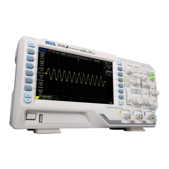
DS1000Z-E Series Overview DS1000Z-E series is a multifunctional and high-performance digital oscilloscope designed on the basis of the UltraVision technique developed by RIGOL. Featuring extremely high memory depth, wide dynamic range, clear display, excellent waveform capture rate and comprehensive triggering functions, it is a useful commissioning instrument for various fields such as communication, aerospace, defense, embedded systems, computers, research and education. -
Page 12: Document Overview
RIGOL Document Overview Main Topics of this Manual: Chapter 1 Quick Start Introduce the preparations before using the oscilloscope and provide a basic introduction of the instrument. Chapter 2 To Set the Vertical System Introduce the vertical system functions of the oscilloscope. - Page 13 POSITION Trigger Level Knob TRIGGER LEVEL Content Conventions in this Manual: DS1000Z-E series includes the following models. Unless otherwise noted, this manual takes DS1202Z-E for example to illustrate the functions and operation methods of DS1000Z-E series. DS1000Z-E User Guide GlobalTestSupply www.
- Page 14 RIGOL Model Analog Bandwidth Number of Analog Channels DS1202Z-E 200 MHz DS1000Z-E User Guide XIII GlobalTestSupply www. .com Find Quality Products Online at: sales@GlobalTestSupply.com...
-
Page 15: Table Of Contents
Measurement Category ................V Ventilation Requirement ................VI Working Environment ................VII Care and Cleaning ................... IX Environmental Considerations ..............IX DS1000Z-E Series Overview ..............X Document Overview ................XI Chapter 1 Quick Start ................ 1-1 General Inspection ................. 1-2 Appearance and Dimensions .............. - Page 16 Contents RIGOL Channel Coupling .................. 2-2 Bandwidth Limit ..................2-3 Probe Ratio ................... 2-3 Waveform Invert ................... 2-4 Vertical Scale ..................2-4 Amplitude Unit ..................2-5 Channel Label ..................2-5 Delay Calibration of the Analog Channel ..........2-7 Chapter 3 To Set the Horizontal System ..........
- Page 17 Contents RIGOL I2C Trigger..................5-34 SPI Trigger ..................5-37 Trigger Output Connector..............5-39 Chapter 6 MATH and Measurement ............ 6-1 Math Operation ..................6-2 Addition ..................6-2 Subtraction ..................6-3 Multiplication ................... 6-4 Division ..................6-4 FFT ....................6-6 "AND" Operation ................6-11 "OR"...
- Page 18 Contents RIGOL Chapter 8 Reference Waveform ............8-1 To Enable REF Function................8-2 To Select REF Source ................8-2 To Adjust REF Waveform Display ............. 8-2 To Save to Internal Memory ..............8-2 To Set the Color ..................8-3 To Reset the Reference Waveform ............8-3 To Export to Internal or External Memory ..........
- Page 19 Contents RIGOL Sound ..................13-6 Language ..................13-6 System Information ............... 13-6 Vertical Reference ................13-6 Power-off Recall ................13-7 Self-calibration ................13-7 Print Setting .................. 13-8 Aux Output ................. 13-10 Option Management ..............13-11 Auto Options ................13-12 Key Lock ..................13-12 Chapter 14 Remote Control ............
-
Page 20: Chapter 1 Quick Start
Chapter 1 Quick Start RIGOL Chapter 1 Quick Start This chapter introduces the precautions when using the oscilloscope for the first time, the front/rear panels of the oscilloscope, the user interface and the using method of the built-in help system. -
Page 21: General Inspection
The consigner or carrier shall be liable for the damage to the instrument resulting from shipment. RIGOL would not be responsible for free maintenance/rework or replacement of the instrument. 2. Inspect the instrument... -
Page 22: Appearance And Dimensions
Chapter 1 Quick Start RIGOL Appearance and Dimensions Figure 1-1 Front View Unit: mm Figure 1-2 Top View Unit: mm DS1000Z-E User Guide GlobalTestSupply www. .com Find Quality Products Online at: sales@GlobalTestSupply.com... -
Page 23: To Prepare The Oscilloscope For Use
Chapter 1 Quick Start RIGOL To Prepare the Oscilloscope for Use To Adjust the Supporting Legs Adjust the supporting legs properly to use them as stands to tilt the oscilloscope upwards for stable placement of the oscilloscope as well as better operation and observation. -
Page 24: Turn-On Checkout
From this dialog box you can view the name, detail, version and remaining trial time of the option currently installed. To Connect the Probe RIGOL provides passive probe for DS1000Z-E series. For the model of the probes, DS1000Z-E Series Datasheet please refer to . -
Page 25: Function Inspection
Chapter 1 Quick Start RIGOL Function Inspection Press Storage Default to restore the oscilloscope to its default configuration. Connect the ground alligator clip of the probe to the "Ground Terminal" as shown in the figure below. Use the probe to connect the input terminal of CH1 of the oscilloscope and the "Compensation Signal Output Terminal"... - Page 26 Chapter 1 Quick Start RIGOL The signal output from the probe compensation connector can only be used for probe compensation adjustment and cannot be used for calibration. DS1000Z-E User Guide GlobalTestSupply www. .com Find Quality Products Online at: sales@GlobalTestSupply.com...
-
Page 27: Probe Compensation
Chapter 1 Quick Start RIGOL Probe Compensation When the probes are used for the first time, you should compensate the probes to make them match the input channels of the oscilloscope. Non-compensated or poorly compensated probes may cause measurement inaccuracy or errors. The probe compensation procedures are as follows. -
Page 28: Front Panel Overview
Chapter 1 Quick Start RIGOL Front Panel Overview 9 10 11 12 15 16 17 18 Figure 1-9 Front Panel Overview Table 1-1 Front Panel Descriptions Description Description Measurement Menu Softkeys Help/Print Power Key Function Menu Softkeys USB Host Interface... -
Page 29: Rear Panel Overview
Chapter 1 Quick Start RIGOL Rear Panel Overview Figure 1-10 Rear Panel Overview 1. Handle Pull up the handle vertically for easy carry of the instrument. When you do not need the handle, press it down. 2. LAN Connect the instrument to network via this interface for remote control. This oscilloscope conforms to the LXI CORE 2011 DEVICE class instrument standards and can quickly build test system with other instruments. - Page 30 Chapter 1 Quick Start RIGOL Pass/Fail: The instrument can output a negative pulse via this connector when a failed waveform is detected during the pass/fail test. The instrument continuously outputs a low level via this connector when no failed waveform is detected.
-
Page 31: Front Panel Function Overview
Chapter 1 Quick Start RIGOL Front Panel Function Overview VERTICAL CH1, CH2: analog channel setting keys. The 2 channels are marked by different colors which are also used to mark both the corresponding waveforms on the screen and the channel input connectors. -
Page 32: Horizontal
Chapter 1 Quick Start RIGOL HORIZONTAL HORIZONTAL POSITION: modify the horizontal position. The trigger point would move left or right relative to the center of the screen when you rotate the knob. During the modification, waveforms of all the channels would move left or right and the horizontal position message (e.g. -
Page 33: Trigger
Chapter 1 Quick Start RIGOL TRIGGER MODE: press this key to switch the trigger mode to Auto, Normal or Single and the corresponding state backlight of the current trigger mode would be illuminated. TRIGGER LEVEL: modify the trigger level. Turn clockwise to increase the level and turn counterclockwise to reduce the level. -
Page 34: Run/Stop
Chapter 1 Quick Start RIGOL RUN/STOP Press this key to "RUN" or "STOP" waveform sampling. In the "RUN" state, the key is illuminated in yellow. In the "STOP" state, the key is illuminated in red. SINGLE Press this key to set the trigger mode to "Single". In single trigger mode, press FORCE to generate a trigger signal immediately. -
Page 35: Function Menus
Chapter 1 Quick Start RIGOL Function Menus Measure: press this key to open the measurement setting menu. You can set the measurement source, turn on or off the frequency counter, all measure, statistic function and etc. Press MENU at the left of the screen to open the measurement menus of 37 waveform parameters. -
Page 36: Print
Chapter 1 Quick Start RIGOL Print Press this key to print the screen or save the screen to a USB storage device. ― If a PictBridge printer is connected currently and the printer is in idle state, pressing this key will execute the print operation. -
Page 37: User Interface
Chapter 1 Quick Start RIGOL User Interface DS1000Z-E provides 7.0 inch WVGA (800*480) TFT LCD. Figure 1-11 User Interface 1. Auto Measurement Items Provide 20 horizontal (HORIZONTAL) and 17 vertical (VERTICAL) measurement parameters. Press the softkey at the left of the screen to activate the corresponding measurement item. - Page 38 Chapter 1 Quick Start RIGOL horizontal time base. 5. Waveform Memory Provide the schematic diagram of the memory position of the waveform currently on the screen. waveform in the memory waveform on the screen 6. Trigger Position Display the trigger position of the waveform in the waveform memory and on the screen.
- Page 39 Chapter 1 Quick Start RIGOL 12. Analog Channel Label/Waveform Different channels are marked with different colors and the colors of the channel label and waveform are the same. 13. CH2 Vertical Scale Display the voltage value per grid of CH2 waveform vertically.
-
Page 40: Parameter Setting Method
Chapter 1 Quick Start RIGOL Parameter Setting Method DS1000Z-E supports the following two parameter setting methods. Method one: For the parameters with displayed on the menu, you can turn the multifunction knob directly to set the desired values. Method two:... -
Page 41: To Use The Security Lock
Chapter 1 Quick Start RIGOL To Use the Security Lock If needed, you can use the security lock (please buy it yourself) to lock the oscilloscope to a fixed location. The method is as follows, align the lock with the lock hole and plug it into the lock hole vertically, turn the key clockwise to lock the oscilloscope and then pull the key out. -
Page 42: To Use The Built-In Help System
Chapter 1 Quick Start RIGOL To Use the Built-in Help System The help system of this oscilloscope provides instructions for all the function keys (including the menu keys) on the front panel. Press Help to open the help interface and press again to close the interface. The help interface mainly consists of two parts. -
Page 43: Chapter 2 To Set The Vertical System
Chapter 2 To Set the Vertical System RIGOL Chapter 2 To Set the Vertical System The contents of this chapter: To Enable the Analog Channel Channel Coupling Bandwidth Limit Probe Ratio Waveform Invert Vertical Scale ... -
Page 44: To Enable The Analog Channel
Chapter 2 To Set the Vertical System RIGOL To Enable the Analog Channel DS1000Z-E provides 2 analog input channels (CH1 and CH2). As the setting methods of the vertical systems of the two channels are the same, this chapter takes CH1 as an example to illustrate the setting method of the vertical system. -
Page 45: Bandwidth Limit
Chapter 2 To Set the Vertical System RIGOL Bandwidth Limit DS1000Z-E supports the bandwidth limit function which can reduce the display noise. For example, the signal under test is a pulse with high frequency oscillation. When the bandwidth limit is disabled, the high frequency components of the ... -
Page 46: Waveform Invert
Chapter 2 To Set the Vertical System RIGOL Waveform Invert Press CH1 Invert to turn on or off waveform invert. When waveform invert is turned off, the waveform display is normal; when waveform invert is turned on, the waveform voltage values are inverted (as shown in the figures below). -
Page 47: Amplitude Unit
Chapter 2 To Set the Vertical System RIGOL and "Fine" adjustments. When changing the vertical scale of the analog channel by rotating VERTICAL SCALE, you can select to expand or compress the waveform around the "Center" or "Ground". For more details, please refer to the introduction in "Vertical Reference". - Page 48 Chapter 2 To Set the Vertical System RIGOL Select "A " using and press down to switch it to " A". Select "C" using and press down to input the character. Use the same method to input "hn1". After finishing the input, press OK to finish the editing. If the Display is enabled, the label will be displayed at the left of CH1 waveform.
-
Page 49: Delay Calibration Of The Analog Channel
Chapter 2 To Set the Vertical System RIGOL Delay Calibration of the Analog Channel When using an oscilloscope for actual measurement, the transmission delay of the probe cable may bring relatively greater error (zero offset). DS1000Z-E supports user to set a delay time to calibrate the zero offset of the corresponding channel. Zero offset is defined as the offset of the crossing point of the waveform and trigger level line relative to the trigger position, as shown in the figure below. -
Page 50: Chapter 3 To Set The Horizontal System
Chapter 3 To Set the Horizontal System RIGOL Chapter 3 To Set the Horizontal System The contents of this chapter: Delayed Sweep Time Base Mode DS1000Z-E User Guide GlobalTestSupply www. .com Find Quality Products Online at: sales@GlobalTestSupply.com... -
Page 51: Delayed Sweep
Chapter 3 To Set the Horizontal System RIGOL Delayed Sweep Delayed sweep can be used to enlarge a length of waveform horizontally to view waveform details. Press MENU in the horizontal control area (HORIZONTAL) on the front panel and press Delayed to enable or disable delayed sweep. -
Page 52: Time Base Mode
Chapter 3 To Set the Horizontal System RIGOL You can also press down HORIZONTAL SCALE (delayed sweep shortcut key) to directly switch to the delayed sweep mode. Time Base Mode Press MENU in the horizontal control area (HORIZONTAL) on the front panel and then press Time Base to select the time base mode of the oscilloscope. - Page 53 Chapter 3 To Set the Horizontal System RIGOL According to sin=A/B or C/D (wherein, is the phase deviation angle between the two channels and the definitions of A, B, C and D are as shown in the figure above), the phase deviation angle is obtained, that is: =arcsin (A/B) or arcsin (C/D)
-
Page 54: Roll Mode
Chapter 3 To Set the Horizontal System RIGOL Note: The maximum sample rate of XY mode is 500 MSa/s. Generally, longer sample waveform can ensure better display effect of Lissajous figure. But due to the limitation of the memory depth, you have to reduce the waveform sample rate to acquire longer waveform (refer to the introduction in "Memory Depth"). -
Page 55: Chapter 4 To Set The Sample System
Chapter 4 To Set the Sample System RIGOL Chapter 4 To Set the Sample System The contents of this chapter: Acquisition Mode Sin(x)/x Sample Rate Memory Depth Anti-aliasing DS1000Z-E User Guide GlobalTestSupply www. .com Find Quality Products Online at:... -
Page 56: Acquisition Mode
Chapter 4 To Set the Sample System RIGOL Acquisition Mode The acquisition mode is used to control how to generate waveform points from sample points. Press Acquire Mode on the front panel and use to select the desired acquisition mode (the default is normal), then press down the knob to select this mode. -
Page 57: High Resolution
Chapter 4 To Set the Sample System RIGOL Figure 4-1 The Waveform before Average Figure 4-2 The Waveform after 256 Averages High Resolution This mode uses a kind of ultra-sample technique to average the neighboring points of the sample waveform to reduce the random noise on the input signal and generate much smoother waveforms on the screen. -
Page 58: Sin(X)/X
Chapter 4 To Set the Sample System RIGOL Sin(x)/x Press Sin(x)/x to enable or disable the dynamic sine interpolation function which can acquire better restoration of the original waveform. Note: If the number of channels currently turned on is less than three, Sin(x)/x is grayed out and disabled. - Page 59 Chapter 4 To Set the Sample System RIGOL 3. Waveform Leakage: when the sample rate is too low, the waveform rebuilt from the sample data does not reflect all the actual signal information. Pulse disappeared DS1000Z-E User Guide GlobalTestSupply www.
-
Page 60: Memory Depth
Chapter 4 To Set the Sample System RIGOL Memory Depth Memory depth refers to the number of waveform points that the oscilloscope can store in a single trigger sample and it reflects the storage ability of the sample memory. DS1000Z-E provides up to 24 Mpts standard memory depth. -
Page 61: Anti-Aliasing
Chapter 4 To Set the Sample System RIGOL Anti-aliasing At slower sweep speed, the sample rate is reduced and a dedicated display algorithm can be used to minimize the possibility of aliasing. Press Acquire Anti-aliasing to enable or disable the anti-aliasing function. By default, anti-aliasing is disabled and waveform aliasing is more possible. -
Page 62: Chapter 5 To Trigger The Oscilloscope
Chapter 5 To Trigger the Oscilloscope RIGOL Chapter 5 To Trigger the Oscilloscope As for trigger, you set certain trigger condition according to the requirement and when a waveform in the waveform stream meets this condition, the oscilloscope captures this waveform as well as the neighbouring part and displays them on the screen. -
Page 63: Trigger Source
Chapter 5 To Trigger the Oscilloscope RIGOL Trigger Source Press MENU Source in the trigger control area (TRIGGER) on the front panel to select the desired trigger source. Analog channels CH1 and CH2, EXT (external trigger), or the AC Line can all be used as trigger source. -
Page 64: Trigger Mode
Chapter 5 To Trigger the Oscilloscope RIGOL Trigger Mode The following is the schematic diagram of the acquisition memory. To easily understand the trigger event, the acquisition memory is divided into the pre-trigger buffer and post-trigger buffer. Trigger Event Pre-trigger Buffer... -
Page 65: Trigger Coupling
Chapter 5 To Trigger the Oscilloscope RIGOL Trigger Coupling Trigger coupling decides which kind of components will be transmitted to the trigger module. Please distinguish it from "Channel Coupling". DC: allow DC and AC components into the trigger path. ... -
Page 66: Trigger Holdoff
Chapter 5 To Trigger the Oscilloscope RIGOL Trigger Holdoff Trigger holdoff can be used to stably trigger complex waveforms (such as modulated waveform). Holdoff time is the amount of time that the oscilloscope waits for re-arming the trigger module after generating a correct trigger. The oscilloscope will not trigger even if the trigger condition is met during the holdoff time and will only re-arm the trigger module after the holdoff time expires. -
Page 67: Trigger Type
Chapter 5 To Trigger the Oscilloscope RIGOL Trigger Type DS1000Z-E provides various trigger functions. Among various trigger types, RS232 trigger, I2C trigger and SPI trigger are serial bus triggers. Edge Trigger Pulse Trigger Slope Trigger Video Trigger ... -
Page 68: Edge Trigger
Chapter 5 To Trigger the Oscilloscope RIGOL Edge Trigger Trigger on the trigger threshold of the specified edge of the input signal. Trigger Type: Press Type, rotate to select "Edge" and press down . At this point, the trigger setting information is displayed at the upper right corner of the screen. -
Page 69: Pulse Trigger
Chapter 5 To Trigger the Oscilloscope RIGOL Pulse Trigger Trigger on the positive or negative pulse with a specified width. In this mode, the oscilloscope will trigger when the pulse width of the input signal satisfies the specified pulse width condition. - Page 70 Chapter 5 To Trigger the Oscilloscope RIGOL of pulse width. : trigger when the negative pulse width of the input signal is greater than the specified pulse width. : trigger when the negative pulse width of the input signal is lower than ...
-
Page 71: Slope Trigger
Chapter 5 To Trigger the Oscilloscope RIGOL Slope Trigger In slope trigger, the oscilloscope triggers on the positive or negative slope of the specified time. This trigger mode is applicable to ramp and triangle waveforms. Trigger Type: Press Type, rotate to select "Slope"... - Page 72 Chapter 5 To Trigger the Oscilloscope RIGOL : trigger when the negative slope time of the input signal is greater than the specified lower limit of time and lower than the specified upper limit of time. Time Setting: When the Slope Condition is set to ...
- Page 73 Chapter 5 To Trigger the Oscilloscope RIGOL Figure 5-5 Trigger Level Information Display Note: Under the "Slope" trigger menu, you can also press down the trigger level knob continuously to switch the vertical window. During the adjustment of trigger level, two orange trigger level lines and two trigger...
-
Page 74: Video Trigger
Chapter 5 To Trigger the Oscilloscope RIGOL Video Trigger The video signal can include image information and timing information and can adopt different standards and formats. DS1000Z-E can trigger on the standard video signal field or line of NTSC (National Television Standards Committee), PAL (Phase Alternating Line) or SECAM (Sequential Couleur A Memoire). - Page 75 In the trigger debugging process of video signals, the frequency in different part of the signal can be reflected by different brightness as RIGOL digital oscilloscope provides the intensity graded color display function. Experienced users can quickly judge the signal quality and discover abnormalities.
-
Page 76: Pattern Trigger
Chapter 5 To Trigger the Oscilloscope RIGOL Pattern Trigger Identify a trigger condition by looking for a specified pattern. This pattern is a logical "AND" combination of channels. Each channel can have a value of high (H), low (L) or don't care (X). A rising or falling edge (you can only specify a single edge) can be specified for one channel included in the pattern. - Page 77 Chapter 5 To Trigger the Oscilloscope RIGOL : set the pattern to the rising or falling edge of the channel selected. Note: Only one edge (rising or falling edge) can be specified in the pattern. If one edge item is currently defined and then another edge item is defined in another channel in the pattern, the former edge item defined will be replaced by X.
-
Page 78: Duration Trigger
Chapter 5 To Trigger the Oscilloscope RIGOL Duration Trigger In duration trigger, the instrument identifies a trigger condition by looking for the duration of a specified pattern. This pattern is a logical "AND" combination of the channels. Each channel can have a value of high (H), low (L) or don’t care (X). The instrument triggers when the duration (△T) of this pattern meets the preset time, as... - Page 79 Chapter 5 To Trigger the Oscilloscope RIGOL All Bits: Press AllBits to set the patterns of all trigger sources to the pattern settings selected currently. Trigger Condition: Press When to select the desired trigger condition. >: trigger when the duration of the pattern is greater than the preset time.
-
Page 80: Timeout Trigger
Chapter 5 To Trigger the Oscilloscope RIGOL TimeOut Trigger In timeout trigger, the instrument triggers when the time interval (△T) from when the rising edge (or falling edge) of the input signal passes through the trigger level to when the neighbouring falling edge (or rising edge) passes through the trigger level is greater than the timeout time set, as shown in the figure below. - Page 81 Chapter 5 To Trigger the Oscilloscope RIGOL ns to 10 s. Trigger Mode: Press Sweep to open the trigger mode list and select auto, normal or single. For the details, please refer to "Trigger Mode". The corresponding status light of the current trigger mode turns on.
-
Page 82: Runt Trigger
Chapter 5 To Trigger the Oscilloscope RIGOL Runt Trigger This trigger mode is used to trigger pulses that pass through one trigger level but fail to pass through the other trigger level as shown in the figure below. Positive Runt Pulse... - Page 83 Chapter 5 To Trigger the Oscilloscope RIGOL Limit to set the minimum pulse width of runt trigger and the range is from 8.00 ns to 9.99 s. Note: The lower limit of the pulse width must be lower than the upper limit.
-
Page 84: Window Trigger
Chapter 5 To Trigger the Oscilloscope RIGOL Window Trigger Window trigger provides a high trigger level and a low trigger level. The instrument triggers when the input signal passes through the high trigger level or the low trigger level. Trigger Type: Press Type, rotate to select "Window"... - Page 85 Chapter 5 To Trigger the Oscilloscope RIGOL Trigger Mode: Press Sweep to open the trigger mode list and select auto, normal or single. For the details, please refer to "Trigger Mode". The corresponding status light of the current trigger mode turns on.
-
Page 86: Delay Trigger
Chapter 5 To Trigger the Oscilloscope RIGOL Delay Trigger In delay trigger, you need to set signal source A and signal source B. The oscilloscope triggers when the time difference (△T) between the specified edges of source A (Edge A) and source B (Edge B) meets the preset time limit, as shown in the figure below. - Page 87 Chapter 5 To Trigger the Oscilloscope RIGOL Edge B: Press EdgeB to select the trigger edge type of signal source B in delay trigger. It can be set to the rising edge or falling edge. Delay Type: Press DelayType to set the time limit condition of delay trigger.
- Page 88 Chapter 5 To Trigger the Oscilloscope RIGOL TRIGGER LEVEL to modify the level. For the details, please refer to the introduction of "Trigger Level". DS1000Z-E User Guide 5-27 GlobalTestSupply www. .com Find Quality Products Online at: sales@GlobalTestSupply.com...
-
Page 89: Setup/Hold Trigger
Chapter 5 To Trigger the Oscilloscope RIGOL Setup/Hold Trigger In setup/hold trigger, you need to set the data signal line and clock signal line. The setup time starts when the data signal passes the trigger level and ends at the coming of the specified clock edge;... - Page 90 Chapter 5 To Trigger the Oscilloscope RIGOL Setup Type: It is used to select the different trigger types of setup/hold trigger. Press SetupType to select the desired setup type. Setup: the oscilloscope triggers when the setup time is less than the specified ...
-
Page 91: Nth Edge Trigger
Chapter 5 To Trigger the Oscilloscope RIGOL Nth Edge Trigger Trigger on the nth edge that appears after the specified idle time. For example, in the waveform shown in the figure below, the instrument should trigger on the second rising edge after the specified idle time (the time between two neighbouring rising edges) and the idle time should be set to P<Idle Time<M. - Page 92 Chapter 5 To Trigger the Oscilloscope RIGOL Idle Time: Press Idle to set the idle time before the edge counting in Nth edge trigger. The range available is from 16 ns to 10 s. Edge Number: Press Edge to set the value of "N" in Nth edge trigger and the range available is from 1 to 65535.
-
Page 93: Rs232 Trigger
1 bit start bit, 5~8 bits data bits, 1 bit check bit and 1~2 bits stop bit(s). Its format is as shown in the figure below. DS1000Z-E series oscilloscope triggers when the start frame, error frame, check error or the specified data of the RS232 signal is detected. - Page 94 Chapter 5 To Trigger the Oscilloscope RIGOL selected: --press Data Bits to select "5 bits", "6 bits", "7 bits" or "8 bits"; --press Data and use to set the data value of RS232 trigger. According to the setting in Data Bits and the ranges can be from 0 to 31, from 0 to 63, from 0 to 127 or from 0 to 255 respectively.
-
Page 95: I2C Trigger
Chapter 5 To Trigger the Oscilloscope RIGOL I2C Trigger I2C is a 2-wire serial bus used to connect the microcontroller and its peripheral device and is a bus standard widely used in the microelectronic communication control field. The I2C serial bus consists of SCL and SDA. Its transmission rate is determined by SCL and its transmission data is determined by SDA, as shown in the figure below. - Page 96 Chapter 5 To Trigger the Oscilloscope RIGOL MissedACK: trigger when the SDA data is high level during any acknowledgement of SCL clock position. Address: the trigger searches for the specified address value. When this event occurs, the oscilloscope will trigger on the read/write bit. After this trigger condition is selected: --press AddrBits to select "7 bits", "8 bits"...
- Page 97 Chapter 5 To Trigger the Oscilloscope RIGOL Trigger Setting: Press Setting to set the trigger parameter (noise rejection) under this trigger type. Trigger Level: When SCL is an analog channel, press SCL and use TRIGGER LEVEL to modify the trigger level of the SCL channel. When SDA is an analog channel, press SDA and use TRIGGER LEVEL to modify the trigger level of the SDA channel.
-
Page 98: Spi Trigger
Chapter 5 To Trigger the Oscilloscope RIGOL SPI Trigger In SPI trigger, after the CS or timeout condition is satisfied, the oscilloscope triggers when the specified data is found. When using SPI trigger, you need to specify the SCL clock sources and SDA data sources. Below is the sequential chart of SPI bus. - Page 99 Chapter 5 To Trigger the Oscilloscope RIGOL signal line. The available channels are CH1 or CH2 (only the channels currently enabled can be selected). For the details, please refer to the introduction in "Trigger Source". The current trigger source is displayed at the upper right corner of the screen.
-
Page 100: Trigger Output Connector
Chapter 5 To Trigger the Oscilloscope RIGOL Trigger Output Connector The trigger output connector ([Trigger Out]) on the rear panel can output trigger signals determined by the current setting. Trigger Output Connector A signal which reflects the current oscilloscope capture rate can be output from [Trigger Out] connector each time a trigger is generated by the oscilloscope. -
Page 101: Chapter 6 Math And Measurement
Chapter 6 MATH and Measurement RIGOL Chapter 6 MATH and Measurement DS1000Z-E can make math operation, cursor measurement and auto measurement after data is sampled and displayed. The contents of this chapter: Math Operation Auto Measurement Cursor Measurement ... -
Page 102: Math Operation
Chapter 6 MATH and Measurement RIGOL Math Operation DS1000Z-E can realize various math operations, including: Algebra operations: A+B, A-B, A× B and A/B Spectrum operation: FFT Logic operations: A&&B, A||B, A^B and !A Function operations: Intg, Diff, Sqrt, Lg, Ln, Exp and Abs ... -
Page 103: Subtraction
Chapter 6 MATH and Measurement RIGOL "Fx Operation"). Note: Smooth is grayed out and disabled. Smooth is only available for differential operation. You can also use HORIZONTAL POSITION and HORIZONTAL SCALE to adjust the horizontal position and scale of the operation results. -
Page 104: Multiplication
Chapter 6 MATH and Measurement RIGOL Multiplication Multiply the waveform voltage values of signal source A and B point by point and display the results. Press MATH Math Operator to select "A× B": Press Operation to enable or disable the multiplication operation function. - Page 105 Chapter 6 MATH and Measurement RIGOL Press SourceA and SourceB to select the desired channels (CH1, CH2, or fx (please refer to the introduction in "Fx Operation")). Press Offset and use to adjust the vertical position of the operation results.
-
Page 106: Fft
RIGOL FFT (Fast Fourier Transform) is used to transform time domain signals to frequency domain components (frequency spectrum). DS1000Z-E series oscilloscope provides FFT operation function which enables users to observe the time domain waveform and spectrum of the signal at the same time. FFT operation can facilitate the... - Page 107 Chapter 6 MATH and Measurement RIGOL waveform corresponding to the horizontal center of the screen. 4. Horizontal Scale Press Hz/Div and use to adjust the horizontal scale of the frequency domain waveform. 5. Vertical Position Press Offset and use to adjust the vertical position of the operation results.
- Page 108 Chapter 6 MATH and Measurement RIGOL Table 6-1 Window Function Waveforms Suitable for Window Characteristics Measurement Rectangle The best frequency Transient or short pulse, the signal levels resolution; before and after the multiplication are the poorest amplitude basically the same;...
- Page 109 Chapter 6 MATH and Measurement RIGOL Trigger Position 16384 points If the trigger position is in the memory and the number of the points from the trigger point to the end point of the memory is greater than or equal to 16384, the instrument will read the data of 16384 points from the trigger point.
- Page 110 Chapter 6 MATH and Measurement RIGOL Tips You can adjust the center frequency and horizontal scale at the same time using HORIZONTAL SCALE. Signals with DC components or deviation would cause error or deviation of the FFT waveform components. To reduce the DC components, set the "Channel Coupling"...
-
Page 111: And" Operation
Chapter 6 MATH and Measurement RIGOL "AND" Operation Perform logic "AND" operation on the waveform voltage values of the specified sources point by point and display the results. In operation, when the voltage value of the source channel is greater than the threshold of the corresponding channel, it is regarded as logic "1";... -
Page 112: Or" Operation
Chapter 6 MATH and Measurement RIGOL SCALE to adjust the horizontal position and scale of the operation results. "OR" Operation Perform logic "OR" operation on the waveform voltage values of the specified sources point by point and display the results. In operation, when the voltage value of the source channel is greater than the threshold of the corresponding channel, it is regarded as logic "1";... -
Page 113: Xor" Operation
Chapter 6 MATH and Measurement RIGOL Note: Smooth is grayed out and disabled. It is only available for differential operation. You can also use HORIZONTAL POSITION and HORIZONTAL SCALE to adjust the horizontal position and scale of the operation results. -
Page 114: Not" Operation
Chapter 6 MATH and Measurement RIGOL scale is enabled, the instrument will adjust the vertical scale of the operation results to the optimal value according to the current configuration. Note: Smooth is grayed out and disabled. It is only available for differential operation. -
Page 115: Intg
Chapter 6 MATH and Measurement RIGOL operation results to the optimal value according to the current configuration. Note: Smooth is grayed out and disabled. It is only available for differential operation. You can also use HORIZONTAL POSITION and HORIZONTAL ... -
Page 116: Diff
Chapter 6 MATH and Measurement RIGOL Diff Calculate the discrete time differentiate of the selected source. For example, you can use differentiate to calculate the instantaneous slope of a waveform. Press MATH Math Operator to select "Diff": Press Operation to enable or disable the "Diff" operation function. -
Page 117: Sqrt
Chapter 6 MATH and Measurement RIGOL Sqrt Calculate the square root of the selected source point by point and display the results. When the operation is invalid, "NAN" is displayed at the bottom of the screen. Press MATH Math Operator to select "Sqrt": Press Operation to enable or disable the "Sqrt"... - Page 118 Chapter 6 MATH and Measurement RIGOL Press Offset and use to adjust the vertical position of the operation results. Press Scale and use to adjust the vertical scale of the operation results. Press Scale Reset to adjust the vertical scale of the operation results to the ...
-
Page 119: Exp
Chapter 6 MATH and Measurement RIGOL ― Press Auto Scale to enable or disable the auto scale function. When auto scale is enabled, the instrument will adjust the vertical scale of the operation results to the optimal value according to the current configuration. -
Page 120: Abs
Chapter 6 MATH and Measurement RIGOL Calculate the absolute value of the selected source and display the results. Press MATH Math Operator to select "Abs": Press Operation to enable or disable the "Abs" operation function. Press Source to select the desired channel (CH1, CH2, or fx (please refer to the ... - Page 121 Chapter 6 MATH and Measurement RIGOL Press Scale Reset to adjust the vertical scale of the operation results to the optimal value according to the current configuration. Press Filter to select the desired filter type. : low pass, namely only the signals whose frequencies are lower ―...
-
Page 122: Fx Operation
Chapter 6 MATH and Measurement RIGOL Fx Operation DS1000Z-E supports the fx operation function which can achieve more complex operations. The procedures are as follows: Split the complex operation Users can split a more complex operation into inner and outer layers (the inner layer can only be one of the algebra operations;... -
Page 123: Auto Measurement
Chapter 6 MATH and Measurement RIGOL Auto Measurement DS1000Z-E provides auto measurements of 37 waveform parameters and the statistics and analysis of the measurement results. What’s more, you can also use the frequency counter to realize more precise frequency measurement. -
Page 124: One-Key Measurement Of 37 Parameters
Chapter 6 MATH and Measurement RIGOL One-key Measurement of 37 Parameters Press MENU at the left of the screen to turn on the measurement menu of the 37 parameters and then press the corresponding menu softkey to quickly realize "One-key" measurement. The measurement results can be displayed at the bottom of the screen in various font sizes (press Measure ... - Page 125 Chapter 6 MATH and Measurement RIGOL Time Parameters Fall Time Rise Time Threshold Upper Limit +Width -Width Threshold Middle Value Threshold Lower Limit Period Figure 6-3 Time Parameters 1. Period: defined as the time between the middle threshold points of two consecutive, like-polarity edges.
- Page 126 Chapter 6 MATH and Measurement RIGOL Count Values 1. +Pulses: the number of positive pulses that rise from below the threshold lower limit to above the threshold upper limit. +Pulses = n Threshold Upper Limit Threshold Lower Limit 2. -Pulses: the number of negative pulses that fall from above the threshold upper limit to below the threshold lower limit.
- Page 127 Chapter 6 MATH and Measurement RIGOL Delay and Phase Period Source1 Delay Source2 Figure 6-4 Delay and Phase Source 1 and source 2, the same as source A and source B in the measurement setting menu can be one of the channels (CH1-CH2). For the setting method, please refer to the introduction in "Measurement Setting".
- Page 128 Chapter 6 MATH and Measurement RIGOL Voltage Parameters Overshoot Vmax Vupper Vtop Vamp Vmid Vbase Vlower Vmin Preshoot Figure 6-5 Voltage Parameters 1. Vmax: the voltage value from the highest point of the waveform to the GND. 2. Vmin: the voltage value from the lowest point of the waveform to the GND.
- Page 129 Chapter 6 MATH and Measurement RIGOL 12. Per.Vrms: the root mean square value within a period. The calculation formula is as follows. (6-3) RMS = Wherein, is the measurement result of the th point, is the number of points being measured.
-
Page 130: Frequency Counter Measurement
Chapter 6 MATH and Measurement RIGOL Frequency Counter Measurement The hardware frequency counter supplied with DS1000Z-E oscilloscope can make more precise measurement of the input signal frequency. Press Measure Counter to select one of the channels (CH1-CH2) as the measurement source. -
Page 131: To Clear The Measurement
Chapter 6 MATH and Measurement RIGOL minimum value within the settable range. 3. Delay Measurement Setting Specify the source 1 and source 2 in the measurement items "Delay 1→2" and "Delay 1→2". Press Measure Setting Type "Delay" and then press SourceA and SourceB to set the two channel sources (CH1 and CH2) of delay measurement respectively. - Page 132 Chapter 6 MATH and Measurement RIGOL Press Measure Clear Item n (n=1~5) to "Delete" or "Recover" the specified measurement item. When the state of Item n (n=1~5) is "Delete", you can press Item n (n=1~5) to delete the corresponding item. At this point, the Nth measurement result at the bottom of the screen is grayed out.
-
Page 133: All Measurement
Chapter 6 MATH and Measurement RIGOL All Measurement All measurement could measure all the time and voltage parameters (each measurement source has 29 items) of the current measurement source and display the results on the screen. Press Measure Measure All to enable or disable the all measurement function. -
Page 134: Measurement History
Chapter 6 MATH and Measurement RIGOL Measurement History The measurement history function can display the history measurement data of the measurement items currently turned on in graph or table form. Press Measure History Disp Type to select "Graph" or "Table". Press Measure ... -
Page 135: Cursor Measurement
Chapter 6 MATH and Measurement RIGOL Cursor Measurement Cursor measurement can measure the X axis values (usually Time) and Y axis values (usually Voltage) of the selected waveform. Before making cursor measurement, connect the signal to the oscilloscope and acquire stable display. All the parameters supported by the "Auto Measurement"... - Page 136 Chapter 6 MATH and Measurement RIGOL BY: the Y value at cursor B. Y value takes the channel GND of CH1 as reference. Its unit is the same as that of the current signal source. BX-AX: the horizontal difference between cursors A and B.
- Page 137 Chapter 6 MATH and Measurement RIGOL are in "Hz" and 1/|dX| is in "s". Degree: when this unit is selected, in the measurement results, AX, BX and BX-AX are in "°". At this point, AX, BX and BX-AX will change to "0°", "360°"...
-
Page 138: Track Mode
Chapter 6 MATH and Measurement RIGOL Cursor Measurement Auto Measurement Figure 6-6 Manual Cursor Measurement Example Track Mode In this mode, one or two pairs of cursors will appear. You can adjust the two pairs of cursors (cursor A and cursor B) to measure the X and Y values on two different sources respectively. - Page 139 Chapter 6 MATH and Measurement RIGOL BY: the Y value at cursor B. The Y value takes the channel GND as reference and use the same unit as the current source. BX-AX: the horizontal difference between cursors A and B.
-
Page 140: Auto Mode
Chapter 6 MATH and Measurement RIGOL Auto Mode In this mode, one or more cursors will appear. You can use auto cursor measurement to measure any of the 37 waveform parameters. Before using this mode, you need to at least enable one auto measurement parameter and the number of cursors will change with the measurement parameter enabled. -
Page 141: Xy Mode
Chapter 6 MATH and Measurement RIGOL XY Mode XY mode is only available when the horizontal time base mode is "XY". In this mode, two pairs of cursors will appear. You can adjust the cursor positions and the instrument will automatically calculate the chord length and curvature of the ellipses corresponding to the crossing points of the two pairs of cursor lines. - Page 142 Chapter 6 MATH and Measurement RIGOL absAA argAA Center X-axis Point Y-axis Figure 6-8 XY Cursor Measurement Definition 1. Select Values Press Values and use to turn the value(s) to be measured on or off. The measurement items opened are displayed at the upper left corner of the screen.
- Page 143 Chapter 6 MATH and Measurement RIGOL Note: You can also press down knob continuously to switch the current cursor. 3. Display Lissajous Legend This oscilloscope provides the lissajous schematic diagram under different frequencies and phases. Phase difference between two signals...
-
Page 144: Chapter 7 Protocol Decoding
Chapter 7 Protocol Decoding RIGOL Chapter 7 Protocol Decoding Protocol analysis can be used by users to discover errors, debug hardware and accelerate development easily, so as to guarantee quick and high-quality accomplishment of projects. Protocol decoding is the basis of protocol analysis. Only protocol analyses with correct protocol decoding are acceptable and only correct protocol decoding can provide more error information. -
Page 145: Parallel Decoding
Chapter 7 Protocol Decoding RIGOL Parallel Decoding Parallel bus consists of clock line and data line. As shown in the figure below, CLK is the clock line, while Bit0 and Bit1 are the 0 bit and 1st bit on the data line respectively. - Page 146 Chapter 7 Protocol Decoding RIGOL Threshold Level Press MATH Decode Options Auto Thre. to turn on or off the auto threshold function. When auto threshold is turned on, the middle value of the channel waveform is defined as the digital threshold level. When auto threshold is turned off, you can press Thre.Set to enter the threshold setting menu.
- Page 147 Chapter 7 Protocol Decoding RIGOL change trend of the bus data will be displayed in vector mode. 9. Polarity Press Polarity to select the data polarity. 10. Decoding Configuration Press Configure to enter the decoding configuration submenu. Press Label to enable or disable the label display function. When "ON" is ...
- Page 148 Chapter 7 Protocol Decoding RIGOL Order: select the display type of decoding result in the event table to "Ascend" or "Descend". Export: if a USB storage device (FAT32 format, flash memory) is currently connected to the instrument, press this softkey to export the data table to the external USB storage device in CSV format ("Packets"...
-
Page 149: Rs232 Decoding
Chapter 7 Protocol Decoding RIGOL RS232 Decoding RS232 serial bus consists of the transmitting data line (TX) and the receiving data line (RX). DeviceA DeviceB Figure 7-3 RS232 Serial Bus Schematic Diagram The industry standard of RS232 uses "Negative Logic", namely high level is logic "0"... - Page 150 Chapter 7 Protocol Decoding RIGOL Start Bit: represent when the data starts outputting. Data Bits: represent the number of data bits actually contained in each frame of data. Check Bit: used to check the correctness of the data transmission. Odd Checkout: the total number of "1" in the data bit and check bit is an odd.
- Page 151 Chapter 7 Protocol Decoding RIGOL "Polarity Setting". The setting methods of other parameters are as follows. Press Data to set the data width of each frame. It can be set to 5, 6, 7 or 8 and the default is 8.
- Page 152 Chapter 7 Protocol Decoding RIGOL Press Line to enable or disable the bus display function. When "ON" is selected, the bus will be displayed on the screen. You can use "Pos" to adjust the vertical display position of the bus.
- Page 153 Chapter 7 Protocol Decoding RIGOL (01111101, LSB) The check bit detected is 0 Wherein, there are even number of 1 in the 8-bit data 01111101 and the check bit should be 1; but the check bit detected on the TX is 0, thus check error occurs.
-
Page 154: I2C Decoding
Chapter 7 Protocol Decoding RIGOL I2C Decoding I2C serial bus consists of the clock line (SCLK) and the data line (SDA). SCLK Device Host SCLK Figure 7-5 I2C Serial Bus Press MATH Decode1 Decoder to select "I2C" and open the I2C decoding function menu. - Page 155 Chapter 7 Protocol Decoding RIGOL 7. Event Table The event table displays the decoded data, the corresponding line number and time in table format. Press Evt. Table EventTable to select "ON" (Note: This operation is only available when MATH Decode1 / Decode2 ...
- Page 156 Chapter 7 Protocol Decoding RIGOL Note: By default, DS1000Z-E uses "Trace" as the data source. 9. Address Information during Decoding In I2C bus, the front part of each frame of data contains the address information and blue patches are used to represent the address ID. In the ID, "Write" is used to represent writing address and "Read"...
-
Page 157: Spi Decoding
Chapter 7 Protocol Decoding RIGOL SPI Decoding SPI bus is based on the master-slave configuration and usually consists of chip select line (CS), clock line (SCLK) and data line (SDA). Wherein, the data line includes MISO and MOSI. SCLK MOSI... - Page 158 Chapter 7 Protocol Decoding RIGOL 5. Mode Timeout: you can perform frame synchronization according to the timeout and the timeout must be greater than half of the clock cycle. CS: it contains a chip select line (CS). You can perform frame ...
- Page 159 Chapter 7 Protocol Decoding RIGOL View: select the display form of the event table. If "Packets" is selected, the time and data are displayed in the event table; if "Details" is selected, the detailed data of the specified row will be displayed in the event table; if "Payload"...
-
Page 160: Chapter 8 Reference Waveform
Chapter 8 Reference Waveform RIGOL Chapter 8 Reference Waveform In the actual test process, you can compare the waveform with the reference waveform to determine the cause of failure. The contents of this chapter: To Enable REF Function To Select REF Source ... -
Page 161: To Enable Ref Function
Chapter 8 Reference Waveform RIGOL To Enable REF Function Press REF in the vertical control area (VERTICAL) on the front panel to enable the REF function. DS1000Z-E provides 10 reference waveform channels. Press Channel and use to set the desired reference channel to on or off and the channel icon (for example, ) of the channel enabled will be displayed at the left side of the screen grid. -
Page 162: To Set The Color
Chapter 8 Reference Waveform RIGOL To Set the Color DS1000Z-E series oscilloscope provides five colors (light gray, green, light blue, magenta and orange) to mark the reference waveforms of different channels in order to distinguish them. Press Current and use to select any of the reference channels (Ref1-Ref10) enabled. -
Page 163: Chapter 9 Pass/Fail Test
Chapter 9 Pass/Fail Test RIGOL Chapter 9 Pass/Fail Test During the product design and manufacture process, you usually need to monitor the change of the signal or judge whether the product is up to standard. The pass/fail test function of DS1000Z-E oscilloscope can fulfill this task perfectly. -
Page 164: To Enable Pass/Fail Test
Chapter 9 Pass/Fail Test RIGOL To Enable Pass/Fail Test Press Utility Pass/Fail Enable to select "ON". The blue shadow area denotes the failure area and if the waveform measured at certain time point during the measurement process passes through the failure area, it will be treated as failed frame. -
Page 165: Test And Output
Chapter 9 Pass/Fail Test RIGOL Test and Output You can set the output form of the test results by the following method. Press Stat.Disp to select "ON" or "OFF". When "ON" is selected, the test results will be displayed at the upper right corner of the screen as shown in the figure below. -
Page 166: To Save The Test Mask
Chapter 9 Pass/Fail Test RIGOL To Save the Test Mask Users can save the current test mask to the internal flash memory or external USB storage device. The file format of the test mask file is "*.pf". Note: DS1000Z-E only supports the flash memory USB storage device of FAT32 format. -
Page 167: Chapter 10 Waveform Record
Chapter 10 Waveform Record RIGOL Chapter 10 Waveform Record Waveform record can record the waveforms of the analog input channels (CH1 and CH2). Waveform playback can provide better waveform analysis effect. Note: The horizontal time base must be set to Y-T mode during waveform record. -
Page 168: Common Settings
Chapter 10 Waveform Record RIGOL Common Settings Press Utility Record Record to turn on or off the waveform record function. 1. Record Waveform Before recording the waveform, you can refer to the introduction in "Record Option" to set the waveform recording parameters. Press Record to start recording the waveform. -
Page 169: Playback Option
Chapter 10 Waveform Record RIGOL Playback Option Waveform playback can play back the waveforms currently recorded. During the playback, the information as shown in the figure below is displayed at the upper right corner of the screen. The data at the left side of the figure indicates the specific frame currently displayed on the screen. -
Page 170: Record Option
Chapter 10 Waveform Record RIGOL Record Option Before recording the waveform, you can press Record Opt to set the following parameters. 1. Interval Press Interval to set the time interval between the frames in waveform recording and the range available is from 100 ns to 10 s. For the setting method, please refer to the introduction in "Parameter Setting Method". -
Page 171: Chapter 11 Display Control
Chapter 11 Display Control RIGOL Chapter 11 Display Control You can set the type, persistence time and brightness of waveform display as well as the grid type and grid brightness of the screen display. The contents of this chapter: To Select the Display Type ... -
Page 172: To Select The Display Type
Chapter 11 Display Control RIGOL To Select the Display Type Press Display Type to set the waveform display mode to "Vectors" or "Dots". Vectors: the sample points are connected by lines and displayed, as shown in the figure below. Normally, this mode can provide the most vivid waveform to view the steep edge of the waveform (such as square waveform). -
Page 173: To Set The Waveform Intensity
Chapter 11 Display Control RIGOL 3. Infinite In this mode, the oscilloscope displays the waveform newly acquired without clearing the waveforms acquired formerly. The waveforms acquired formerly will be displayed in relatively low-brightness color and the waveform newly acquired will be displayed in normal brightness and color. Infinite persistence can be used to measure noise and jitter and to capture incidental events. -
Page 174: Chapter 12 Store And Recall
Chapter 12 Store and Recall RIGOL Chapter 12 Store and Recall Users can save the current settings, waveforms, screen image and parameters of the oscilloscope in internal memory or external USB mass storage device (such as USB storage device) in various formats and recall the stored traces, settings or waveforms when needed. -
Page 175: Storage System
Chapter 12 Store and Recall RIGOL Storage System Press Storage to enter the store and recall setting interface. The internal memory (Local Disk) of this oscilloscope is 90.5 MByte. It provides a USB Host interface on the front panel to connect USB storage device for external storage. - Page 176 Chapter 12 Store and Recall RIGOL waveforms will be displayed on the screen.) 3. Waves Save the main setting information (e.g. "On/Off" states of the channels, vertical scale and horizontal scale) and waveform data of all enabled channels (analog channel) to the external memory in "*.wfm" format. When the waves file is loaded, the system will set the oscilloscope based on its existing saved setting information of the oscilloscope and recall all the waveform data.
- Page 177 Chapter 12 Store and Recall RIGOL software and hardware version number) and the current setting information of the instrument (such as vertical, horizontal, trigger, etc). The recall of the parameter file is not supported. 12-4 DS1000Z-E User Guide GlobalTestSupply www.
-
Page 178: Internal Storage And Recall
Chapter 12 Store and Recall RIGOL Internal Storage and Recall "Setups" and "Param" (internal recall is not supported) in Storage support internal storage. In the following part, the storage and recall method and procedures of internal storage are introduced. 1. Save the specified oscilloscope setting in internal memory. -
Page 179: External Storage And Recall
Chapter 12 Store and Recall RIGOL External Storage and Recall Before using external storage and recall, make sure that a USB storage device (FAT32 format, flash memory) is connected correctly. External storage supports all the types of files in Storage but in recall, "Picture", "CSV" and "Param" are not supported. -
Page 180: Disk Management
Chapter 12 Store and Recall RIGOL Disk Management Press Storage DiskManage to turn on the disk management interface as shown in Figure 12-1 and use to select the desired disk. The disk currently selected is displayed in blue shading. Press down to open the disk selected. -
Page 181: To Create A New File Or Folder
Chapter 12 Store and Recall RIGOL To Create a New File or Folder This operation is only valid in external storage. Before using external disk, make sure that a USB storage device (FAT32 format, flash memory) is connected correctly. First, press Storage DiskManage and use to select and open the external disk ("Disk D"). - Page 182 Chapter 12 Store and Recall RIGOL English Input Method For example, create a file or folder with the name "Filename". Press Keyboard. 1) Use to select English input method "En" and uppercase input state "A ". 2) Use to input the letter "F". If the input is wrong, press Delete to delete the character input.
- Page 183 Chapter 12 Store and Recall RIGOL Chinese Input Method For example, create a file or folder with the name "文件名". Press Keyboard. 1) Use to select Chinese input method "中". Note: Chinese is added in the menu items at the right of the screen.
-
Page 184: To Delete A File Or Folder
Chapter 12 Store and Recall RIGOL To Delete a File or Folder Folder operation is valid only in external storage. Before using the external disk, make sure that a USB storage device (FAT32 format, flash memory) is connected correctly. 1. Delete a file in internal memory. -
Page 185: Factory
Chapter 12 Store and Recall RIGOL Factory Press Storage Default to return the oscilloscope to its factory state (refer to the table below). Table 12-1 Factory Parameter Factory Horizontal Setting (HORIZONTAL) Vertical Setting (VERTICAL) Acquisition Setting (Acquire) Trigger Setting (TRIGGER) - Page 186 Chapter 12 Store and Recall RIGOL Sin(x)/x Memory Depth Auto Anti-Aliasing Trigger Setting (TRIGGER) Trigger Type Edge Source Slope Rising Edge Trigger Mode Auto Trigger Coupling Trigger Holdoff 16 ns Noise Reject Display Setting (Display) Display Type Vectors Persistence Time...
- Page 187 Chapter 12 Store and Recall RIGOL Sound Pass/Fail Test Enable Test Source Operate Mask Range Screen Region X Mask 0.02 div Y Mask 0.96 div Statistics Display Stop On Fail Output Aux Out System Setting Vertical Reference Ground Power Set Last Math Operation Setting (MATHMath)
- Page 188 Chapter 12 Store and Recall RIGOL Center Frequency 5.00 MHz Horizontal Scale 5.00 MHz Offset 0.00 dBV Scale 10.0 dBV Window Function Rectangle Mode Trace View Half Unit dB/dBm A&&B Operation Source A Source B Offset 0.00 V Scale 1.00 V Threshold A 0.00 V...
- Page 189 Chapter 12 Store and Recall RIGOL Operation Source Offset 0.00 V/s Scale 50.0 MV/s Sqrt Operation Source Offset 0.00 U Scale 2.00 U Operation Source Offset 0.00 U Scale 500 mU Operation Source Offset 0.00 U Scale 1.00 U Operation...
- Page 190 Chapter 12 Store and Recall RIGOL Bus Width Bit X Channel RS232 Polarity Baud 9600 Order Data Bits Stop Bit Parity None DATA Address Mode Normal MISO MOSI Mode Timeout Timeout 1.00 us Edge Rising Edge Polarity Width Order Decoding Configuration...
-
Page 191: Chapter 13 Accessibility Setting
Chapter 13 Accessibility Setting RIGOL Chapter 13 Accessibility Setting The contents of this chapter: Remote Interface Configuration System-related DS1000Z-E User Guide 13-1 GlobalTestSupply www. .com Find Quality Products Online at: sales@GlobalTestSupply.com... -
Page 192: Remote Interface Configuration
Chapter 13 Accessibility Setting RIGOL Remote Interface Configuration DS1000Z-E provides two remote control interfaces: USB Device (TMC and SICD static image capture devices share this interface) and LAN. The USB Device interface takes precedence over the LAN interface. You can press Utility IO Setting ... - Page 193 Chapter 13 Accessibility Setting RIGOL Network Status Connect the oscilloscope to your local area network using a network cable. The network interface of the oscilloscope is on the rear panel. The oscilloscope will give different prompts according to the current network connection status.
- Page 194 Chapter 13 Accessibility Setting RIGOL Mask, Gate and DNS are added to the right of the screen. At this point, users can define their own network parameters (such as the IP address) of the oscilloscope. 1. Set the IP Address The format of IP address is nnn.nnn.nnn.nnn.
-
Page 195: Usb Device
Chapter 13 Accessibility Setting RIGOL press DNS and use to input the desired address. Generally, users do not need to set the DNS, therefore this parameter setting can be ignored. Tips When the three IP configuration types are all turned on, the priority of the ... -
Page 196: System-Related
Chapter 13 Accessibility Setting RIGOL System-related Sound When the sound is enabled, you can hear the sound of the beeper when you press a function key or a menu softkey or when the prompt message pops up. Press Utility Sound to select (off) or (on). -
Page 197: Power-Off Recall
Chapter 13 Accessibility Setting RIGOL Power-off Recall You can set the system configuration to be recalled when the oscilloscope is powered on again after power-off. Press Utility System Power Set to select "Last" or "Default". Last: return to the setting of the system at last power-off. -
Page 198: Print Setting
Chapter 13 Accessibility Setting RIGOL Print Setting PictBridge is a new print standard. If your oscilloscope and the printer both comply with the PictBridge standard, you can connect the oscilloscope to the printer using a USB cable to print the screen image directly. - Page 199 Chapter 13 Accessibility Setting RIGOL 7. Paper Size Press this key to open the size list and rotate the multifunction knob select the desired paper size. You can also press this key continuously to switch among the options. The sizes include "Default", "A2", "A3", "A4", "A5", "A6" or "B5".
-
Page 200: Aux Output
Chapter 13 Accessibility Setting RIGOL Aux Output Users can set the type of the signal output from the [Trigger Out] connector on the rear panel. Press Utility Aux Out to select the desired output type. 1. TrigOut After this type is selected, the oscilloscope outputs a signal that can reflect the current capture rate of the oscilloscope at each trigger. -
Page 201: Option Management
After you purchase the desired option, you can get the corresponding key. Before installing an option, follow the steps below to generate the option license using the key. Log in RIGOL ; click License Activation to enter the "Registered product license code" interface. -
Page 202: Auto Options
Chapter 13 Accessibility Setting RIGOL Auto Options As mentioned before, pressing AUTO on the front panel can enable the waveform automatic setting function. The oscilloscope will automatically adjust the vertical scale, horizontal time base and trigger mode according to the input signal to realize optimum waveform display. -
Page 203: Chapter 14 Remote Control
Use PC software Users can use PC software to send commands to control the oscilloscope remotely. Ultra Sigma of RIGOL is recommended. You can download Ultra Sigma from RIGOL This oscilloscope can communicate with PC through USB or LAN instrument bus. This chapter gives a detailed introduction of how to use Ultra Sigma to control the oscilloscope remotely through various interfaces. -
Page 204: Remote Control Via Usb
Chapter 14 Remote Control RIGOL Remote Control via USB 1. Connect the device Connect the USB Device interface of the oscilloscope on the rear panel with the USB Host interface of your PC using a USB cable. 2. Install the USB driver This oscilloscope is a USB-TMC device. - Page 205 Chapter 14 Remote Control RIGOL DS1000Z-E User Guide 14-3 GlobalTestSupply www. .com Find Quality Products Online at: sales@GlobalTestSupply.com...
- Page 206 4. View the device resource The resources found will appear under the "RIGOL Online Resource" directory and the model number and USB interface information of the instrument will also be displayed. For example, DS1202Z-E (USB0::0x1AB1::0x04CE::DS1ZD170800001::INSTR).
- Page 207 Chapter 14 Remote Control RIGOL 5. Control the instrument remotely Right click the resource name "DS1202Z-E (USB0::0x1AB1::0x04CE::DS1ZD170800001::INSTR)" and select "SCPI Panel Control" to turn on the remote command control panel through which you can send commands and read data. DS1000Z-E User Guide...
-
Page 208: Remote Control Via Lan
You can click to add the instrument resource. 4. View the device resource The resources found will appear under the "RIGOL Online Resource" directory. For example, DS1202Z-E (TCPIP::172.16.3.94::INSTR). 5. Control the instrument remotely Right click the resource name "DS1202Z-E (TCPIP::172.16.3.94::INSTR)" and select "SCPI Panel Control"... -
Page 209: Chapter 15 Troubleshooting
Chapter 15 Troubleshooting RIGOL Chapter 15 Troubleshooting The commonly encountered failures and their solutions are listed below. When you encounter those problems, please solve them following the corresponding steps. If the problem remains still, information (Utility System System Info). - Page 210 Chapter 15 Troubleshooting RIGOL 6. The display of waveform is ladder-like. (1) The horizontal time base might be too low. Increase the horizontal time base to increase the horizontal resolution and improve the display. (2) If the display type is "Vectors", the lines between the sample points may cause ladder-like display.
-
Page 211: Chapter 16 Appendix
2 Passive Probes (350 MHz) PVP2350 Quick Guide (Hard Copy) Optional Rack Mount Kit RM-DS1000Z Accessory Note: All the options or accessories can be ordered from you local RIGOL Office. DS1000Z-E User Guide 16-1 GlobalTestSupply www. .com Find Quality Products Online at: sales@GlobalTestSupply.com...
Need help?
Do you have a question about the DS1000Z-E Series and is the answer not in the manual?
Questions and answers