
Related Manuals for WAGO 750-477


Summary of Contents for WAGO 750-477
- Page 1 Fieldbus Independent I/O Modules 2 AI AC/DC 0-10 V, Differential Inputs 750-477 Manual Version 1.0.3...
- Page 2 • General Copyright 2006 by WAGO Kontakttechnik GmbH & Co. KG All rights reserved. WAGO Kontakttechnik GmbH & Co. KG Hansastraße 27 D-32423 Minden Phone: +49 (0) 571/8 87 – 0 Fax: +49 (0) 571/8 87 – 1 69 E-Mail: info@wago.com...
-
Page 3: Table Of Contents
Number Notation..................5 Safety Notes ..................... 6 Scope ......................6 2 I/O Modules ....................7 Analog Input Modules................7 2.1.1 750-477 [2 AI AC/DC 0-10 V, Differential Inputs] ......7 2.1.1.1 View....................7 2.1.1.2 Description..................7 2.1.1.3 Display Elements ................8 2.1.1.4... -
Page 4: Important Comments
WAGO Kontakttechnik GmbH & Co. KG declines all liability resulting from improper action and damage to WAGO products and third party products due to non-observance of the information contained in this manual. -
Page 5: Symbols
Routines or advice for efficient use of the device and software optimization. More information References on additional literature, manuals, data sheets and INTERNET pages 1.3 Number Notation Number Code Example Note Decimal normal notation Hexadecimal 0x64 C notation Binary '100' Within ', '0110.0100' Nibble separated with dots WAGO-I/O-SYSTEM 750 I/O Modules... -
Page 6: Safety Notes
Do not use any contact spray. The spray may impair the functioning of the contact area. The WAGO-I/O-SYSTEM 750 and its components are an open system. It must only be assembled in housings, cabinets or in electrical operation rooms. Access must only be given via a key or tool to authorized qualified personnel. -
Page 7: O Modules
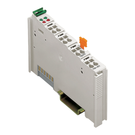
750-477 [2 AI AC/DC 0-10 V, Differential Inputs] • 7 View 2 I/O Modules 2.1 Analog Input Modules 2.1.1 750-477 [2 AI AC/DC 0-10 V, Differential Inputs] 2-Channel Analog Input Module (AC/DC 0-10 V, differential inputs) 2.1.1.1 View 13 14... -
Page 8: Display Elements
However, if such a case should occur, another supply module must be added. The analog input module 750-477 can be used with all couplers/controllers of the WAGO-I/O-SYSTEM 750 (except for the economy types 750-320, -323, - 324 and -327). -
Page 9: Schematic Diagram
750-477 [2 AI AC/DC 0-10 V, Differential Inputs] • 9 Schematic Diagram 2.1.1.4 Schematic Diagram 120 k +AI 1 +AI 2 Logic -AI 1 -AI 2 Error 10nF Function 10nF Shield Shield (screen) (screen) 750-477 Fig. 2.1.1-3: Schematic diagram g047701e... -
Page 10: Technical Data
(UL508) Conformity Marking More Information Detailed references to the approvals are listed in the document "Overview Approvals WAGO-I/O-SYSTEM 750", which you can find on the CD ROM ELECTRONICC Tools and Docs (Item-No.: 0888-0412) or in the internet under: www.wago.com ! Documentation ! WAGO-I/O-SYSTEM 750 ! -
Page 11: Process Image
Process Data" included in the description concerning the process image of the corresponding coupler/controller. For the standard module 750-477, the input voltage ranging from 0 V to 20 V is scaled on the numerical values ranging from 0x0000 to 0x4E20. - Page 12 WAGO Kontakttechnik GmbH & Co. KG Postfach 2880 • D-32385 Minden Hansastraße 27 • D-32423 Minden Phone: 05 71/8 87 – 0 Fax: 05 71/8 87 – 1 69 E-Mail: info@wago.com Internet: http://www.wago.com...
Need help?
Do you have a question about the 750-477 and is the answer not in the manual?
Questions and answers