Table of Contents
Advertisement
Quick Links
Manual
Pos: 2 /Dokumentation allgemein/Einband/Einband Frontseite - Handbuch; CI 2017; mit DocVariablen (Standard) @ 28\mod_1486477502910_0.docx @ 405388 @ @ 1
WAGO I/O SYSTEM 750 XTR
750-439/040-000
8DI NAMUR Ex i XTR
8-Channel Digital Input; NAMUR; Intrinsically Safe;
Extreme
Version 1.1.0
Pos: 3 /Alle Serien (Allgemeine Module)/Rechtliches, Allgemeines/Impressum für Standardhandbücher - allg. Angaben, Anschriften, Telefonnummern und E-Mail-Adressen @ 3\mod_1219151118203_21.docx @ 21060 @ @ 1
Advertisement
Table of Contents

Subscribe to Our Youtube Channel
Related Manuals for WAGO 750-439/040-000


Summary of Contents for WAGO 750-439/040-000
- Page 1 Manual Pos: 2 /Dokumentation allgemein/Einband/Einband Frontseite - Handbuch; CI 2017; mit DocVariablen (Standard) @ 28\mod_1486477502910_0.docx @ 405388 @ @ 1 WAGO I/O SYSTEM 750 XTR 750-439/040-000 8DI NAMUR Ex i XTR 8-Channel Digital Input; NAMUR; Intrinsically Safe; Extreme Version 1.1.0...
- Page 2 We wish to point out that the software and hardware terms as well as the trademarks of companies used and/or mentioned in the present manual are generally protected by trademark or patent. WAGO is a registered trademark of WAGO Verwaltungsgesellschaft mbH. === Ende der Liste für Textmarke Einband_vorne === Manual...
-
Page 3: Table Of Contents
WAGO I/O SYSTEM 750 XTR Table of Contents 750-439/040-000 8DI NAMUR Ex i XTR Pos: 5 /Dokumentation allgemein/Verzeichnisse/Inhaltsverzeichnis - Überschrift oG und Verzeichnis @ 3\mod_1219151230875_21.docx @ 21063 @ @ 1 Table of Contents Notes about this Documentation .............. 5 Validity of this Documentation ..............5 Copyright.................... - Page 4 Table of Contents WAGO I/O SYSTEM 750 XTR 750-439/040-000 8DI NAMUR Ex i XTR Connect Devices ..................40 Connecting a Conductor to the CAGE CLAMP ........40 ® Power Supply Concept ................41 6.2.1 Supplementary Power Supply Regulations ........44 Connection Example ................
-
Page 5: Notes About This Documentation
Pos: 9 /Alle Serien (Allgemeine Module)/Überschriften/Ebene 2/Gültigkeitsbereich - Überschrift 2 @ 12\mod_1338912448776_21.docx @ 96469 @ 2 @ 1 Validity of this Documentation Pos: 10 /Serie 750 (WAGO-I/O-SYSTEM)/Hinweise zur Dokumentation (alte Struktur)/Gültigkeitsbereich/Gültigkeitsbereich Dokumentation I/O-Modul 750-xxxx, ohne Variantenangabe @ 14\mod_1358944037947_21.docx @ 109346 @ @ 1 This documentation is only applicable to the I/O module 750-439/040-000 (8DI NAMUR Ex i XTR). -
Page 6: Symbols
Notes about this Documentation WAGO I/O SYSTEM 750 XTR 750-439/040-000 8DI NAMUR Ex i XTR Pos: 12.4 /Alle Serien (Allgemeine Module)/Überschriften/Ebene 2/Symbole - Überschrift 2 @ 13\mod_1351068042408_21.docx @ 105270 @ 2 @ 1 Symbols Pos: 12.5.1 /Alle Serien (Allgemeine Module)/Sicherheits- und sonstige Hinweise/Gefahr/Gefahr: _Warnung vor Personenschäden allgemein_ - Erläuterung @ 13\mod_1343309450020_21.docx @ 101029 @ @ 1... -
Page 7: Number Notation
WAGO I/O SYSTEM 750 XTR Notes about this Documentation 750-439/040-000 8DI NAMUR Ex i XTR Additional Information: Refers to additional information which is not an integral part of this documentation (e.g., the Internet). Pos: 12.6 /Dokumentation allgemein/Gliederungselemente/---Seitenwechsel--- @ 3\mod_1221108045078_0.docx @ 21810 @ @ 1 Pos: 12.7 /Alle Serien (Allgemeine Module)/Überschriften/Ebene 2/Darstellung der Zahlensysteme - Überschrift 2 @ 23\mod_1435647128078_21.docx @ 184811 @ 2 @ 1... -
Page 8: Important Notes
Use of the 750 Series in Compliance with Underlying Provisions Pos: 15.6 /Serie 750 (WAGO-I/O-SYSTEM)/Wichtige Erläuterungen (alte Struktur)/Bestimmungsgemäße Verwendung/Bestimmungsgemäße Verwendung 750-xxxx für Geräte - STD - mit EN 61000-6-3 @ 3\mod_1224064151234_21.docx @ 24070 @ @ 1 Fieldbus couplers, controllers and I/O modules found in the modular WAGO I/O SYSTEM 750 receive digital and analog signals from sensors and transmit them to actuators or higher-level control systems. -
Page 9: Technical Condition Of Specified Devices
These modules contain no parts that can be serviced or repaired by the user. The following actions will result in the exclusion of liability on the part of WAGO Kontakttechnik GmbH & Co. KG: •... -
Page 10: 2.1.4.1.2 Packaging
Important Notes WAGO I/O SYSTEM 750 XTR 750-439/040-000 8DI NAMUR Ex i XTR Environmentally friendly disposal benefits health and protects the environment from harmful substances in electrical and electronic equipment. • Observe national and local regulations for the disposal of electrical and electronic equipment. -
Page 11: Safety Advice (Precautions)
Always adhere to the EMC directives applicable to your application. Pos: 15.14 /Serie 750 (WAGO-I/O-SYSTEM)/Wichtige Erläuterungen (alte Struktur)/Sicherheits- und sonstige Hinweise/Warnung/Warnung: Speisung ausschließlich aus SELV-/PELV-Versorgung (24V-XTR-I/O-Module) @ 29\mod_1493107132163_21.docx @ 419618 @ @ 1 Power from SELV/PELV power supply only! - Page 12 Pos: 15.16.1 /Serie 750 (WAGO-I/O-SYSTEM)/Wichtige Erläuterungen (alte Struktur)/Sicherheits- und sonstige Hinweise/Achtung/Achtung: Einwandfreie Kontaktierung zur Tragschiene gewährleisten! @ 34\mod_1550481407638_21.docx @ 530599 @ @ 1 Ensure proper contact with the DIN-rail! Proper electrical contact between the DIN-rail and device is necessary to maintain the EMC characteristics and function of the device.
- Page 13 (personnel, work space and packaging) are properly grounded. Pos: 15.17 /Serie 750 (WAGO-I/O-SYSTEM)/Wichtige Erläuterungen (alte Struktur)/Sicherheits- und sonstige Hinweise/Achtung/Achtung: XTR - Isolationsprüfungen mit DC durchführen! @ 15\mod_1370843209441_21.docx @ 122210 @ @ 1 Use only direct current (DC) for insulation testing! Both the system voltage and field voltage side are capacitively coupled to the DIN-rail.
-
Page 14: Device Description
Pos: 18.1.2 /Serie 750 (WAGO-I/O-SYSTEM)/Wichtige Erläuterungen (alte Struktur)/Sicherheits- und sonstige Hinweise/Warnung/Warnung: Ex i Installation des WAGO-I/O-SYSTEM 750 nur in Zone 2 oder im nicht-ex-Bereich @ 5\mod_1245851655116_21.docx @ 35947 @ @ 1 Installation only in zone 2 or in non-hazardous environments! The installation of the WAGO I/O SYSTEM 750 fieldbus couplers/controllers and I/O modules is only to be done in zone 2 or in non-hazardous environments. - Page 15 An arrangement in groups within the group of potentials is not necessary. Pos: 18.1.13 /Serie 750 (WAGO-I/O-SYSTEM)/Gerätebeschreibung (alte Struktur)/Einleitung/Einsatzbereich/Einsatzbereich 750-xxxx/040-000 alle XTR-Koppler/Controller ohne Einschränkung+Mischbetriebhinweise @ 15\mod_1368425919479_21.docx @ 119444 @ @ 1 The I/O module can be operated with all fieldbus couplers/controllers of the WAGO I/O SYSTEM 750 XTR.
-
Page 16: View
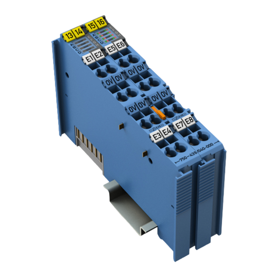
Pos: 18.4 /Serie 750 (WAGO-I/O-SYSTEM)/Gerätebeschreibung (alte Struktur)/Ansicht/DI/Ansicht 750-0439/0040-0000 @ 28\mod_1486126162443_21.docx @ 405232 @ @ 1 Figure 1: View Pos: 18.5 /Serie 750 (WAGO-I/O-SYSTEM)/Gerätebeschreibung (alte Struktur)/Ansicht/Ansicht CageClamp®_Legende mit LEDs, mit 1 Entriegelungslasche @ 15\mod_1370867188922_21.docx @ 122225 @ @ 1 Table 3: Legend for Figure “View”... -
Page 17: Connectors
Do not place the I/O modules on the gold spring contacts in order to avoid soiling or scratching! Pos: 18.9.3 /Serie 750 (WAGO-I/O-SYSTEM)/Wichtige Erläuterungen (alte Struktur)/Sicherheits- und sonstige Hinweise/Achtung/Achtung: ESD - Auf Potentialausgleich der Umgebung achten! @ 32\mod_1539077262331_21.docx @ 504433 @ @ 1 Pay attention to potential equalization from the environment! The devices are equipped with electronic components that may be destroyed by electrostatic discharge. -
Page 18: Power Jumper Contacts/Field Supply
Potential feed-in (U ) for field supply Pos: 18.12.5 /Serie 750 (WAGO-I/O-SYSTEM)/Wichtige Erläuterungen (alte Struktur)/Sicherheits- und sonstige Hinweise/Achtung/Achtung: Maximaler Strom Ex i Einspeisung 750-0606/040-000 XTR @ 28\mod_1486128985806_21.docx @ 405244 @ @ 1 Do not exceed maximum current via power contacts! The maximum current available from the “Power Supply 24 VDC Diagn for Ex i... -
Page 19: Cage Clamp
WAGO I/O SYSTEM 750 XTR Device Description 750-439/040-000 8DI NAMUR Ex i XTR Pos: 18.14 /Serie 750 (WAGO-I/O-SYSTEM)/Gerätebeschreibung (alte Struktur)/Anschlüsse/CAGE CLAMP-Anschlüsse - Überschrift 3 @ 6\mod_1256296337770_21.docx @ 43674 @ 3 @ 1 3.2.3 CAGE CLAMP Connectors ® Pos: 18.15 /Serie 750 (WAGO-I/O-SYSTEM)/Gerätebeschreibung (alte Struktur)/Anschlüsse/DI/Anschlüsse 750-0439/0x0-000 Tabelle @ 28\mod_1486122903338_21.docx @ 405213 @ @ 1 Table 5: Legend for Figure “CAGE CLAMP... -
Page 20: Display Elements
Pos: 18.17 /Alle Serien (Allgemeine Module)/Überschriften/Ebene 2/Anzeigeelemente - Überschrift 2 @ 4\mod_1240984390875_21.docx @ 31964 @ 2 @ 1 Display Elements Pos: 18.18.1 /Serie 750 (WAGO-I/O-SYSTEM)/Gerätebeschreibung (alte Struktur)/Anzeigeelemente/DI/Abbildung LEDs 750-0439/040-000 @ 34\mod_1556888110423_21.docx @ 542858 @ @ 1 Figure 4: Display Elements Pos: 18.18.2 /Serie 750 (WAGO-I/O-SYSTEM)/Gerätebeschreibung (alte Struktur)/Anzeigeelemente/DI/Anzeigeelemente 750-0439/040-000 @ 28\mod_1486126027669_21.docx @ 405229 @ @ 1... -
Page 21: Operating Elements
Pos: 18.20 /Alle Serien (Allgemeine Module)/Überschriften/Ebene 2/Bedienelemente - Überschrift 2 @ 4\mod_1239191655456_21.docx @ 30439 @ 2 @ 1 Operating Elements Pos: 18.21 /Serie 750 (WAGO-I/O-SYSTEM)/Gerätebeschreibung (alte Struktur)/Bedienelemente/Bedienelemente I/O-Modul 75x-xxxx nicht vorhanden @ 4\mod_1236322031125_21.docx @ 28063 @ @ 1 The I/O module 750-439/040-000 has no operating elements. -
Page 22: Technical Data
Pos: 18.25 /Alle Serien (Allgemeine Module)/Überschriften/Ebene 2/Technische Daten - Überschrift 2 @ 3\mod_1232967587687_21.docx @ 26924 @ 2 @ 1 Technical Data Pos: 18.26.1 /Serie 750 (WAGO-I/O-SYSTEM)/Gerätebeschreibung (alte Struktur)/Technische Daten/VS (Variablensteuerung)/Technische Daten Gerät (VS) - XTR @ 15\mod_1369311215011_21.docx @ 120260 @ 3 @ 1 3.6.1 Device Data Table 7: Technical Data –... -
Page 23: Inputs
Table 13: Technical Data – Data Contacts Data contacts Slide contact, self-cleaning, hard gold plated Pos: 18.26.5 /Serie 750 (WAGO-I/O-SYSTEM)/Gerätebeschreibung (alte Struktur)/Technische Daten/VS (Variablensteuerung)/Technische Daten Mechanische Bedingungen (VS) - XTR @ 15\mod_1369387569701_21.docx @ 120364 @ 3 @ 1 Manual Version 1.1.0... -
Page 24: Mechanical Conditions
Vibration resistance Max. 5g Follow the installation instructions Pos: 18.26.6 /Serie 750 (WAGO-I/O-SYSTEM)/Gerätebeschreibung (alte Struktur)/Technische Daten/VS (Variablensteuerung)/Technische Daten klimatische Umweltbedingungen (VS) - XTR @ 15\mod_1369387559187_21.docx @ 120360 @ 3 @ 1 3.6.7 Climatic Environmental Conditions Table 15: Technical Data ‒ Climatic Environmental Conditions Surrounding air temperature, operation −40 °C …... -
Page 25: Explosion Protection
WAGO I/O SYSTEM 750 XTR Device Description 750-439/040-000 8DI NAMUR Ex i XTR 3.6.8 Explosion Protection Table 16: Technical Data – Explosion Protection Power supply = 26.8 V via power jumper contacts = 1.2 W power consumption Interface circuit (system bus) -
Page 26: Approvals
Approvals Pos: 18.29 /Serie 750 (WAGO-I/O-SYSTEM)/Gerätebeschreibung (alte Struktur)/Zulassungen/komplett - NUR FÜR XTR ! (Allgemein, Ex, Schiff)/XTR (Paket 3)/Zulassungen XTR Bundle III (Ex i außer 606) @ 30\mod_1506082019831_21.docx @ 461793 @ @ 1 The following approvals have been granted for the I/O module 750-439/040-000:... - Page 27 Env. 1, 2, 3, 4 PRS (Polski Rejestr Statków) Pos: 18.30 /Serie 750 (WAGO-I/O-SYSTEM)/Gerätebeschreibung (alte Struktur)/Zulassungen/Information: Weitere Informationen zu Zulassungen 750-xxxx @ 3\mod_1227190967156_21.docx @ 25221 @ @ 1 More information about approvals. Detailed references to the approvals are listed in the document “Overview Approvals WAGO I/O SYSTEM 750”, which you can find via the internet under:...
-
Page 28: Standards And Guidelines
EN 60079-11 ed. 6 Equipment protection by intrinsic safety “i” Pos: null /Serie 750 (WAGO-I/O-SYSTEM)/Gerätebeschreibung (alte Struktur)/Normen und Richtlinien/Normen und Richtlinien XTR - Mechanik und Klima Komponenten-HB 2017 - Ex-i-Module @ 36\mod_1586553217517_21.docx @ 580429 @ @ 1 Manual Version 1.1.0... -
Page 29: Table 18: Climatic And Mechanical Environmental Conditions And
WAGO I/O SYSTEM 750 XTR Device Description 750-439/040-000 8DI NAMUR Ex i XTR Table 18: Climatic and Mechanical Environmental Conditions and Shipbuilding Standard Test Value Transport EN 60870-2-2 Ct2(2k4) (except precipitation/water/moisture) Mechanical Environmental Conditions EN 61850-3 Achieved EN 60870-2-2 EN 60721-3-1... -
Page 30: Table 19: Emc - Immunity To Interference
750-439/040-000 8DI NAMUR Ex i XTR Pos: 18.37 /Serie 750 (WAGO-I/O-SYSTEM)/Gerätebeschreibung (alte Struktur)/Normen und Richtlinien/EMV-Normen I/O-Modul 750-xxxx/0040-0000, nur Standardversion - Einleitung XTR @ 18\mod_1395909426189_21.docx @ 149708 @ @ 1 The I/O module 750-439/040-000 meets the following EMC standards as these standards relate to the I/O module: Pos: 18.38 /Serie 750 (WAGO-I/O-SYSTEM)/Gerätebeschreibung (alte Struktur)/Normen und Richtlinien/Normen Störfestigkeit XTR (Ex i Sonderfall -439) @ 31\mod_1515493438385_21.docx @ 473119 @ @ 1... - Page 31 EN 61000-4-16 or EN 60255-22-7 with respect to the power supply, shielded cables must be used at a cable length of 10 m or more. Pos: 18.39 /Serie 750 (WAGO-I/O-SYSTEM)/Gerätebeschreibung (alte Struktur)/Normen und Richtlinien/Normen Störaussendung XTR @ 18\mod_1394087664442_21.docx @ 147358 @ @ 1 Manual...
-
Page 32: Table 20: Emc - Emission Of Interference
Device Description WAGO I/O SYSTEM 750 XTR 750-439/040-000 8DI NAMUR Ex i XTR Table 20: EMC – Emission of Interference Standard Test Value Enclosure Emission of Interference • EN 61000-6-3 30 dB(µV/m), QP, 30 MHz … 230 MHz • EN 55032 Class B 37 dB(µV/m), QP, 230 MHz …... - Page 33 WAGO I/O SYSTEM 750 XTR Device Description 750-439/040-000 8DI NAMUR Ex i XTR Table 20: EMC – Emission of Interference Standard Test Value Conducted Emission of Interference – Line Connection DC Voltage • EN 61000-6-3 79 dB(µV) QP, 0.15 MHz … 0.5 MHz •...
-
Page 34: Process Image
Pos: 20 /Alle Serien (Allgemeine Module)/Überschriften/Ebene 1/Prozessabbild - Überschrift 1 @ 4\mod_1240983067828_21.docx @ 31942 @ 1 @ 1 Process Image Pos: 21 /Serie 750 (WAGO-I/O-SYSTEM)/Prozessabbild Lokalbus/Hinweis: Prozessabbildmapping abhängig von FBK/PFC, ohne Status-/Controlbyte XTR @ 18\mod_1396511070508_21.docx @ 150676 @ @ 1 Mapping of process data in the process image of fieldbus systems The representation of the process data of some I/O modules or their variations in the process image depends on the fieldbus coupler/controller used. -
Page 35: Table 23: Bit Connection
WAGO I/O SYSTEM 750 XTR Process Image 750-439/040-000 8DI NAMUR Ex i XTR Table 23: Bit Connection Byte 1 (0 … 7) Byte 0 (0 … 7) Description Broken wire/ Signal state DI short circuit DI Signal state “0” Signal state “1”... -
Page 36: Mounting
The blade contacts are sharp-edged. Handle the I/O module carefully to prevent injury. Do not touch the blade contacts. Pos: 25.3 /Serie 750 (WAGO-I/O-SYSTEM)/Wichtige Erläuterungen (alte Struktur)/Sicherheits- und sonstige Hinweise/Warnung/Warnung: Anforderungen an Luft- und Kriechstrecken (XTR Ex i) @ 36\mod_1579514444035_21.docx @ 572089 @ @ 1 Requirements for Clearances and Creepage Distances For all sections of a node that contain I/O modules for Ex-i use, stricter require- ments with regard to clearances and creepage distances apply. - Page 37 You must always use this bus end module at all fieldbus nodes with the WAGO I/O SYSTEM 750 XTR fieldbus couplers/controllers to guarantee proper data transfer. Pos: 25.6 /Serie 750 (WAGO-I/O-SYSTEM)/Montieren/Demontieren/I/O-Module 750xxxx/0040xxxx 4g-5g @ 15\mod_1367558844291_21.docx @ 118470 @ @ 1 For vibration loads > 4g, observe the following installation instructions: •...
-
Page 38: Inserting And Removing Devices
Switch off all power to the device prior to performing any installation, repair or maintenance work. Pos: 25.11 /Serie 750 (WAGO-I/O-SYSTEM)/Wichtige Erläuterungen (alte Struktur)/Sicherheits- und sonstige Hinweise/Achtung/Achtung: XTR nicht unter -20 °C verdrahten oder umstecken @ 15\mod_1367559895186_21.docx @ 118480 @ @ 1 Temperature range applies to normal operation! XTR I/O modules may be operated below −20 °C, but not wired and/or... -
Page 39: Removing The I/O Module
(if any) to the fieldbus coupler/controller or to the previous or possibly subsequent I/O module are established. Pos: 25.13 /Serie 750 (WAGO-I/O-SYSTEM)/Montieren/Demontieren/XTR-I/O-Modul entfernen @ 28\mod_1486551166032_21.docx @ 405491 @ 3 @ 1 5.2.2 Removing the I/O Module Remove the I/O module from the assembly by pulling the release tab. -
Page 40: Connect Devices
Pos: 27 /Alle Serien (Allgemeine Module)/Überschriften/Ebene 1/Geräte anschließen - Überschrift 1 @ 3\mod_1234172889468_21.docx @ 27460 @ 1 @ 1 Connect Devices Pos: 28 /Serie 750 (WAGO-I/O-SYSTEM)/Anschließen/Leiter an CAGE CLAMP anschließen (allgemein) - Überschrift 2 und Text @ 3\mod_1225448660171_21.docx @ 24928 @ 2 @ 1 Connecting a Conductor to the CAGE CLAMP ®... -
Page 41: Power Supply Concept
Ex i XTR I/O modules shall only be operated with a “Power Supply 24 VDC Diagn for Ex i XTR Modules” 750-606/040-000. Pos: 31.2 /Serie 750 (WAGO-I/O-SYSTEM)/Wichtige Erläuterungen (alte Struktur)/Sicherheits- und sonstige Hinweise/Warnung/Warnung: Anforderungen an Luft- und Kriechstrecken (XTR Ex i) @ 36\mod_1579514444035_21.docx @ 572089 @ @ 1 Requirements for Clearances and Creepage Distances For all sections of a node that contain I/O modules for Ex-i use, stricter require- ments with regard to clearances and creepage distances apply. -
Page 42: Figure 10: Ex I Xtr Power Supply Concept
The Ex i XTR I/O module (750-439/040-000) provides these potentials to subsequent I/O modules via the power contacts designed as spring contacts. Pos: 31.7 /Serie 750 (WAGO-I/O-SYSTEM)/Anschließen/Einspeisekonzepte/Ex-i-Einspeisung außerhalb Schiffsbereich XTR - Abbildung sprachneutral + Legende @ 28\mod_1487083585744_21.docx @ 407624 @ @ 1 Figure 10: Ex i XTR Power Supply Concept Table 26: Legend for Figure “Ex i XTR Power Supply Concept”... -
Page 43: Figure 11: Overvoltage Categories
WAGO I/O SYSTEM 750 XTR Connect Devices 750-439/040-000 8DI NAMUR Ex i XTR Figure 11: Overvoltage Categories Table 27: Legend for Figure “Overvoltage Categories” Pos. Explanation XTR fieldbus coupler/controller XTR filter module XTR supply module “Power Supply 24 VDC Diagn for Ex i XTR Modules”... -
Page 44: Supplementary Power Supply Regulations
(surge) Therefore, the following power supply concepts must be observed: Pos: 31.10.2 /Serie 750 (WAGO-I/O-SYSTEM)/Wichtige Erläuterungen (alte Struktur)/Sicherheits- und sonstige Hinweise/Warnung/Warnung: Ex-i-Schiffseinspeisung nur mit Filtermodul XTR @ 28\mod_1486133978849_21.docx @ 405282 @ @ 1 Use the appropriate filter module! When using Ex i XTR I/O modules in shipping, station control and telecontrol technology, the supply voltage of the “Power Supply 24 VDC Diagn for Ex i XTR... -
Page 45: Figure 12: Power Supply Concept, Example 1
WAGO I/O SYSTEM 750 XTR Connect Devices 750-439/040-000 8DI NAMUR Ex i XTR Figure 12: Power Supply Concept, Example 1 Table 29: Legend for Figure “Power Supply Concept, Example 1” Pos. Explanation XTR fieldbus coupler / controller XTR filter module 750-626/040-000 XTR supply “Power Supply 24 VDC Diagn for Ex i XTR Modules”... -
Page 46: Figure 13: Power Supply Concept, Example 2
WAGO I/O SYSTEM 750 XTR 750-439/040-000 8DI NAMUR Ex i XTR Pos: 31.10.4 /Serie 750 (WAGO-I/O-SYSTEM)/Anschließen/Einspeisekonzepte/ Ex-i-Einspeisekonzept mit 2 Filtermodulen XTR @ 28\mod_1486134344254_21.docx @ 405288 @ @ 1 Figure 13: Power Supply Concept, Example 2 Table 30: Legend for Figure “Power Supply Concept, Example 2“... -
Page 47: Connection Example
Pos: 33 /Alle Serien (Allgemeine Module)/Überschriften/Ebene 2/Anschlussbeispiel - Überschrift 2 @ 4\mod_1242621672468_21.docx @ 33293 @ 2 @ 1 Connection Example Pos: 34 /Serie 750 (WAGO-I/O-SYSTEM)/Anschließen/Anschlussbeispiele/Digitaleingänge/Anschlussbeispiel 750-439/040-000 XTR @ 28\mod_1486569749431_21.docx @ 405543 @ @ 1 Figure 14: Connection Example with 8 Sensors on Channel 1 to 8 Pos: 35 /Dokumentation allgemein/Gliederungselemente/---Seitenwechsel--- @ 3\mod_1221108045078_0.docx @ 21810 @ @ 1... -
Page 48: Use In Hazardous Environments
Pos: 36.1 /Alle Serien (Allgemeine Module)/Überschriften/Ebene 1/Einsatz in explosionsgefährdeten Bereichen - Überschrift 1 @ 3\mod_1224075191281_21.docx @ 24084 @ 1 @ 1 Use in Hazardous Environments Pos: 36.2 /Serie 750 (WAGO-I/O-SYSTEM)/Einsatz in Ex-Bereichen/Einsatzbereich Serie 750 @ 3\mod_1234272230203_21.docx @ 27500 @ @ 1 The WAGO I/O SYSTEM 750 (electrical equipment) is designed for use in Zone 2 hazardous areas and shall be used in accordance with the marking and installation regulations. -
Page 49: Marking Configuration Examples
7.1.1 Marking for Europe According to ATEX and IECEx Pos: 36.6 /Serie 750 (WAGO-I/O-SYSTEM)/Einsatz in Ex-Bereichen/Beispielbedruckung ATEX und IECEx_TUEV07_2017 @ 14\mod_1360569228625_21.docx @ 111294 @ @ 1 Figure 15: Marking Example According to ATEX and IECEx Figure 16: Text Detail – Marking Example According to ATEX and IECEx Manual Version 1.1.0... -
Page 50: Table 31: Description Of Marking Example According To Atex And Iecex
Use in Hazardous Environments WAGO I/O SYSTEM 750 XTR 750-439/040-000 8DI NAMUR Ex i XTR Table 31: Description of Marking Example According to ATEX and IECEx Marking Description TUEV 07 ATEX 554086 X Approving authority resp. certificate numbers IECEx TUN 09.0001 X... -
Page 51: Figure 17: Marking Example For Approved Ex I I/O Module According To
Use in Hazardous Environments 750-439/040-000 8DI NAMUR Ex i XTR Pos: 36.8 /Serie 750 (WAGO-I/O-SYSTEM)/Einsatz in Ex-Bereichen/Beispielbedruckung ATEX und IECEx_TUEV12_Ex i_2017 @ 14\mod_1360569320118_21.docx @ 111298 @ @ 1 Figure 17: Marking Example for Approved Ex i I/O Module According to ATEX and IECEx Figure 18: Text Detail –... -
Page 52: Table 32: Description Of Marking Example For Approved Ex I I/O Module According To Atex And Iecex
Use in Hazardous Environments WAGO I/O SYSTEM 750 XTR 750-439/040-000 8DI NAMUR Ex i XTR Table 32: Description of Marking Example for Approved Ex i I/O Module According to ATEX and IECEx Marking Description TUEV 12 ATEX 106032 X Approving authority resp. certificate numbers... -
Page 53: Marking For The United States Of America (Nec) And Canada (Cec)
Pos: 36.10 /Serie 750 (WAGO-I/O-SYSTEM)/Einsatz in Ex-Bereichen/Beispielbedruckung NEC und CEC_2017 @ 29\mod_1497866336326_21.docx @ 424745 @ @ 1 Figure 19: Marking Example According to NEC Pos: 36.11 /Serie 750 (WAGO-I/O-SYSTEM)/Einsatz in Ex-Bereichen/Beispielbedruckung und Textdetail NEC 500_2017 @ 14\mod_1360580302684_21.docx @ 111353 @ @ 1 Figure 20: Text Detail – Marking Example According to NEC 500... -
Page 54: Figure 21: Text Detail - Marking Example For Approved Ex I I/O Module
750-439/040-000 8DI NAMUR Ex i XTR Pos: 36.13 /Serie 750 (WAGO-I/O-SYSTEM)/Einsatz in Ex-Bereichen/Beispielbedruckung und Textdetail NEC 505_2017 @ 29\mod_1497865583500_21.docx @ 424739 @ @ 1 Figure 21: Text Detail – Marking Example for Approved Ex i I/O Module According to NEC 505... -
Page 55: Figure 23: Text Detail - Marking Example For Approved Ex I I/O Modules
750-439/040-000 8DI NAMUR Ex i XTR Pos: 36.16 /Serie 750 (WAGO-I/O-SYSTEM)/Einsatz in Ex-Bereichen/Beispielbedruckung und Textdetail CEC_2017 @ 29\mod_1497865583297_21.docx @ 424736 @ @ 1 Figure 23: Text Detail – Marking Example for Approved Ex i I/O Modules According to CEC 18... -
Page 56: Installation Regulations
7.2.1 Special Notes including Explosion Protection Pos: 36.21.2 /Serie 750 (WAGO-I/O-SYSTEM)/Einsatz in Ex-Bereichen/Besondere Hinweise einschließlich Explosionsschutz_2017 @ 29\mod_1491556994025_21.docx @ 415448 @ @ 1 The following warning notices are to be posted in the immediately proximity of the WAGO I/O SYSTEM 750 (hereinafter “product”): WARNING –... - Page 57 WAGO I/O SYSTEM 750 XTR Use in Hazardous Environments 750-439/040-000 8DI NAMUR Ex i XTR Explosive atmosphere occurring simultaneously with assembly, installation or repair work must be ruled out. Among other things, these include the following activities • Insertion and removal of components •...
-
Page 58: Special Notes Regarding Ansi/Isa Ex
Pos: 36.21.4 /Alle Serien (Allgemeine Module)/Überschriften/Ebene 3/Besondere Hinweise hinsichtlich ANSI/ISA Ex - Überschrift 3 @ 29\mod_1491558494822_21.docx @ 415468 @ 3 @ 1 7.2.2 Special Notes Regarding ANSI/ISA Ex Pos: 36.21.5 /Serie 750 (WAGO-I/O-SYSTEM)/Einsatz in Ex-Bereichen/ANSI/ISA gemäß UL File E198726_2017 @ 29\mod_1491557259544_21.docx @ 415451 @ @ 1 For ANSI/ISA Ex acc. to UL File E198726, the following additional requirements apply: •... -
Page 59: List Of Figures
WAGO I/O SYSTEM 750 XTR List of Figures 750-439/040-000 8DI NAMUR Ex i XTR Pos: 38 /Dokumentation allgemein/Verzeichnisse/Abbildungsverzeichnis - Überschrift oG und Verzeichnis @ 3\mod_1219222916765_21.docx @ 21080 @ @ 1 List of Figures Figure 1: View ...................... 16 Figure 2: Data Contacts ..................17 Figure 3: Power Jumper Contacts ............... -
Page 60: List Of Tables
List of Tables WAGO I/O SYSTEM 750 XTR 750-439/040-000 8DI NAMUR Ex i XTR Pos: 40 /Dokumentation allgemein/Verzeichnisse/Tabellenverzeichnis - Überschrift oG und Verzeichnis @ 3\mod_1219222958703_21.docx @ 21084 @ @ 1 List of Tables Table 1: Number Notation ..................7 Table 2: Font Conventions ..................7 Table 3: Legend for Figure “View”... - Page 61 WAGO I/O SYSTEM 750 XTR List of Tables 750-439/040-000 8DI NAMUR Ex i XTR === Ende der Liste für Textmarke Verzeichnis_hinten === Manual Version 1.1.0...
- Page 62 Pos: 43 /Dokumentation allgemein/Einband/Einband Rückseite - alle Dokumente; CI 2017 @ 28\mod_1486477503580_21.docx @ 405394 @ @ 1 WAGO Kontakttechnik GmbH & Co. KG Postfach 2880 • D - 32385 Minden Hansastraße 27 • D - 32423 Minden Phone: +49 571 887 – 0 Fax: +49 571 887 –...
Need help?
Do you have a question about the 750-439/040-000 and is the answer not in the manual?
Questions and answers