Sign In
Upload
Manuals
Brands
WAGO Manuals
Control Unit
8DI NAMUR Ex i XTR
WAGO 8DI NAMUR Ex i XTR Manuals
Manuals and User Guides for WAGO 8DI NAMUR Ex i XTR. We have
2
WAGO 8DI NAMUR Ex i XTR manuals available for free PDF download: Manual
WAGO 8DI NAMUR Ex i XTR Manual (62 pages)
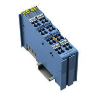
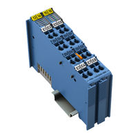
8-Channel Digital Input Module NAMUR, Ex i, Proximity Sensor acc. to EN 60947-5-6 For WAGO-I/O-SYSTEM 750
Brand:
WAGO
| Category:
Control Unit
| Size: 3.67 MB
Table of Contents
Table of Contents
3
1 Notes about this Documentation
5
Validity of this Documentation
5
Revision History
5
Table 1: Revision History
5
Copyright
6
Symbols
7
Number Notation
9
Font Conventions
9
Table 2: Number Notation
9
Table 3: Font Conventions
9
2 Important Notes
10
Legal Bases
10
Subject to Changes
10
Personnel Qualifications
10
Use of the 750 Series in Compliance with Underlying Provisions
10
Technical Condition of Specified Devices
11
Disposal
11
2.1.4.1.1 Electrical and Electronic Equipment
11
2.1.4.1.2 Packaging
12
Safety Advice (Precautions)
13
3 Device Description
15
View
16
Figure 1: View
16
Table 4: Legend for Figure "View
16
Connectors
17
Data Contacts/Local Bus
17
Figure 2: Data Contacts
17
Power Jumper Contacts/Field Supply
18
Figure 3: Power Jumper Contacts
18
Table 5: Legend for Figure "Power Jumper Contacts
18
Cage Clamp
19
Figure 4: CAGE CLAMP ® Connectors
19
Table 6: Legend for Figure "CAGE CLAMP ® Connectors
19
Display Elements
20
Figure 5: Display Elements
20
Table 7: Legend for Figure "Display Elements
20
Operating Elements
21
Schematic Diagram
21
Figure 6: Schematic Diagram
21
Technical Data
22
Dimensions and Weight
22
Power Supply
22
Communication
22
Table 8: Technical Data - Dimensions and Weight
22
Table 9: Technical Data - Power Supply
22
Table 10: Technical Data - Communication
22
Inputs
23
Figure 7: Current-Voltage Characteristic of the Control Input Per
23
Table 11: Technical Data - Inputs
23
Explosion Protection
24
Table 12: Legend for Figure "Current-Voltage Characteristic of the Control
24
Table 13: Technical Data - Explosion Protection
24
Connection Type
25
Climatic Environmental Conditions
25
Table 14: Technical Data - Field Wiring
25
Table 15: Technical Data - Power Jumper Contacts
25
Table 16: Technical Data - Data Contacts
25
Table 17: Technical Data - Climatic Environmental Conditions
25
Approvals
26
Standards and Guidelines
28
4 Process Image
30
Table 18: Input Byte D0 (Signal Status)
30
Table 19: Input Byte D1 (Error Status)
30
Table 20: Bit Combination with a Connected Sensor Functioning as a Make
31
Table 21: Combinations with a Connected Sensor Functioning as a Break
31
Table 22: Output Byte D0 (Enable Sensor Type NC)
32
Table 23: Output Byte D1 (Diagnostic Status)
33
5 Mounting
34
Mounting Sequence
35
Inserting and Removing Devices
36
Inserting the I/O Module
36
Figure 8: Inserting I/O Module (Example)
36
Figure 9: Snap the I/O Module into Place (Example)
36
Removing the I/O Module
37
Figure 10: Removing the I/O Module (Example)
37
6 Connect Devices
38
Connecting a Conductor to the CAGE CLAMP
38
Figure 11: Connecting a Conductor to a CAGE CLAMP
38
Power Supply Concept
39
Figure 12: Supply Principle Ex I
40
Table 24: Legend for Figure "Ex I Power Supply Concept
40
Power Supply Concept for Marine Applications in Ex I
41
Figure 13: Overvoltage Categories
41
Table 25: Legend for Figure "Overvoltage Categories
41
Figure 14: Power Supply Concept for Marine Applications in Ex I - Class a (Shown with 750-624/XXX-XXX for Field 2)
42
Table 26: Legend for Figure "Power Supply Concept for Marine Applications in Ex I - Class a (Shown with 750-624/XXX-XXX for Field 2)
42
Table 27: Explanation of the Legend for Figure "Power Supply Concept for
42
Figure 15: Power Supply Concept for Marine Applications in Ex I - Class B (Shown with 750-626/XXX-XXX for Field 2)
43
Table 28: Legend for Figure "Power Supply Concept for Marine Applications in Ex I - Class B (Shown with 750-626/XXX-XXX for Field 2)
43
Table 29: Explanation of the Legend for Figure "Power Supply Concept for
43
Connection Example
44
Figure 16: Connection Example with 8 Sensors on Channel 1 to 8
44
7 Commissioning
45
Wago-I/O-Check
45
Figure 17: Rename I/O Module
45
E!Cockpit
46
Figure 18: Setting Options in WAGO-I/O-CHECK
46
Table 30: Setting Options Per Channel
46
8 Diagnostics
47
Diagnostics Via LED Indicators
47
Table 31: Signal Evaluation for each Channel, LED A-H
47
9 Use in Hazardous Environments
48
Marking Configuration Examples
49
Marking for Europe According to ATEX and Iecex
49
Figure 19: Marking Example Per ATEX and Iecex
49
Figure 20: Text Detail - Marking Example Per ATEX and Iecex
49
Table 32: Description of the Marking Example Per ATEX and Iecex
50
Figure 21: Marking Example of an Approved I/O Module Ex I Per ATEX and
51
Figure 22: Text Detail - Marking Example of an Approved I/O Module Ex I Per ATEX and Iecex
51
Table 33: Description of the Marking Example of an Approved I/O Module Ex I Per ATEX and Iecex
52
Marking for the United States of America (NEC) and Canada (CEC)
53
Figure 23: Marking Example According to NEC
53
Figure 24: Text Detail - Marking Example According to NEC 500
53
Table 34: Description of Marking Example According to NEC 500
53
Figure 25: Text Detail - Marking Example for Approved Ex I I/O Module
54
Figure 26: Text Detail - Marking Example for Approved Ex I I/O Module
54
Table 35: Description of Marking Example for Approved Ex I I/O Module
54
Figure 27: Text Detail - Marking Example for Approved Ex I I/O Modules
55
Installation Regulations
56
Special Notes Including Explosion Protection
56
Special Notes Regarding UL Hazardous Location
58
List of Figures
59
List of Tables
60
Advertisement
WAGO 8DI NAMUR Ex i XTR Manual (62 pages)
8-Channel Digital Input; NAMUR; Intrinsically Safe; Extreme For WAGO I/O SYSTEM 750 XTR
Brand:
WAGO
| Category:
Control Unit
| Size: 3.2 MB
Table of Contents
Table of Contents
3
Notes about this Documentation
5
Validity of this Documentation
5
Copyright
5
Symbols
6
Number Notation
7
Font Conventions
7
Table 1: Number Notation
7
Table 2: Font Conventions
7
Important Notes
8
Legal Bases
8
Subject to Changes
8
Personnel Qualifications
8
Use of the 750 Series in Compliance with Underlying Provisions
8
Technical Condition of Specified Devices
9
Disposal
9
2.1.4.1.1 Electrical and Electronic Equipment
9
2.1.4.1.2 Packaging
10
Safety Advice (Precautions)
11
Device Description
14
View
16
Figure 1: View
16
Table 3: Legend for Figure "View
16
Connectors
17
Data Contacts/Local Bus
17
Figure 2: Data Contacts
17
Power Jumper Contacts/Field Supply
18
Figure 3: Power Jumper Contacts
18
Table 4: Legend for Figure "Power Jumper Contacts
18
Cage Clamp
19
Table 5: Legend for Figure "CAGE CLAMP ® Connectors
19
Display Elements
20
Figure 4: Display Elements
20
Table 6: Legend for Figure "Display Elements
20
Operating Elements
21
Schematic Diagram
21
Figure 5: Schematic Diagram
21
Technical Data
22
Device Data
22
Power Supply
22
Table 7: Technical Data - Device
22
Table 8: Technical Data - Power Supply
22
Inputs
23
Communication
23
Connection Type
23
Table 9: Technical Data - Inputs
23
Table 10: Technical Data - Communication
23
Table 11: Technical Data - Field Wiring
23
Table 12: Technical Data - Power Jumper Contacts
23
Table 13: Technical Data - Data Contacts
23
Mechanical Conditions
24
Climatic Environmental Conditions
24
Table 14: Technical Data - Mechanical Conditions
24
Table 15: Technical Data - Climatic Environmental Conditions
24
Explosion Protection
25
Table 16: Technical Data - Explosion Protection
25
Approvals
26
Standards and Guidelines
28
Table 17: Standards and Rated Conditions for Explosion Protection
28
Table 18: Climatic and Mechanical Environmental Conditions and
29
Table 19: EMC - Immunity to Interference
30
Table 20: EMC - Emission of Interference
32
Process Image
34
Table 21: Input Byte D0 (Signal State)
34
Table 22: Input Byte D1 (Error State)
34
Table 23: Bit Connection
35
Table 24: Output Byte D0 (Reserved)
35
Table 25: Output Byte D1 (Diagnostic State)
35
Mounting
36
Mounting Sequence
36
Inserting and Removing Devices
38
Inserting the I/O Module
38
Figure 6: Insert I/O Module (Example)
38
Removing the I/O Module
39
Figure 7: Snap the I/O Module into Place (Example)
39
Figure 8: Removing the I/O Module (Example)
39
Connect Devices
40
Connecting a Conductor to the CAGE CLAMP
40
Figure 9: Connecting a Conductor to a CAGE CLAMP
40
Power Supply Concept
41
Figure 10: Ex I XTR Power Supply Concept
42
Table 26: Legend for Figure "Ex I XTR Power Supply Concept
42
Figure 11: Overvoltage Categories
43
Table 27: Legend for Figure "Overvoltage Categories
43
Supplementary Power Supply Regulations
44
Table 28: Filter Modules for 24V Power Supply
44
Figure 12: Power Supply Concept, Example 1
45
Table 29: Legend for Figure "Power Supply Concept, Example 1
45
Figure 13: Power Supply Concept, Example 2
46
Table 30: Legend for Figure "Power Supply Concept, Example 2
46
Connection Example
47
Figure 14: Connection Example with 8 Sensors on Channel 1 to 8
47
Use in Hazardous Environments
48
Marking Configuration Examples
49
Marking for Europe According to ATEX and Iecex
49
Figure 15: Marking Example According to ATEX and Iecex
49
Figure 16: Text Detail - Marking Example According to ATEX and Iecex
49
Table 31: Description of Marking Example According to ATEX and Iecex
50
Figure 17: Marking Example for Approved Ex I I/O Module According to
51
Figure 18: Text Detail - Marking Example for Approved Ex I I/O Module According to ATEX and Iecex
51
Table 32: Description of Marking Example for Approved Ex I I/O Module According to ATEX and Iecex
52
Table 34: Description of Marking Example for Approved Ex I I/O Module
52
Marking for the United States of America (NEC) and Canada (CEC)
53
Figure 19: Marking Example According to NEC
53
Figure 20: Text Detail - Marking Example According to NEC 500
53
Table 33: Description of Marking Example According to NEC 500
53
Figure 21: Text Detail - Marking Example for Approved Ex I I/O Module
54
Figure 22: Text Detail - Marking Example for Approved Ex I I/O Module
54
Table 35: Description of Marking Example for Approved Ex I I/O Modules
54
Figure 23: Text Detail - Marking Example for Approved Ex I I/O Modules
55
Table 36: Description of Marking Example for Approved Ex I I/O Modules
55
Installation Regulations
56
Special Notes Including Explosion Protection
56
Special Notes Regarding ANSI/ISA Ex
58
List of Figures
59
List of Tables
60
Advertisement
Related Products
WAGO 852-103
WAGO ETHERNET Accessories 852 852-0111
WAGO 852-1322
WAGO 852-1328
WAGO 852-1112
WAGO 879-3020
WAGO 879-3000
WAGO 879-3000 4PU
WAGO 879-3040 2PU CT
WAGO 852-111/000-001
WAGO Categories
I/O Systems
Control Unit
Power Supply
Switch
Controller
More WAGO Manuals
Login
Sign In
OR
Sign in with Facebook
Sign in with Google
Upload manual
Upload from disk
Upload from URL