GILES GGF Series Operation & Service Manual
Hide thumbs
Also See for GGF Series:
- Operation & service manual (99 pages) ,
- Operation & service manual (89 pages)
Table of Contents
Advertisement
Operations & Service Manual
ISO 9001 Registered • Committed to Quality
2750 Gunter Park Drive West • Montgomery, AL 36109 USA
Toll Free: 800.554.4537
(USA & Canada Only)
Fax: 334.239.4117 • Website: www.gfse.com • Email: services@gfse.com
Printed in USA, Form No. 65474 (Rel. Jan.2009; Rev. Mar.2020; Rev. G)
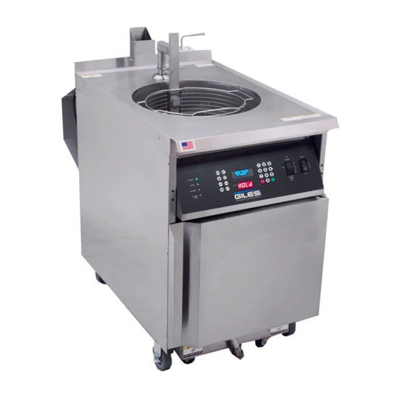
GGF Series Fryer
Model
GGF-400
GGF-720
Other: 334.272.1457
Advertisement
Table of Contents

Related Manuals for GILES GGF Series


Summary of Contents for GILES GGF Series
- Page 1 Operations & Service Manual GGF Series Fryer Model GGF-400 GGF-720 ISO 9001 Registered • Committed to Quality 2750 Gunter Park Drive West • Montgomery, AL 36109 USA Toll Free: 800.554.4537 Other: 334.272.1457 (USA & Canada Only) Fax: 334.239.4117 • Website: www.gfse.com • Email: services@gfse.com...
- Page 2 IN A PROMINENT LOCATION, post instruction for actions to be taken in the event users smells gas. This information can be obtained by contacting the local gas utility company. FOR YOUR SAFETY DO NOT store or use flammable liquids or materials, or those which may produce flammable vapors, in the vicinity of this or any other appliance.
- Page 3 • During the Limited Warranty period, Giles will replace or recondition, at its factory, any part or parts of this unit which Giles inspectors judge defective, provided the unit has been properly installed, subjected to normal usage, and operated and maintained in accordance with specified procedures.
-
Page 4: Table Of Contents
Table Of Contents Model: GGF-400, GGF-720 Safety ..............v Safety Overview . - Page 5 Table Of Contents Model: GGF-400, GGF-720 Fryer Operation ..........35 5.1.
-
Page 6: Safety
The instructions contained in this manual have been prepared to aid in learning the proper procedures for installing, operating and servicing Giles Model GGF Series Gas Fryer. Throughout the manual, safety precautions are identified by a hazard alert symbol and key words such as DANGER, WARNING or CAUTION. -
Page 7: Specific Safety Precautions
Model: GGF-400, GGF-720 Specific Safety Precautions: For your safety, please observe the following precautions when operating or servicing the GGF Series Gas Fryer. Adhering to the following important safety precautions will help Users to avoid personal injury and/or damage to the equipment. - Page 8 Safety Model: GGF-400, GGF-720 • The appliance must remain in an upright position. • Exercise care when removing the unit from shipping pallet. • DO NOT operate the appliance, unless its components and their intended functions are fully understood (see Section 3).
- Page 9 Safety Model: GGF-400, GGF-720 NOTE: • If upon receipt, the palletized unit showed any signs of damage, you should immediately inspect the appliance and associated accessories, and notify the freight carrier of any and all damages. • Comply with all appropriate state and/or local heath regulations regarding cleaning and sanitization of foodservice equipment.
-
Page 10: Introduction
Model: GGF-400, GGF-720 Introduction THANK YOU for purchasing the Giles Model GGF Series Gas Fryer, manufactured by GILES Food Service Equipment; Montgomery, Alabama (USA), hereafter referred to as "Giles". Every unit is thoroughly inspected and tested prior to shipment in efforts to ensure that it will operate flawlessly when installed. With proper care and maintenance the appliance will provide years of trouble-free service. -
Page 11: Specifications
Introduction Model: GGF-400, GGF-720 1.4. Specifications 1.4.1. Overall Dimensions: GGF-400 & GGF-720 42 11/32 21 7/8 556mm 24 3/8 619mm... -
Page 12: Agency Certifications
Introduction Model: GGF-400, GGF-720 1.4.2. Agency Certifications 1.4.3 Basket Sizes Basket Size Volume Model Diameter: in [mm] Height: in [mm] Cubic inch [Cu m] GGF-400 12-3/8 [314.2] 10-1/4 [260.4] 1,231.8 [.020] GGF-720 14-3/4 [374.7] 12-3/4 [323.9] 2,178.6 [.036] 1.4.4 Cooking Capacity Cooking Oil Capacity** Product Capacity (*Chicken) Model... - Page 13 Introduction Model: GGF-400, GGF-720...
-
Page 14: Installation
GGF-400, GGF-720 Installation This section summarizes procedures necessary for proper installation of the GGF Series Gas Fryer. To prevent personal injury or damage to the equipment, please ensure the following steps are taken and the following check sheet is initialed and dated. - Page 15 Typically it is the purchaser’s responsibility to file and negotiate freight damage claims. Giles is not liable for damages to the unit caused by use of improper material handling equipment or poor work practices, or for personal injuries or property damage which may be incurred during installation of this equipment.
-
Page 16: Clearances, Gas Supply And Electrical Locations
Installation GGF-400, GGF-720 2.3. Clearances, Gas Supply and Electrical Locations COMBUSTIBLES 18”[457.2] NON-COMBUSTIBLES 4”[101.6] 4”[101.6] NON-COMBUSTIBLES 18”[457.2] COMBUSTIBLES 42 25/32 24 3/8 1086.51 619mm REGULATOR W/1/2” NPT GAS LINE CONNECTION 6’ POWER CORD INCLUDED... -
Page 17: Ventilation
Installation GGF-400, GGF-720 2.4. Ventilation NOTE: Guidelines for ventilation system requirements may differ by locale. Always consult with local authorities to ensure compliance for this appliance. • The combustion gases produced by this appliance must be vented to the outside in accordance with the prevailing National Fuel Gas Code, ANSI Z223.1 and terminate with a UL listed outside vent terminal. -
Page 18: Electrical Connections
Installation GGF-400, GGF-720 2.6. Electrical Connections 1. Connect Fryer power cord to an appropriate receptacle ... the circuit must have properly sized circuit breaker and wiring of sufficient gauge to power the appliance, See Table 2.5.1. 2. Fryer is equipped with power cord with molded plug. IMPORTANT! When installed, appliance must be electrically grounded in accordance with local code, or in the absence of local code, with the National Electrical Code, ANSI/NFPA 70, or Canadian Electrical Code, CSA C22.2, as applicable. -
Page 19: Typical Gas Supply Line Connection
Installation GGF-400, GGF-720 2.7.1 Typical Gas Supply Line Connection IMPORTANT! • Installation must comply with local code, or in the absence of local code, with the National Fuel Gas Code, ANSI Z223.1/NFPA 54 [in Canada, Natural Gas and Propane Installation Code, CSA B149.1] including: •... - Page 20 Installation GGF-400, GGF-720 2.7.1 Typical Gas Supply Line Connection - continued IMPORTANT! The factory-installed regulator on the fryer controls gas pressure supplied to the gas valve as shown in Table 5- 2.2. This regulator is rated for max. input pressure of 13.85” W.C. [ 3.45 kPa]. If supply line pressure exceeds this maximum, a secondary regulator must be installed in the supply line, upstream of the installed regulator, to maintain pressure at or below the maximum rating.
-
Page 21: Gas Orifices: Informations & Replacement Procedure
To confirm that proper orifices are installed or to exchange, follow the steps below. Orifices are available from Giles (call factory at 800.554.4537) and it is possible that they may also be sourced locally; consult charts below. -
Page 22: Gas Pressure Setting And Adjustment
Installation GGF-400, GGF-720 2.9. Gas Pressure Setting & Adjustment The following procedure is for setting the Fryer gas valve to the proper incoming gas pressure. This ensures that the BTU output of the burners is at the correct level. Requires a digital Manometer capable of reading Inches W.C. (water column). -
Page 23: Blower Vacuum Switch Setting And Adjustment
Installation GGF-400, GGF-720 2.10. Blower Vacuum Switch Setting & Adjustment The Blower Vacuum Switch ensures that the unit has proper draft air-flow before allowing the gas valve to open for ignition. The switch has been factory set, but differences in conditions at the installation site may affect the setting. Use the following steps to confirm that the Blower Vacuum Switch is adjusted properly for local conditions. -
Page 24: Restraint Device
Installation GGF-400, GGF-720 2.11. Restraint Device This unit requires use of a Restraint Device (not provided) to prevent Fryer from being unintentionally moved and prevent strain on electrical and gas connections. The Restraint Cable length must be shorter than both electrical cord (or conduit) and the flexible gas line. -
Page 25: Overview
Overview Model: GGF-400, GGF-720 Overview The following section provides a brief overview of components, features and accessories associated with the Giles GGF Series Fryer. Please review this section completely before attempting to use the appliance. Basket & Elevator Assembly Section 3.4. -
Page 26: Control Panel
Model: GGF-400, GGF-720 Overview 3.1. Control Panel... - Page 27 Overview Model: GGF-400, GGF-720 3.1. Control Panel Item Description Function 2-position rocker switch, turns appliance power ON & OFF. Pressing top of Power Switch switch powers ON, pressing bottom powers OFF. 3-position rocker switch, selects appliance mode of operation ... [COOK]- [OFF]-[FILTER PUMP].
-
Page 28: Lower Cabinet
Model: GGF-400, GGF-720 Overview 3.2. Lower Cabinet... - Page 29 Overview Model: GGF-400, GGF-720 3.2. Lower Cabinet Item Description Function Directs the discharge from the Filter Pump either to the Fry Pot, or to the Diverter Valve Handle Waste Oil Discharge Hose. Waste Oil Discharge Hose Connects the Waste Oil Discharge Hose to the Fryer Filter Pump system for Quick-disconnect removal of waste oil.
-
Page 30: Filter Pan Assembly
Model: GGF-400, GGF-720 Overview 3.3. Filter Pan Assembly * Non-standard; Sold separately; Not Included... - Page 31 Overview Model: GGF-400, GGF-720 3.3. Filter Pan Assembly Item Description Function *OPTIONAL, SOLD SEPARATELY, NOT INCLUDED Crumb Screen Designed to capture larger breading crumbs, cooking offal and residue as oil drains into the Filter Pan. Secures filter media tightly against Filter Pan bottom to provide a good Hold-Down Frame suction seal.
-
Page 32: Basket And Elevator Assembly
Model: GGF-400, GGF-720 Overview 3.4. Basket and Elevator Assembly... - Page 33 Overview Model: GGF-400, GGF-720 3.4. Basket and Elevator Assembly Item Description Function Covers Fry Pot during the cooking cycle. When in place prevents hot Basket Cover cooking oil from splashing or splattering out of Pot. Basket Carrier Holds Fry Basket as it is lower and raised by the Auto-Basket Lift. Basket Contains product while cooking.
- Page 34 Model: GGF-400, GGF-720 Overview 3.5. Accessories Included Part Description/Part Number Function Use to clean Fry Pot Drain and Kettle Drain Brush between back the Heat Exchanger P/N 71025 Ring and pot wall. Stirring Utensil Use to stir cooking oil and product in P/N 77775 the pot as it is cooked.
-
Page 35: Accessories Included
Overview Model: GGF-400, GGF-720 3.5. Accessories Included Part Description/Part Number Function Use for removing liquid shortening from unit. Discharge Hose Assembly P/N 33667 NOTE: DO NOT USE TO WASH DOWN THE COOK VAT! -
Page 36: Accessories Not Included
Model: GGF-400, GGF-720 Overview 3.6. Accessories Not Included Part Description/Part Number Function Filter Paper Filter media to be use in Filter Pan fo P/N 60810 filtering cooking oil. Filter aid for use when filtering Filter Powder cooking; helps recondition oil by P/N 72004 removing soluble impurities. - Page 37 Part Description/Part Number Function A portable oil disposal container with a capacity of 80-lbs of liquid shortening. Giles Oil Caddy P/N 79187 Intended to handle only warm, filtered oil, containing no crumbs or debris. Filter Pan insert helps prevent larger...
- Page 38 Model: GGF-400, GGF-720 Overview Notes:...
- Page 39 Preparation for Operating Fryer Giles takes pride in quality of workmanship. Every effort has been made to ensure that new equipment is in perfect operating condition when received. Every unit must pass rigorous quality control testing prior to shipment and to further ensure that it meets your expectations, it is recommended that this operational checkout and preparation be performed prior to using the fryer for the first time.
-
Page 40: Power Test
Model: GGF-400, GGF-720 Fryer Preparation 4.2. Power Test The following verifies that the appliance is receiving power. 1. Be sure the circuit breaker in the electrical panel powering the fryer is ON. ① ② 2. Place the Power Switch in the [ON] position. The green POWER light should come ON and the controller ③... -
Page 41: Filter Pump Test
Fryer Preparation Model: GGF-400, GGF-720 4.4. Filter Pump Test The following test will verify that the Filter Pump is operating correctly. ① 1. Place the Power Switch in the [ON] position. 3. Open cabinet door. 4. With the filter pan disconnected, place the palm of the hand tightly over the Filter Pan Hose ②... - Page 42 Fryer Preparation Model: GGF-400, GGF-720...
-
Page 43: Fryer Operation
Model: GGF-400, GGF-720 Fryer Operation This section describes operating procedures for the Giles Model GGF-400 & GGF-720 Gas Fryer. • Turn off the fryer power switch and the main supply power at the main circuit breaker panel, or remove plug for receptacle before cleaning or servicing. -
Page 44: Computer Cooking Controller
Fryer Operation Model: GGF-400, GGF-720 Computer Cooking Controller The following sections explain the functions, features, programming, and operational procedures for the Computer Cooking Controller. 5.1.1 Keys and Functions Numeric Keypad: Used for entering Fryer settings and to edit preset Menu Item cooking parameters. - Page 45 Fryer Operation Model: GGF-400, GGF-720 5.1.1 Keys and Functions - continued MENU Key: Action key which is pressed in combination with other keys to access programmed menu presets. Fifty (50) different Menu Item cooking presets can be programmed. EDIT Key: This is an action key which is pressed in combination with other keys to enter edit mode for changing or creating Menu preset settings.
-
Page 46: General Operation - Fryer Controller
Fryer Operation Model: GGF-400, GGF-720 5.1.2 General Operation - Fryer Controller The following is general operational information only. Detailed procedures and instructions are covered in subsequent sections. During operation, certain instructions and prompts will be shown on the Upper OLED Display to step Users through processes. -
Page 47: Manually Setting A Cook Time & Cooking Temperature
Fryer Operation Model: GGF-400, GGF-720 5.1.3 Manually Setting a Cook Time & Cooking Temperature The following explains the process for manually entering a cooking time and temperature. Before setting a Temperature, be sure the Selector Switch is in the [OFF] position and that Pot is filled with cooking oil.. - Page 48 Fryer Operation Model: GGF-400, GGF-720 5.1.4 Working with Menu Item Presets Fifty (50) Menu Item Preset cook settings are stored in the Controller, each includes: ● Menu # - Sequential ID number ● Menu Name - Name of the food item assigned to the preset. ●...
-
Page 49: Editing A Menu Item Preset
Fryer Operation Model: GGF-400, GGF-720 5.1.4.1 Editing a Menu Item Preset Two different methods can be used to edit the item NAME Editing [NAME] - Method 1: Enter NAME letter by letter. Select the NAME as shown on left. A flashing cursor is Use Up [2] - Down [8] to scroll positioned at 1st letter. - Page 50 Fryer Operation Model: GGF-400, GGF-720 5.1.4.1 Editing a Menu Item Preset - continued Edit COOKING TIME: Scroll to and select TIME for edit as shown on previous page. Current time setting will be displayed. Use numeric keypad to enter new TIME (mm:ss) NOTE: All digits must be entered, e.g.
- Page 51 Fryer Operation Model: GGF-400, GGF-720 5.1.4.1 Editing a Menu Item Preset - continued Edit STIR OVERRIDE Setting: Regardless of the global STIR ALARM setting in User Settings (Section 5.1.7), a menu item may, or may not, need to be stirred during the cook cycle. STIR OVERRIDE setting allows user to override global setting only for a specific Menu Item, if desired.
-
Page 52: 5.1.4.2 Selecting A Menu Preset For Cooking
Fryer Operation Model: GGF-400, GGF-720 5.1.4.2 Selecting a Menu Preset for Cooking Before selecting a menu preset, be sure that Selector Switch on control panel is in the [OFF] position and that pot is filled with cooking oil. Direct Entry: The two (2) methods described below can be used when a desired Menu No. is known. Method (A) Method (B) Enter desired Menu No. -
Page 53: Cooking Cycle - General Overview
Fryer Operation Model: GGF-400, GGF-720 5.1.5 Cooking Cycle - General Overview COOKING TEMPERATURE • MENU NAME • COOK TIME • STIR OVERRIDE • FISH FILTER settings are shown on the Upper Display. READY message indicates that cooking oil is at set temperature and fryer is ready for cooking. When in READY state the TEMP setpoint is displayed on the Lower Display. -
Page 54: 5.1.6.2 Cool Mode
Fryer Operation Model: GGF-400, GGF-720 5.1.6.2 COOL Mode COOL MODE is an energy-saving feature that changes oil temperature setpoint to a lower valve. Places Fryer into an idle standby state during periods of inactivity. Enter COOL MODE by pressing the [COOL] key. The temperature setpoint changes to the COOL TEMP setting specified in User Settings, see Section 5.1.7, Edit User Settings. -
Page 55: User Settings - Access & Edit
Fryer Operation Model: GGF-400, GGF-720 5.1.7 User Settings - Access & Edit Accessing the User Settings menu is as follows: Press the Press the [START] key [TIME] key Input To view current settings, use numeric keypad [4] - [6] (left/right) to scroll through and display each setting in the Upper Display. -
Page 56: Password Protection
User Settings Menu. If you desire to have Password protection enabled, or have questions concerning this feature, call Giles Technical Services at 800.554.4537 to request the passcode and instructions as to how to enable this feature. -
Page 57: Controller Errors And Alarms
An error occurred while saving settings to the EEPROM. Contact ER37 EEPROM Error Giles Tech Service (800.554.4537). The ADC (Analog-to-Digital Converter) chip has stopped working. ER38 Internal ADC Error MCB1 board must be replaced. Contact Giles Tech Service (800.554.4537). Continued on Next Page... -
Page 58: Resolving Controller Errors And Alarms
PREHEAT mode. Heating Element will not turn ON until [START] is pressed. NOTE: If an error condition cannot be resolved, please contact a factory-authorized service agent, or call 800.554.4537 for Giles Technical Support. Cooking Procedures Prior to starting the fryer for cooking operations do the following: •... -
Page 59: Cooking Procedure
Fryer Operation Model: GGF-400, GGF-720 Cooking Procedure - continued The following explains typical cooking procedures; assumes starting with a clean empty fryer, which has been properly prepared for use; Basket Lift in the raised position. These procedures may vary slightly depending on actual operating practices or when frying subsequent loads. - Page 60 Fryer Operation Model: GGF-400, GGF-720 Cooking Procedure - continued NOTE: If no flame is detected at the burner within a few seconds, the ignition module will shutdown, the gas control valve closes and the ⑦ red FLAME FAIL LIGHT turns ON. ②...
- Page 61 Fryer Operation Model: GGF-400, GGF-720 Cooking Procedure - continued 14. Manually input cooking settings ... OR ... Menu Item Preset settings selected in Step-7 will be shown on the ⑨ Upper Display along with message “[START] TO COOK”. “READY” message indicates fryer is ready for cooking.
- Page 62 Fryer Operation Model: GGF-400, GGF-720 Cooking Procedure - continued STIR ALARM NOTE: Step #17 applies only when User Settings are as follows: • Global STIR ALARM=[ON] & STIR OVERRIDE setting for the specified Menu Item=[NORMAL]. - OR - • Global STIR ALARM=[OFF] & STIR OVERRIDE setting for the specified Menu Item=[FORCE].
-
Page 63: Filtering Cooking Oil
Fryer Operation Model: GGF-400, GGF-720 Filtering Cooking Oil This section explains use of the on-board Oil Filtration System for reconditioning used cooking oil. The system circulates oil through filter media in the Filter Pan and back to the fryer pot. Routinely performing this procedure can increase useful life of cooking oil by as much as 50%. - Page 64 Use of a quality filter aid is essential for removing soluble impurities and reconditioning the oil. Portion packed Filter Powder is available through Giles dealers or distributors ... Item #72004. 7. Replace Pan Cover and reposition assembled Filter Pan under the unit; reconnect Filter Pan ④...
- Page 65 Fryer Operation Model: GGF-400, GGF-720 Filtering Cooking Oil - continued 9. When pot has completely drained into the ⑨ filter pan, place the Selector Switch in the [FILTER PUMP] position. 10. Pump starts, oil is drawn through the filter media (and filter aid coating), and is pumped back into the pot.
- Page 66 Fryer Operation Model: GGF-400, GGF-720 Filtering Cooking Oil - continued ⑧ 11. After approx. 5 mins, turn the Drain Valve Handle to the [CLOSE] position, down full to stop. Allow the pump to run until the pot is refills with filtered oil. 12.
-
Page 67: Removing Waste Oil From Fryer
Oil removal must also precede performance of Boil-Out procedures. In this section a Giles Oil Caddy (not provided) is referenced as waste oil handling equipment. DO NOT attempt to pump cold, congealed oil. The filter pump can clog and be damaged. - Page 68 6. Connect the provided Oil Discharge Hose to the quick-disconnect coupling ⑨ 7. Place the discharge wand into a suitable heat-resistant waste oil disposal container (Giles Oil Caddy is depicted, not included). ⑩ 8. Place the Oil Diverter Valve in the [HOSE] position (right to stop).
- Page 69 Fryer Operation Model: GGF-400, GGF-720 5.4. Removing Waste Oil from Fryer - continued 10. After all waste oil has been pumped from the filter pan, return Selector Switch to [OFF]. 11. Place Power Switch in the [OFF] position. ⑩ 12. Return the Oil Diverter Valve handle to the [VAT] position (left to stop).
-
Page 70: Normal Shutdown
Fryer Operation Model: GGF-400, GGF-720 5.5. Normal Fryer Shutdown ① 1. Place the Selector Switch in the center [OFF] position. ② 2. Place the Power Switch in the [OFF] position, ③ POWER light turns OFF. ④ 3. Place the Gas Valve Handle in the [OFF] position, handle pointing toward front of fryer. -
Page 71: Cleaning
Cleaning Model: GGF-400, GGF-720 6. Cleaning This section describes procedures for cleaning and maintaining GEF GEF-VH Series Fryers, which are necessary to & keep them in good operating condition. General cleaning of the appliance should be performed daily and other activities should be preformed as described by the following. - Page 72 Cleaning Model: GGF-400, GGF-720 6.1. Boil-Out Procedure - continued ③ 5. Place the Power Switch in the [ON] position. ④ in [COOK] position. 6. Place the Selector Switch 7. After controller powers-up and the alarm sounds, press [START] key to enter PREHEAT; amber HEAT light on control panel turns ON, solution begins heating.
-
Page 73: Boil-Out Procedure (Cleaning The Fry Pot)
Cleaning Model: GGF-400, GGF-720 6.1. Boil-Out Procedure - continued Failure to routinely clean the area of the pot shown below in order to avoid excessive carbon build-up between the wall and heat exchanger, can lead to premature failure of the pot and combustion chamber, and will void the pot warranty. -
Page 74: Cleaning The Filter Pan And Replacing Filter Media
Boil-Out Procedure (Section 6.1), as well as part of a daily cleaning routine. GILES recommends using a non-toxic, non-detergent, biodegradable degreaser cleaner, such as SIMPLE GREEN® Crystal Foaming Spray Cleaner/Degreaser along with hot water, to clean the filter pan and components. -
Page 75: Troubleshooting
Troubleshooting Model: GGF-400, GGF-720 7. Troubleshooting This section describes troubleshooting procedures for model GGF Gas Fryers. Refer to the wiring diagram provided with the unit, as needed. Generally, troubleshooting and repair must be performed by a qualified kitchen equipment service technician. Users should only attempt to correct issues dealin with operating procedures. 7.1. - Page 76 Troubleshooting Model: GGF-400, GGF-720 7.1. Temperature Control System - continued Problem Probable Cause Repair Procedure FRYER WILL NOT HEAT (IGNITE): A. Main gas supply line valve Is Open gas valve. CLOSED. POWER light ON. HEAT light ON B. Fryer gas valve is CLOSED. Move gas valve handle to [OPEN] FLAME FAIL light ON position.
- Page 77 Troubleshooting Model: GGF-400, GGF-720 7.1. Temperature Control System - continued Problem Probable Cause Repair Procedure FRYER WILL NOT HEAT: A. Power surge. Turn fryer power OFF for 5 seconds to reset. POWER light ON. HIGH LIMIT light ON B. Plug loose in wall receptacle. Check &...
-
Page 78: Oil Filtration System
Troubleshooting Model: GGF-400, GGF-720 7.1. Temperature Control System - continued Problem Probable Cause Repair Procedure OIL SMOKING: A. Cooking oil is old. Change cooking oil. B. Cooking temp too high. Check settings. C. Low oil level. Maintain oil at [FULL] level. D. -
Page 79: Basket Lift System
Troubleshooting Model: GGF-400, GGF-720 7.3. Basket Lift System Problem Probable Cause Repair Procedure BASKET LIFT DOES NOT OPERATE: A. Power is not ON. Place Power Switch in [ON] position. B. BASKET key or Keypad Arrow Perform key function diagnostics. keys [2 & 8] on controller are faulty. - Page 80 Troubleshooting Model: GGF-400, GGF-720...
-
Page 81: Parts List
Website: Email: Our goal at Giles is to provide the highest possible quality of service and assistance. To help us accomplish this, please have the following information readily available when calling, along with a brief description of the problem being experienced. Please record the unit information in the table below for quick reference. -
Page 82: Front Header & Control Panel
Parts List Model: GGF-400, GGF-720 8.2. Front Header & Control Panel FRONT HEADER PANEL FRONT CONTROL PANEL Not Shown... - Page 83 Parts List Model: GGF-400, GGF-720 8.2. Front Header & Control Panel Item Part Number QTY. Description 20390 SWITCH, VACUUM 23751 TERMINAL BLOCK 24276 TRANSFORMER, 24VAC 38365 IN-LINE FUSE, 1A, HEAT SHRINKED 23749 THERMOSTAT, HI-LIMIT, 425DEG 20411 FUSE HOLDER, DIN RAIL MOUNT 21900 FUSE, 15-AMP, SC-15 23782...
-
Page 84: Front Lower Cabinet
Parts List Model: GGF-400, GGF-720 8.3. Front Lower Cabinet * Not shown... - Page 85 Parts List Model: GGF-400, GGF-720 8.3. Front Lower Cabinet Item Part Number Description 41900 COUPLING, QUICK DISCONNECT,FEMALE,FILTER PAN 35108 DIVERTER VALVE HANDLE, WELD ASSY 91017 VALVE HANDLE, DRAIN, WELD ASSY, GGF 21386 LIMIT SWITCH, DRAIN, SPDT 41699 COUPLING, QUICK DISCONNECT, FEMALE 38845 DOOR, WELD ASSY, GGF 91823...
-
Page 86: Rear Cabinet
Parts List Model: GGF-400, GGF-720 8.4. Rear Cabinet... - Page 87 Parts List Model: GGF-400, GGF-720 8.4. Rear Cabinet Item Part Number Qty. Description 90893 HANDLE, GAS SHUT OFF VALVE 20440 BLOWER, DRAFT, 115V (GGF-720, NAT. GAS) BLOWER, DRAFT, 115V (GGF-720. LP GAS + ALL GGF-400) 21801 90872 COVER, FILTER PAN 34955 GAS COCK, SHUTOFF VALVE 91344...
-
Page 88: Plumbing
Parts List Model: GGF-400, GGF-720 8.5. Plumbing... - Page 89 Parts List Model: GGF-400, GGF-720 8.5. Plumbing Item Part Number Qty. Description 71754 PUMP & MOTOR ASSY, 5-GPM, 1/2 HP 76923 PUMP HEAD ONLY, 5-GPM 71824 MOTOR ONLY, 1/2 HP 42250 STREET ELL, BLACK, 1/2” 43850 NIPPLE, 1/2” CLOSE 41900 QUICK DISCONNECT, 1/2”...
-
Page 90: Basket & Basket Cover
Parts List Model: GGF-400, GGF-720 8.6. Basket & Basket Cover... - Page 91 Parts List Model: GGF-400, GGF-720 8.6. Basket & Basket Cover Item Part Number Qty. Description 33883 BASKET COVER, ASSY, GGF-720 33884 BASKET COVER, ASSY, GGF-400 38930 BASKET CARRIER, ASSY, GGF-720 39165 BASKET CARRIER, ASSY, GGF-400 91811 BASKET, GGF-720 33718 BASKET, GGF-400...
-
Page 92: Filter Pan
Parts List Model: GGF-400, GGF-720 8.7. Filter Pan * Accessory, Purchased Separately... - Page 93 Parts List Model: GGF-400, GGF-720 8.7. Filter Pan Item Part Number Qty. Description 40955 HOSE, 1/2NPT X 15.75 40649 CASTER, SWIVEL, 2-9/16, FILTER PAN 91823 FILTER PAN, COMPLETE ASSEMBLY 30040-4 STUD, FILTER PAN HOLD DOWN FRAME 38841 HANDLE, SUPPORT FRAME, FILTER PAN, GGF 44150 FITTING, BRASS,MALE,1/2NPT,QUICK DISCONNECT 38830...
- Page 94 Parts List Model: GGF-400, GGF-720 Notes...
- Page 96 P.O. Box 210247 • 2750 Gunter Park Drive West • Montgomery, Al 36121-0247 USA Phone 334.272.1457 • Toll-Free 800.554.4537 (USA & Canada Only) • FAX 334.239.4117 • www.gfse.com Form No. 65474 (Rel. Jan.2009; Rev. Mar.2020, Rev. G)
Need help?
Do you have a question about the GGF Series and is the answer not in the manual?
Questions and answers