Table of Contents
Advertisement
Advertisement
Table of Contents

Related Manuals for CAME FTX20DGC


Summary of Contents for CAME FTX20DGC
- Page 1 Swing-gate operator FA00441-EN FTX20DGC / FTX20DLC INSTALLATION MANUAL EN English...
-
Page 4: Maintenance
MAINTENANCE ⚠ WHEN CLEANING, MAINTAINING AND REPLACING PARTS, DISCONNECT THE OPERATOR FROM THE MAINS POWER SUPPLY (EXCLUDING POINT B) At least every six months, perform ordinary maintenance jobs. ⚠ When performing this procedure, keep clear of the movement of the boom. A - Wipe clean the photocells' glass with a soft, slightly water-dampened cloth. - Page 5 GENERAL PRECAUTIONS FOR INSTALLERS ⚠ CAUTION! Important safety instructions. Follow all of these instructions. Improper installation can cause serious bodily harm. Before continuing, also read the general precautions for users. his producT musT only be used for iTs specifically inTended purpose ny oTher use is dangerous s.p.a.
- Page 6 • a any moving parTs ffix a permanenT Tag ThaT describes how To use The manual release mechanism . • b close To The mechanism efore handing over To users check ThaT The sysTem is complianT wiTh 2006/42/ce uniformed achinery irecTive ake sure The seTTings on The operaTor are all suiTable and ThaT any safeTy and proTecTion devices...
-
Page 7: Intended Use
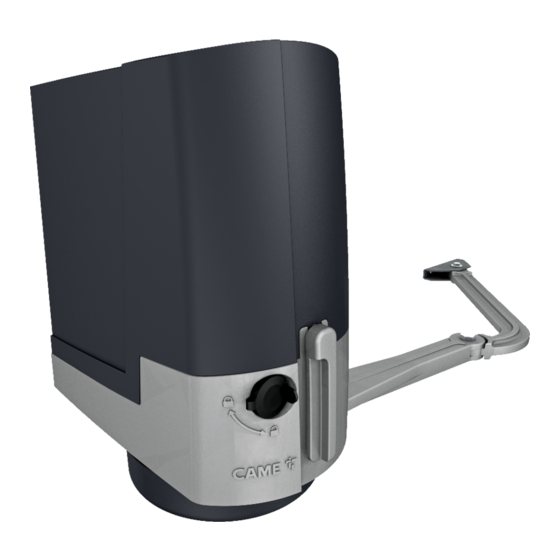
This symbol shows which parts to read carefully. ⚠ This symbol shows which parts describe safety issues ☞ This symbol shows which parts to tell users about. The measurements, unless otherwise stated, are in millimeters. DESCRIPTION Operator complete with control board, movement control and obstruction detecting device plus mechanical endstops for swing gates with leaves up to 2 m. -
Page 8: Description Of Parts
DESCRIPTION OF PARTS 1. Cover 10. Control-board supporting plate 2. Control-board protective cover 11. ZL65 control board 3. EMC02 card 12. Transmission arm protection 4. Post brace 13. Transmission arm 5. Gearmotor 14. Joint arm 6. Mechanical stops 15. Gate brace 7. -
Page 9: Technical Data
TECHNICAL DATA Model FTX20DGC - FTX20DLC Protection rating (IP) Power supply (V - 50/60 Hz) 230 AC Input voltage motor (V) 24 DC Max draw (A) Stand-by consumption (W) Stand-by consumption with the RGP1 (W) module Maximum power (W) Cycles/hour Operating temperature (°C) -
Page 10: Preliminary Checks
GENERAL INSTALLATION INDICATIONS PRELIMINARY CHECKS ⚠ Before beginning the installation, do the following: check that the gate structure is sturdy enough, the hinges work efficiently and that there is no friction between • the fixed and moving parts; if ground stops are not, or cannot be, fitted, use the supplied mechanical stops; •... -
Page 11: Installation
INSTALLATION ⚠ Only skilled, qualified staff must install this product. ⚠ The following illustrations are mere examples in that the space for fastening the operator and accessories varies depending on the installation area. It is up to the fitter, therefore, to choose the most suitable solution. ... - Page 12 Establish where you will fit the gate brace and measure where the gate-post brace will fit. Make sure to respect the quotas shown in the drawing and table. POST GATE BRACE BRACE FTX20DGC 150 min Leaf C max opening arc (°) 160 ÷...
- Page 13 FASTENING THE BRACES Marked the spots where the gate-post brace and gate brace will be fitted. The fastening measurements are listed in the paragraph titled CHECKING MEASUREMENTS AND APPLICATIVE DIMENSIONS. Drill the anchoring points, fit the dowels or use plugs that will hold fast the screws. ...
- Page 14 PREPARING AND FASTENING THE OPERATOR Remove the operator's cover in the following way: - open the lock protection cap, fit, the trilobe key into the lock and turn in counter-clockwise; - turn the release lever and loosen the screw that fastens the cover to the gearmotor; - push the cover back and lightly pull on its sides to lift it.
- Page 15 Fit the transmission arm to the shaft by using the slow-shaft washer and the bolt. UNI 6593 Ø 14 UNI 5739 M10x14 Fasten the driven-arm to the transmission arm by using the pin, the bolt and the washer. Ø 12 UNI 6593 Ø...
-
Page 16: Fastening The Mechanical Stops
⚠ Warning! If no end stops are fitted, you must fasten the stops. FASTENING THE MECHANICAL STOPS Release the gearmotor. When opening. Entirely open the gate leaf. Fit the stop under the casing, against the transmission arm and fasten it with the bolt. UNI 5931 M8x20 When closing. -
Page 17: Establishing The Limit-Switch Points
ESTABLISHING THE LIMIT-SWITCH POINTS With the gearmotor released and the gate-leaf closed, adjust the closing limit-switch grub screw by turning it clockwise or counterclockwise. Tighten the nut to fasten the grub-screw. Likewise, adjust the endstop by turning the endless screw on the other endstop. -
Page 18: Control Card
CONTROL CARD ⚠ Warning! Before working on the control panel, cut off the main power supply and, if present, remove any batteries. All wiring connections are quick-fuse protected. Fuses ZL65 - Line 2 A-F = 230 V - Accessories 2 A-F DESCRIPTION OF PARTS 11. -
Page 19: Electrical Connections
ELECTRICAL CONNECTIONS ⚠ The electrical cables must not touch any heated parts such as the motor, transformer, and so on. POWER SUPPLY 230 V AC 50/60 Hz 24 V AC/DC - max 40 W accessories power-supply output 24 V AC/DC control board power- supply input Trasformatore... -
Page 20: Electric Lock
ELECTRIC LOCK WARNING! An electric lock must be fitted to gate leaves exceeding 2.5 m in length when using irreversible gearmotors. Electric locks must always be fitted when using reversible gearmotors. Connect the electric lock to the transformer's 17 V output and to terminal 5 on the control board. WARNING! To access the transformer, you will need to remove the control board brace. -
Page 21: Control Devices
CONTROL DEVICES WARNING! For the system to work properly, before fitting any plug-in card, such as the AF or R800 one, you MUST CUT OFF THE MAINS POWER SUPPLY and, if present, disconnect any batteries. R700 / 800 To be able to snap in the cards into the dedicated connectors, raise... - Page 22 OPERATORS Operator installed on the left (outer view). BLUE (Default setting) BLACK BROWN 1 2 3P 7 10 TS 2 CX CY A B GND S1 GND A B 10 11 E 5 M1 N1 ENC1 M2 N2 ENC2 24 0 BLUE Operator installed on the right (inner view).
- Page 23 SAFETY DEVICES Photocells Configure contact CX or CY (NC), safety input for photocells. See CX input functions (Function F2) or CY (Function F3) in: - C1 reopening during closing. When the gate is closing, opening the contact triggers the inversion of movement until the gate is fully open again;...
- Page 24 Sensitive Safety Edges Configure contact CX or CY (NC), input for safety devices, such as sensitive safety edges, that comply with EN 12978 provisions. See CX input functions (Function F2) or CY (Function F3) in: - C7 reopening during closing. When the gate is closing, opening the contact triggers the inversion of movement until the gate is fully open again;...
- Page 25 CONNECTION WITH CAME REMOTE PROTOCOL (CRP) RS485 serial connection with RSE card via CRP (Came Remote Protocol). A B GND Fit the RSE card. UTP CAT 5 PROGRAMMING DESCRIPTION OF THE PROGRAMMING COMMANDS Display The ENTER key is for: The ESC button is for: - entering menus;...
-
Page 26: Functions Menu
FUNCTIONS MENU ⚠ When programming, the operator needs to be in stop mode. NC input – Gate stop that excludes any automatic closing; to resume movement, use the control device. The safety device should be fitted into Total stop [1-2] 1-2. - Page 27 It signals the gate status. The signaling device is connected to 10-5 or, alternatively, it enables the electric lock connected to the 17 V output of the transformer and to terminal 5. Output for gate open or for enabling the 0 = On when the barrier is open and moving (default) / 1= during electric lock openings it flashes intermittently each half second, and during...
- Page 28 10 = 10% of the maximum speed /…/ 50 = 50% of the maximum speed Slow-down speed (default) /.../ 60 = 60% of the maximum speed For the FTX20DGC-series gearmotors, the slow-down speed is set between 15% and 60%. Setting the gearmotors' speeds during calibration, calculated as a percentage.
- Page 29 Peripheral number 1 ----> 255 For setting the communication speed used in the CRP (Came Remote Protocol) connection system. COM speed 0 = 1200 Baud / 1 = 2400 Baud / 2 = 4800 Baud / 3 = 9600 Baud / 4 =...
- Page 30 1 = all (default) / 2 = Rolling Code / 3 = TWIN For setting the type of gearmotor fitted onto the system. Motor type 1 = SWN20 - SWN25 (default) / 2 = FA7024CB / 3 = FTX20DGC...
- Page 31 Test for checking the gearmotors' proper rotating directions (see the MOTORS TEST paragraph). Motors test OFF / ON Calibrating the gate travel (see the paragraph called CALIBRATING THE GATE TRAVEL). Travel calibration This function appears only is the Encoder function is activated. OFF / ON Attention! The default settings will be restored.
-
Page 32: Motors Test
MOTORS TEST Select A2. Press ENTER to confirm. ❶ Select ON. Press ENTER to confirm the motors test procedure. ❷ The following [---] characters will be displayed while waiting for a command. ❸ Keep pressed the > key and check whether the M2 second gearmotor's leaf performs an opening maneuver. ... -
Page 33: Travel Calibration
TRAVEL CALIBRATION Before calibrating the gate travel, position the gate half-way, check that the maneuvering area is clear of any obstruction and check that there are mechanical opening and closing stops. ⚠ The mechanical end-stops are obligatory. Important! During calibration, all safety devices will be disabled. Select A3. -
Page 34: Managing Users
MANAGING USERS When adding and deleting users, the flashing numbers appearing are those numbers that are available and usable to assign to a new user (max. 250 users). Before registering the users, make sure the AF radio card is plugged into the connector (see the paragraph called CONTROL DEVICES). - Page 37 DELETING SINGLE USERS Select U 2. Press ENTER to confirm. ❶ Select ON. Press ENTER to confirm the deletion procedure. ❷ Use the arrow keys select the number of the user you wish to delete. Press ENTER to confirm. ❸ ...
- Page 38 SAVING AND UPLOADING DATA WITH THE MEMORY ROLL For saving user and system configuration data with the Memory Roll, and for then reusing them on another control board, even on fitted into another system. WARNING! Fitting and extracting the Memory Roll must be done with the mains power disconnected. Fit the Memory Roll into the its corresponding connector on the control board.
- Page 39 ILLUSTRATION OF THE SLOW-DOWN POINTS AND END-STROKE AREAS The travel areas and slow-down and approach points are tested to comply with the parameters set forth by Technical Regulations EN 12445 and EN 12453 for impact force compatibility of moving gate leaves. = Movement area at normal speed.
-
Page 40: Final Operations
FINAL OPERATIONS FASTENING THE COVER Once the electrical connections and set up are done, fit the cover and fasten it using the supplied screws, then reposition the release lever. UNI 6955 3,9 x 9,5 FASTENING THE TRANSMISSION ARM PROTECTION Fit the protection under the operator and fasten it to the transmission arm using the screw. UNI 6955 3,9 x 13... -
Page 41: Error Message
ERROR MESSAGE The error messages are shown on the display. The travel calibration was interrupted when the STOP button was activated Calibrating the complete gate-travel Encoder broken Services test error Insufficient working time Closing obstruction Opening obstruction Maximum number of detected obstructions Serial communication error Incompatible transmitter error Wireless system error... - Page 42 ⚠ Warning! If no end stops are fitted, you must fasten the stops. FASTENING THE MECHANICAL STOPS Release the gearmotor. When opening. Entirely open the gate leaf. Fit the stop below the casing, against the transmission arm and fasten it by using the bolt. UNI 5931 M8x20 When closing.
- Page 43 OPERATORS Operator installed on the right (inner view). BLUE BLACK BROWN 1 2 3P 7 10 TS 2 CX CY A B GND S1 GND A B 10 11 E 5 M1 N1 ENC1 M2 N2 ENC2 24 0 BLUE Operator installed on the left (outer view).
-
Page 44: Dismantling And Disposal
DISMANTLING AND DISPOSAL ☞ CAME S.p.A. applies a certified Environmental Management System at its premises, which is compliant with the UNI EN ISO 14001 standard to ensure the environment is safeguarded. Please continue safeguarding the environment. At CAME we consider it one of the fundamentals of our operating and market strategies.
Need help?
Do you have a question about the FTX20DGC and is the answer not in the manual?
Questions and answers
HOW TO PROGRAM NEW REMOTES
To program new remotes for the CAME FTX20DGC:
1. Ensure the AF radio card is plugged into the connector.
2. Select user slot U1 (or any available number from 1 to 250). Press ENTER to confirm.
3. Select a command to associate with the user:
- 1 = step-step (open-close)
- 2 = sequential (open-stop-close-stop)
- 3 = open
- 4 = partial opening
Press ENTER to confirm.
4. A number between 1 and 250 will flash. During this time, send the code from the new remote or control device.
5. Record the new user in the "REGISTERED USERS LIST".
This answer is automatically generated