CAME FROG Installation Manual
Swing-gate operator
Hide thumbs
Also See for FROG:
- Installation manual (49 pages) ,
- Installation manual (12 pages) ,
- Installation manual (16 pages)

Related Manuals for CAME FROG


Summary of Contents for CAME FROG
- Page 1 Automazioni per cancelli a battente FA01569M04 FROG FROG-A24 FROG-A24E Italiano EN English MANUALE DI INSTALLAZIONE Français RU Русский...
-
Page 3: Avvertenze Generali Per L'installatore
Direttiva Macchine 2006/42/CE ed agli standard tecnici armonizzati di riferimento sono identificati nel catalogo generale dei prodotti CAME oppure nel sito internet www.came.com. • Durante tutte le fasi dell’installazione assicurarsi di operare fuori tensione. • Verificare che il range di temperature indicato sia adatto al luogo di installazione. - Page 4 • Eventuali rischi residui devono essere segnalati mediante opportuni pittogrammi posizionati bene in vista e devono essere spiegati all’utilizzatore finale. • Posizionare bene in vista la targa identificativa della macchina al completamento dell’installazione. • Se il cavo di alimentazione è danneggiato, deve essere sostituito dal produttore o dal servizio di assistenza tecnica autorizzato, o comunque da personale debitamente qualificato, per evitare ogni rischio.
-
Page 5: Descrizione Delle Parti
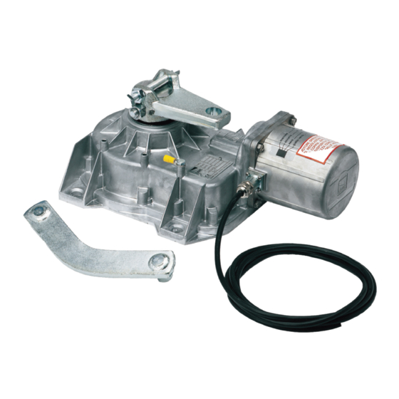
Questo simbolo indica cosa comunicare all’utente. Le misure, se non diversamente indicato, sono in millimetri. Descrizione FROG-A24 Motoriduttore interrato 24 V irreversibile con fermo anta in chiusura regolabile per cancelli a battente con ante fino a 3,5 m e 400 kg di peso. FROG-A24E Motoriduttore interrato 24 V irreversibile con encoder e fermo anta in chiusura regolabile per cancelli a battente con ante fino a 3,5 m e 400 kg di peso. -
Page 6: Limiti Di Impiego
Per i collegamenti di prodotti non contemplati in questo manuale fa fede la documentazione allegata ai prodotti stessi. Per il collegamento dell'Encoder, utilizzare un cavo tipo FRORPU 3 x 0,5mm2 o un cavo fornito da CAME su richiesta (codice articolo 801XA-0020). -
Page 7: Installazione
INSTALLAZIONE Le seguenti illustrazioni sono solo esempi in quanto lo spazio per il fissaggio dell’automazione e degli accessori varia a seconda della zona di installazione. Spetta all’installatore scegliere la soluzione più adatta. I disegni si riferiscono al motoriduttore installato a destra. Operazioni preliminari Le operazioni preliminari all’installazione riguardano la posa della cassa di fondazione e il fissaggio dei dispositivi di sblocco. - Page 8 Lubrificare la leva di trasmissione. Inserire la leva di trasmissione come indicato nei disegni. Determinazione dei punti di finecorsa con finecorsa meccanici Aprire manualmente l'anta fino al punto desiderato. L'apertura massima dell'anta è pari a 110°. Svitare la vite di regolazione del punto di finecorsa di apertura fino al contatto con la cassa di fondazione. Stringere il dado per bloccare la posizione della vite.
-
Page 9: Collegamenti Elettrici
COLLEGAMENTI ELETTRICI Prima di intervenire sul quadro di comando, togliere la tensione di linea e, se presenti, scollegare le batterie. Motoriduttore con Encoder Cavo bianco Cavo per l'alimentazione Cavo marrone Cavo dell'Encoder Cavo verde Cavo 801XA-0020 M1 N1 E1 + E - M2 N2 E2 + E -... - Page 10 Motoriduttore senza Encoder Cavo marrone Cavo per l'alimentazione Cavo blu Cavo per il rallentamento in apertura Cavo per il rallentamento in chiusura M1 N1 E1 M2 N2 E2 2 FA1 FC1 FA2 FC2...
- Page 11 RA1 RC1 C RA2 RC2 C FA1 FC1 C FA2 FC2 C M1 N1 M2 N2 RA1 RC1 C RA2 RC2 C FA1 FC1 C FA2 FC2 C M1 N1 M2 N2...
- Page 12 Determinazione dei punti di rallentamento* Solo per FROG-A24 Dare un comando di apertura e fermare le ante a circa 600 mm dalla battuta di arresto. Posizionare i microinterruttori magnetici come indicato nelle immagini. Dare un comando di chiusura e fermare le ante a circa 600 mm dalla battuta di arresto.
-
Page 13: Operazioni Finali
OPERAZIONI FINALI APERTURA VERSO L'ESTERNO Di seguito, sono descritte le operazioni diverse rispetto all'installazione standard. Preparazione del motoriduttore Inserire la vite di regolazione del punto di finecorsa di chiusura nel braccio del motoriduttore. Motoriduttore installato a sinistra Motoriduttore installato a destra... - Page 14 Determinazione dei punti di rallentamento* Solo per FROG-A24 Dare un comando di apertura e fermare le ante a circa 600 mm dalla battuta di arresto. Posizionare i microinterruttori magnetici come indicato nelle immagini. Dare un comando di chiusura e fermare le ante a circa 600 mm dalla battuta di arresto.
- Page 16 CAME S.p.A. Via Martiri della Libertà, 15 31030 Dosson di Casier Treviso - Italy Tel. (+39) 0422 4940 Fax (+39) 0422 4941...
- Page 17 Swing-gate operator FA01569-EN FROG FROG-A24 FROG-A24E INSTALLATION MANUAL EN English...
- Page 19 Machinery Directive (2006/42/EC) and with the reference harmonised technical standards are specified in the general CAME product catalogue or on the website www.came.com. • Make sure the mains power supply is disconnected during all installation procedures. • Check that the temperature ranges given are suitable for the installation site. • When excavating to lay the foundation box, ensure there is sufficient drainage to prevent water from stagnating inside it.
- Page 20 • Any residual risks must be indicated clearly with proper signage affixed in visible areas, and explained to end users. • Put the machine’s ID plate in a visible place when the installation is complete. • If the power supply cable is damaged, it must be immediately replaced by the manufacturer or by an authorised technical assistance centre, or in any case, by qualified staff, to prevent any risk.
-
Page 21: Intended Use
This symbol shows what to tell users. The measurements, unless otherwise stated, are in millimetres. Description FROG-A24 Underground irreversible 24 V gearmotor with adjustable leaf-stop during closing, for swing gates with leaves up to 3.5 m in length and 400 kg in weight. FROG-A24E Underground irreversible 24 V gearmotor with encoder and adjustable leaf-stop during closing, for swing gates with leaves up to 3.5 m in length and 400 kg in weight. -
Page 22: Usage Limitations
For multiple, sequential loads along the same line, recalculate the values in the table according to the actual power draw and distances. For information on connecting products not covered in this manual, please see the documentation accompanying the products themselves. To connect the encoder, use a FRORPU 3 x 0.5 mm² cable or a cable supplied by CAME on request (item code 801XA-0020). -
Page 23: Installation
INSTALLATION The following illustrations are examples only. The space available for fitting the operator and accessories varies depending on the area where it is installed. It is up to the installer to find the most suitable solution. The drawings refer to the right-side gearmotor. Preliminary operations The preliminary operations for installation concern the foundation box installation and the release devices fastening. - Page 24 Lubricate the transmission lever. Fit the transmission lever as shown in the drawings. Determining the travel end points with mechanical limit switches Manually open the leaf to the desired point. The leaf maximum opening is 110°. Unscrew the opening limit-switch point adjustment screw until it touches the foundation box. Tighten the nut to lock the screw into position.
-
Page 25: Electrical Connections
ELECTRICAL CONNECTIONS Before working on the control panel, disconnect the mains power supply and remove the batteries, if any. Gear motor with encoder White cable Power supply cable Brown cable Encoder cable Green cable 801XA-0020 cable M1 N1 E1 + E - M2 N2 E2 + E -... - Page 26 Gearmotor without Encoder Brown cable Power supply cable Blue cable Cable for slowing down during opening Cable for slowing down during closing M1 N1 E1 M2 N2 E2 2 FA1 FC1 FA2 FC2...
- Page 27 RA1 RC1 C RA2 RC2 C FA1 FC1 C FA2 FC2 C M1 N1 M2 N2 RA1 RC1 C RA2 RC2 C FA1 FC1 C FA2 FC2 C M1 N1 M2 N2...
- Page 28 Establishing the slow-down points* Only for the FROG-A24 Give an opening command and stop the leaves at about 600 mm from the strike plate. Position the magnetic microswitches as shown in the images. Give an closing command and stop the leaves at about 600 mm from the strike plate.
-
Page 29: Final Operations
FINAL OPERATIONS OUTWARDS OPENING The operations other than the standard installation are described below. Setting up the gearmotor Insert the closing limit-switch point adjustment screw into the gearmotor arm. Gearmotor installed on the left Gearmotor installed on the right... - Page 30 Establishing the slow-down points* Only for the FROG-A24 Give an opening command and stop the leaves at about 600 mm from the strike plate. Position the magnetic microswitches as shown in the images. Give an closing command and stop the leaves at about 600 mm from the strike plate.
- Page 32 CAME S.p.A. Via Martiri della Libertà, 15 31030 Dosson di Casier Treviso - Italy Tel. (+39) 0422 4940 Fax (+39) 0422 4941...
- Page 33 Automatismes pour portails battants FA01569-FR FROG FROG-A24 FROG-A24E MANUEL D'INSTALLATION Français...
- Page 35 2006/42/CE et les normes techniques harmonisées de référence sont identifiés dans le catalogue général des produits CAME ou sur le site www.came.com. • S’assurer, durant toutes les phases d’installation, que l’automatisme est bien hors tension. • S'assurer que la température du lieu d'installation correspond à celle indiquée sur l'automatisme. •...
- Page 36 • Les éventuels risques résiduels doivent être signalés à l'utilisateur final par le biais de pictogrammes spécifiques bien en vue qu’il faudra lui expliquer. • Au terme de l’installation, appliquer la plaque d’identification de la machine dans une position bien en vue. • Si le câble d'alimentation est endommagé, son remplacement doit être effectué par le producteur, ou par son service d'assistance technique agréé, ou par une personne dûment qualifiée afin de prévenir tout risque.
-
Page 37: Utilisation Prévue
Ce symbole indique ce qui doit être communiqué à l'utilisateur. Les dimensions sont exprimées en millimètres, sauf indication contraire. Description FROG-A24 Motoréducteur irréversible enterré 24 V avec butée réglable du vantail en fermeture pour portails battants jusqu'à 3,5 m et 400 kg par vantail. FROG-A24E Motoréducteur irréversible enterré... -
Page 38: Limites D'utilisation
Pour les connexions de produits non indiqués dans ce manuel, considérer comme valable la documentation jointe à ces derniers. Pour connecter l’encodeur, utiliser un câble type FRORPU 3 x 0,5 mm² ou un câble fourni par la société CAME (code article 801XA-0020). -
Page 39: Opérations Préliminaires
INSTALLATION Les illustrations suivantes ne sont que des exemples étant donné que l'espace pour la fixation de l'automatisme et des accessoires varie en fonction de la zone d'installation. C'est donc l'installateur qui doit choisir la solution la plus indiquée. Les dessins se réfèrent au motoréducteur installé à droite. Opérations préliminaires Les opérations préalables à... - Page 40 Lubrifier le levier de transmission. Installer le levier de transmission comme indiqué sur les dessins. Définition des points de fin de course avec butées de fin de course mécaniques Ouvrir manuellement le vantail jusqu'à la position souhaitée. L'ouverture maximale du vantail est de 110°. Dévisser la vis de réglage du point de fin de course de fermeture jusqu'au contact avec le caisson de fondation.
-
Page 41: Branchements Électriques
BRANCHEMENTS ÉLECTRIQUES Avant d'intervenir sur l'armoire de commande, mettre hors tension et déconnecter les éventuelles batteries. Motoréducteur avec Encodeur Câble blanc Câble d'alimentation Câble marron Câble de l’encodeur Câble vert Câble 801XA-0020 M1 N1 E1 + E - M2 N2 E2 + E -... - Page 42 Motoréducteur sans encodeur Câble marron Câble d'alimentation Câble bleu Câble pour le ralentissement en ouverture Câble pour le ralentissement en fermeture M1 N1 E1 M2 N2 E2 2 FA1 FC1 FA2 FC2...
- Page 43 RA1 RC1 C RA2 RC2 C FA1 FC1 C FA2 FC2 C M1 N1 M2 N2 RA1 RC1 C RA2 RC2 C FA1 FC1 C FA2 FC2 C M1 N1 M2 N2...
- Page 44 Détermination des points de ralentissement* Uniquement pour FROG-A24 Envoyer une commande d'ouverture et arrêter les vantaux à environ 600 mm de la butée d'arrêt. Positionner les micro-interrupteurs magnétiques comme indiqué sur les images. Envoyer une commande de fermeture et arrêter les vantaux à environ 600 mm de la butée d'arrêt.
-
Page 45: Opérations Finales
OPÉRATIONS FINALES OUVERTURE VERS L'EXTÉRIEUR Les opérations décrites ci-après sont différentes par rapport à l'installation standard. Préparation du motoréducteur Insérer la vis de réglage du point de fin de course de fermeture dans le bras du motoréducteur. Motoréducteur installé à gauche Motoréducteur installé... - Page 46 Détermination des points de ralentissement* Uniquement pour FROG-A24 Envoyer une commande d'ouverture et arrêter les vantaux à environ 600 mm de la butée d'arrêt. Positionner les micro-interrupteurs magnétiques comme indiqué sur les images. Envoyer une commande de fermeture et arrêter les vantaux à environ 600 mm de la butée d'arrêt.
- Page 48 CAME S.p.A. Via Martiri della Libertà, 15 31030 Dosson di Casier Treviso - Italy Tél. (+39) 0422 49 40 Fax (+39) 0422 49 41...
- Page 49 Автоматика для распашных ворот FA01569-RU FROG FROG-A24 FROG-A24E РУКОВОДСТВО ПО МОНТАЖУ Русский...
- Page 51 оборудования 2006/42/CE и гармонизированным техническим стандартам, указаны в общем каталоге продукции CAME или на сайте www.came.com. • Убедитесь в отсутствии напряжения перед каждым этапом монтажных работ. • Убеди- тесь в том, что указанный диапазон температур соответствует температуре окружающей среды в месте установки. •...
- Page 52 • О всех остаточных рисках необходимо предупреждать посредством специальных символов, расположив их на видном месте, и доходчиво объяснить их конечному пользователю оборудования. • По завершении установки прикрепите к обо- рудованию паспортную табличку на видном месте. • Во избежание риска замена поврежденного кабеля питания должна выполняться...
-
Page 53: Условные Обозначения
Этот символ обозначает раздел, предназначенный для ознакомления конечного пользователя. Все размеры приведены в мм, если не указано иное. Описание FROG-A24 Самоблокирующийся привод для подземной установки 24 В с регулируемым упором при закрывании для распашных ворот со створками длиной до 3,5 м и массой до 400 кг. - Page 54 с учетом реальных показателей потребления и фактических расстояний. При подключении устройств, не рассматриваемых в этой инструкции, следует руководствоваться технической документацией на соответствующее изделие. Для подключения энкодера используйте кабель типа FRORPU 3 x 0,5 мм2 или кабель, предоставляемый компанией CAME (артикул изделия 801XA- 0020).
-
Page 55: Предварительные Работы
МОНТАЖ Приведенные ниже рисунки носят иллюстративный характер, поскольку пространство для крепления автоматики и дополнительных принадлежностей может изменяться от случая к случаю. Выбор наиболее подходящего решения должен осуществляться монтажником во время установки. На рисунках показан монтаж привода справа. Предварительные работы К подготовительным работам перед монтажом относятся установка монтажного основания и закрепление устройств разблокировки. См. руководства по... - Page 56 Смажьте рычаг передачи. Вставьте рычаг передачи, как показано на рисунке. Определение крайних положений с механическими концевыми выключателями Откройте створку вручную до желаемого положения. Максимальный угол открывания створки составляет 110°. Открутите винт регулировки конечной точки открывания до соприкосновения с фундаментной коробкой. Затяните...
-
Page 57: Электрические Подключения
ЭЛЕКТРИЧЕСКИЕ ПОДКЛЮЧЕНИЯ Перед началом работ по эксплуатации, ремонту, настройке и регулировке блока управления отключите сетевое электропитание и/или отсоедините аккумуляторы. Мотор-редуктор с энкодером Белый провод Кабель электропитания Коричневый провод Кабель энкодера Зеленый кабель Кабель 801XA-0020 M1 N1 E1 + E - M2 N2 E2 + E -... - Page 58 Привод без энкодера Коричневый провод Кабель электропитания Синий провод Кабель системы замедления при открывании Кабель системы замедления при закрывании M1 N1 E1 M2 N2 E2 2 FA1 FC1 FA2 FC2...
- Page 59 RA1 RC1 C RA2 RC2 C FA1 FC1 C FA2 FC2 C M1 N1 M2 N2 RA1 RC1 C RA2 RC2 C FA1 FC1 C FA2 FC2 C M1 N1 M2 N2...
- Page 60 Регулировка точек начала замедления* Только для FROG-A24 Отправьте команду на открывание и остановите створки приблизительно в 600 мм от механического упора. Расположите магнитные микровыключатели, как показано на рисунках. Отправьте команду на закрывание и остановите створки приблизительно в 600 мм от механического упора.
-
Page 61: Заключительные Работы
ЗАКЛЮЧИТЕЛЬНЫЕ РАБОТЫ ОТКРЫВАНИЕ НАРУЖУ Далее описываются процедуры стандартного монтажа. Подготовка привода Вставьте винт регулировки конечной точки закрывания в рычаг привода. Привод, установленный слева Привод, установленный справа... - Page 62 Регулировка точек начала замедления* Только для FROG-A24 Отправьте команду на открывание и остановите створки приблизительно в 600 мм от механического упора. Расположите магнитные микровыключатели, как показано на рисунках. Отправьте команду на закрывание и остановите створки приблизительно в 600 мм от механического упора.
- Page 64 CAME S.p.A. Via Martiri della Libertà, 15 31030 Доссон-ди-Казьер Treviso - Italy (Италия) Тел.: (+39) 0422 4940 Факс: (+39) 0422 4941...
Need help?
Do you have a question about the FROG and is the answer not in the manual?
Questions and answers