CAME FROG Series Installation Manual
In-ground operator for swing gates
Hide thumbs
Also See for FROG Series:
- Installation manual (49 pages) ,
- Installation instructions manual (32 pages) ,
- Manual (16 pages)
Table of Contents
Advertisement
Quick Links
Advertisement
Table of Contents

Subscribe to Our Youtube Channel
Related Manuals for CAME FROG Series


Summary of Contents for CAME FROG Series
- Page 1 IN-GROUND OPERATOR FOR SWING GATES FROG SERIES INSTALLATION MANUAL FROG J...
-
Page 2: Legend Of Symbols
For intensive use and condominiums: max weight of the gate 200kg, and max length 1.8m. 3 Reference Standards The company: CAME Cancelli Automatici s.p.a. is ISO 9001:2000 quality certified; is has also obtained the ISO 14001 environ- mental safeguarding certification. Came engineers and manufactures all of its products in Italy. -
Page 3: Description Of Parts
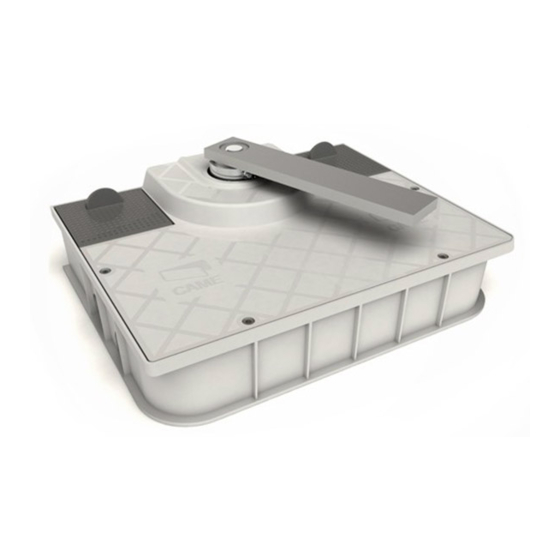
4.3 Description of parts FROG J OPERATO 1) Gate pin-housing ring 2) Gearmotor pin-housing ring 3) Gearmotor mobile ring 4) Endstop adjustment set screw 5) Release group 6) Cover 7) Operator 8) In-ground case 9) Custom key for release group 4.4 Dimensions (mm) -
Page 4: Installation
5 Installation Installation must be carried out by expert qualified personnel and in full compliance with current regulations. 5.1 Preliminary checks Before installing, do the following: • Make sure you have a suitable omnipolar cut-off device with contacts more than 3 mm apart, and independent (sectioned off) power supply. -
Page 5: Standard Installation
5.3 Cable list and minimum thickness Connections Type of cable Length of cable 1 < 10 m L. of cable 10 < 20 m L. of cable 20 < 30 m Control panel power supply 230 3F 3G x 1,5 mm 3G x 2,5 mm 3G x 4 mm Motor power supply 24V... - Page 6 5.5 Preparing for the foundation casing The following illustrations are only examples, given that the space available for anchoring the operator and accessories may vary from gate to gate. It is up to the installer, thus, to choose the most suitable solution. N.B: illustration view: left side, inside view.
-
Page 7: Installing The Unit
5.6 Installing the unit N.B.: view of illustrations: outer side (to simplify the description of the moun- ting phases) - Insert the releases into the in-ground box and anchor them using the supplied screws. - Assemble the transmission arm with the pin-housing ring to the stuffi ng box, anchor them using the (M6x16) set screws and nuts. Warning: the threaded holes for inserting the (m10x90) adjustment set screw of the gate pin-housing ring is to be positioned opposite the threaded hole of the gearmotor pin-housing ring.posizionato dalla parte opposta al foro fi... - Page 8 - Mount the gate leaf by only inserting the top hinge. Check that the gate leaf opens and closes easily. Bolt into place using the proper bolts or carefully weld the gate leaf to the transmission arm. - Insert the gearmotor into the in-ground box and anchor it using bolts and washers.
-
Page 9: Adjusting The Mechanical Endstops
Set the lever of the release group to the gearmotor. 5.7 Adjusting the mechanical endstops - Before tightening the set screws to adjust the opening and closing of the gate, release the gearmotors (see paragraph for manual releasing). Procedure for adjusting the closing: turn the M10x90 (1) set screw clockwise or counter clockwise; lock the nut so that it is opposite the thread (2). - Page 10 - After making the necessary adjustments and electrical connections (see following chapter), place the cover onto the box and screw it down using the supplied cylinder-head screws. Ø4,8x19 5.7 Manual release of the gearmotor - Lift the cover to the release group, insert and turn the key.Turn the release handle clockwise. - Close the door before manually moving the gate.
-
Page 11: Connecting To The Control Panel
6 Connecting to the control panel When making electrical connections, use the pit the shunt boxes. For further instructions concerning functions and adjustments, consult the control panels technical documentation. 1) Control panel 2) Left gearmotor 3) Right gearmotor 4) Shunt box 5) Junction pit ZL90 Control panel BLUE... -
Page 12: Safety Instructions
7 Safety instructions Important safety instructions This product must only be employed for its originally intended use. Any other use is wrong and potentially dangerous. The manufacturer cannot be held liable for any damages resulting from wrongful, erroneous or negligent uses. Avoid working close to the hinges or other moving mechanical parts. -
Page 13: Periodic Maintenance
8 Maintenance 8.1 Periodic maintenance Periodic maintenance to be carried out by the end-user is as follows: wipe clean the glass surface of the photocel- ls; check that the safety devices work properly; remove any obstructions. We suggest checking the state of lubrication and tightness of the anchoring screws on the operator. To check the efficiency of the safety devices, move an object in front of the photocells when gate is closing. -
Page 14: Extraordinary Maintenance
Periodic maintenance log (for end-user) (every 6 moths) Date Notes Segnature 8.3 Extra-ordinary maintenance The following table serves to note down any extraordinary maintenance, repairs or improvements performed by spe- cialised firms. N.B.: Any extraordinary maintenance must be performed by specialised technicians. Extra-ordinary maintenance log Installer’s stamp Operator name... -
Page 15: Demolition And Disposal
UNI EN ISO 14001 standard to ensure environmental protection. Please continue our efforts to protect the environment—which CAME considers one of the cardinal elements in the develop- mentof its operational and market strategies—simply by observing brief recommendations as regards disposal: DISPOSAL OF PACKAGING The packaging components (cardboard, plastic, etc.) are all classifiable as solid urban waste products and may be disposed of... - Page 16 CAME UNITED KINGDOM LTD UNIT 3, ORCHARD BUSINESS PARK TOWN STREET, SANDIACRE NOTTINGHAM - NG10 5BP - U.K. Tel 0044 115 9210430 Fax 0044 115 9210431...
Need help?
Do you have a question about the FROG Series and is the answer not in the manual?
Questions and answers