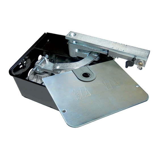
CAME FROG Series Installation Manual
Swing-gate operator
Hide thumbs
Also See for FROG Series:
- Installation manual (49 pages) ,
- Installation instructions manual (32 pages) ,
- Manual (16 pages)
Summary of Contents for CAME FROG Series
- Page 1 Swing-gate operator FA01302-EN FROG FROG-A24 FROG-A24E INSTALLATION MANUAL EN English...
- Page 3 GENERAL PRECAUTIONS FOR INSTALLERS Important safety instructions. Follow all of these instructions. Improper installation can cause serious bodily harm. Before continuing, also read the general precautions for users. Use this product only for its specifically intended use. Any other use is hazardous. The manufacturer can not be held liable for any damage caused by improper, unreasonable, and erroneous use.
- Page 4 Any residual risks must be indicated clearly with proper signage affixed in visible areas. All of which must be explained to end users. Fit, in plain sight, the machine's ID plate when the installation is complete. If the power-supply cable is damaged, it must be immediately replaced by the manufacturer or by an authorized technical assistance center, or in any case, by qualified staff, to prevent any risk.
-
Page 5: Intended Use
PRODUCT DATA AND INFORMATION Legend This symbol shows which parts to read carefully. This symbol shows which parts describe safety issues This symbol shows which parts to tell users about. The measurements, unless otherwise stated, are in millimeters. Description Irreversible geared-motor for swing gates up to 3.5 m in length per leaf, with adjustable leaf-closing. Irreversible geared-motor for swing gates up to 3.5 m in length per leaf, with adjustable leaf-closing. - Page 6 Dimensions Limits to use It is always advisable to install an electric lock, to ensure reliable closure of the gate. The installation of an electric lock is mandatory in the case of irreversible gearmotors and with gate leaves longer than 2.5 m. MODELS FROG-A24 FROG-A24E...
-
Page 7: Installation
INSTALLATION The following illustrations are just examples, as the space available for fitting the operator and accessories varies depending on the area where it is installed. The drawings refer to the right-side gearmotor. Preliminary operations The preliminary operations for installation concern the foundation box installation and the release devices fastening. Refer to the installation manuals for these products. - Page 8 Lubricate the transmission lever. Fit the transmission lever as shown in the drawings. Establishing the travel end points with mechanical limit-switches Manually open the leaf to the desired point. The leaf maximum opening is 110°. Unscrew the opening limit-switch point adjustment screw until it touches the foundation box. Tighten the nut to lock the screw into position.
-
Page 9: Electrical Connections
ELECTRICAL CONNECTIONS Before working on the control panel, cut off the mains power supply and remove the batteries, if any. Gear motor with Encoder 1 White cable Power supply cable 2 Brown cable Encoder cable 3 Green cable 801XA-0010 cable 4 Earthing braid 5 Yellow-green cable M1 N1 E1 + E - M2 N2 E2 + E -... - Page 10 Gearmotor without Encoder 1 Brown cable Power supply cable 2 Blue cable Cable for slowing down during opening Cable for slowing down during closing M1 N1 E1 M2 N2 E2 2 FA1 FC1 FA2 FC2...
- Page 11 RA1 RC1 C RA2 RC2 C FA1 FC1 C FA2 FC2 C M1 N1 M2 N2 RA1 RC1 C RA2 RC2 C FA1 FC1 C FA2 FC2 C M1 N1 M2 N2...
- Page 12 Establishing the slow-down points * * Only for the FROG-A24 Give an opening command and stop the leaves at about 600 mm from the strike plate. Position the magnetic microswitches as shown in the images. Give an closing command and stop the leaves at about 600 mm from the strike plate. Position the magnetic microswitches as shown in the images.
-
Page 13: Final Operations
FINAL OPERATIONS OUTWARDS OPENING The operations other than the standard installation are described below. Setting up the gearmotor Insert the closing limit-switch point adjustment screw into the gearmotor arm. Gearmotor installed on the left Gearmotor installed on the right... - Page 14 Establishing the slow-down points * * Only for the FROG-A24 Give an opening command and stop the leaves at about 600 mm from the strike plate. Position the magnetic microswitches as shown in the images. Give an closing command and stop the leaves at about 600 mm from the strike plate. Position the magnetic microswitches as shown in the images.
-
Page 16: Dismantling And Disposal
DISMANTLING AND DISPOSAL CAME S.p.A. employs an Environmental Management System at its premises. This system is certified and compliant with the UNI EN ISO 14001 regulation standard to ensure that the environment is respected and safeguarded. Please continue safeguarding the environment. At CAME we consider it one of the fundamentals of our operating and market strategies.


Need help?
Do you have a question about the FROG Series and is the answer not in the manual?
Questions and answers