CAME FROG Series Installation Manual

Automation system for swing gates
Hide thumbs Also See for FROG Series:

Advertisement

Quick Links

AUTOMATION SYSTEM FOR SWING GATES
FROG
SERIES
INSTALLATION MANUAL
SUPERFROG

Advertisement

Table of Contents
loading

Summary of Contents for CAME FROG Series

  • Page 1 AUTOMATION SYSTEM FOR SWING GATES FROG SERIES INSTALLATION MANUAL SUPERFROG...
  • Page 2: Reference Standards

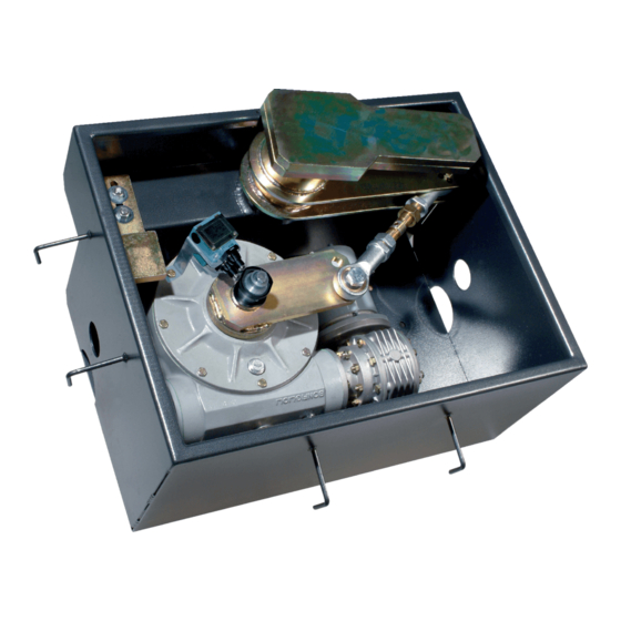
    4 Description 4.1 Automation SUPERFROG was designed and manufactured by CAME CANCELLI AUTOMATICI S.p.A. and is compliant with the safety regu- lations in force. Guaranteed 24 months if not tampered with. The automation system is composed of a foundation box, a gearmotor – and a series of arms.
  • Page 3: Description Of The Parts

    4.3 Description of the parts GEARMOTOR UNIT 1) Tie rod 2) Motor support assembly 3) Gearmotor 4) Cover 5) Foundation box 6) Upper arm assembly 7) Arm assembly 8) Sleeve bearing 9) Hole cover for case 10) Bracket for case 4.4 Dimensions Measurements in mm...
  • Page 4: Installation

    5 Installation The installation must be carried out by export, qualified personnel in total compliance with the norms in effect. 5.1 Preliminary checks Before proceeding with the installation, it is necessary to: • Provide for a suitable omnipolar disconnection device with contacts more than 3 mm apart, and independent (sectioned off) power supply;...
  • Page 5 5.3 Cable list and minimum thickness Connections Type of cable Length of cable 1 < 10 m L. of cable 10 < 20 m L. of cable 20 < 30 m 230/400V 3F power supply 4G x 1,5 mm 4G x 2,5 mm 4G x 4 mm 230/400V 3F motor power supply 4G x 1 mm...
  • Page 6 5.4 Preparing the foundation box The following applications are only examples, as the space required for unit installation and the accessories vary de- pending on dimensions and therefore it is up to the installer to select the best solution. Note: the following sketches show how to install the right-hand foundation box (CD). - Dig a pit to place the foundation box into, set up the required cable boxes and corrugated conduits –...
  • Page 7 - Lubricate the pinion of the foundation box, the sleeve bearing, the arm assembly and the upper arm assembly. Follow the diagrams to assemble properly. Arm assembly Upper arm assembly Sleeve bearing Pinion - Place the gate leaf above the upper arm assembly making sure that the hinge is secured properly. Properly weld the gate leaf to the upper arm assembly.
  • Page 8: Installing The Motor Unit

    5.5 Installing the motor unit N.B. the diagrams that follow show an outer view so as to make the (MD) right-hand gearmotor installation more intuitive. - Place the gearmotor into the foundation box and fasten it with nuts and washers using the crow’s foot wrench supplied and the proper ratchet wrench.
  • Page 9 - When the gate leaf is in the closed position, adjust the box bracket until it stops against with the motor arm assembly and fasten it. - Rest the cover on top of the foundation box, fi x the hole cover into place and insert the cap into the cover. UNI 5933 M6x12 Cover Hole cover for case...
  • Page 10 6 Connecting up to the control panel Electrical connection for 400V gearmotor. When performing electrical connections, it is always advisable ZA2S Control panel to do so using the branching pit or the cable boxes. For further guidance on functions and settings, read the technical documentation of the control panel.
  • Page 11: Maintenance

    UNI EN ISO 14001 standard to ensure environmental protection. Please continue our efforts to protect the environment—which CAME considers one of the cardinal elements in the development of its operational and market strategies—simply by observing brief recommendations as regards disposal: DISPOSAL OF PACKAGING –...
  • Page 12 CAME UNITED KINGDOM LTD UNIT 3, ORCHARD BUSINESS PARK TOWN STREET, SANDIACRE NOTTINGHAM - NG10 5BP - U.K. Tel 0044 115 9210430 Fax 0044 115 9210431...

This manual is also suitable for:

Superfrog

Table of Contents