
Related Manuals for CAME FTL Series


Summary of Contents for CAME FTL Series
- Page 1 Automazione per cancelli a battente FA00995M04 IT Italiano FTL20DGC EN English FR Français MANUALE D'INSTALLAZIONE RU Pусский...
- Page 3 è stato espressamente studiato. Ogni altro uso è da considerarsi pericoloso. Came S.P.A. non è responsabile per eventuali danni causati da usi impropri, erronei ed irragionevoli. • Il prodotto oggetto di questo manuale è...
- Page 4 selettore transponder, ecc.), i dispositivi di comando ad azione mantenuta devono essere installati a un’altezza di almeno 1,5 m e in un luogo non accessibile al pubblico • Il produttore declina ogni responsabilità per l’impiego di prodotti non originali; questo implica inoltre la decadenza della garanzia •...
- Page 5 LEGENDA Questo simbolo indica parti da leggere con attenzione. ⚠ Questo simbolo indica parti riguardanti la sicurezza. ☞ Questo simbolo indica cosa comunicare all’utente. Le misure, se non diversamente indicato, sono in millimetri. DESCRIZIONE Automazione completa di scheda elettronica, dispositivo per il controllo del movimento e rilevazione dell'ostacolo e finecorsa meccanici per cancelli a battente fino a 2 m per anta.
-
Page 6: Table Of Contents
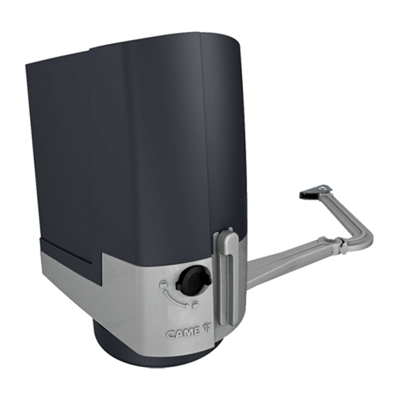
Dimensioni Descrizione delle parti 1. Coperchio 2. Coperchio di protezione scheda 3. Scheda EMC02 4. Staffa pilastro 5. Motoriduttore 6. Fermo meccanico 7. Leva di sblocco 8. Serratura 9. Supporto porta-schede 10. Porta-schede 11. Scheda elettronica 12. Protezione braccio di trasmissione 13. - Page 7 Impianto tipo 1. Automazione 2. Motoriduttore 3. Lampeggiatore 4. Selettore a chiave 5. Fotocellule 6. Colonnina per fotocellule 7. Battuta di arresto 8. Pozzetto di derivazione 9. Trasmettitore...
- Page 8 INDICAZIONI GENERALI PER L'INSTALLAZIONE Tipo cavi e spessori minimi lunghezza cavo Collegamento < 20 m 20 < 30 m Alimentazione quadro 3G x 1,5 mm 3G x 2,5 mm Motoriduttore 24 V DC 3 x 1,5 mm 3 x 2,5 mm Lampeggiatore 2 x 0,5 mm Dispositivi di comando...
-
Page 9: Staffa Pilastro 14
Operazioni preliminari Predisporre scatole di derivazione e tubi corrugati necessari per i collegamenti provenienti dal pozzetto di derivazione. Il numero di tubi dipende dal tipo di impianto e dagli accessori previsti. È necessario predisporre almeno 2 tubi corrugati dove viene installata l’automazione ( sull'anta che apre per prima). - Page 10 Fissaggio delle staffe Segnare i punti di fi ssaggio della staff a pilastro e della staff a cancello. Le quote di fi ssaggio sono indicate nel paragrafo VERIFICHE QUOTE E DIMENSIONI DI APPLICAZIONE. Forare i punti di fi ssaggio, inserire i tasselli o utilizzare degli inserti adeguati per la tenuta delle staff e. ...
-
Page 11: Uni 5931 M8 X
Inserire il motoriduttore nella staffa pilastro e fissarlo con le viti e i dadi. Inserire la spina nel foro dell’albero motoriduttore. UNI 5931 M8 x 80 ❻ Ø 10 ❼ UNI 7474 Fissare il braccio di trasmissione all’albero con la rosetta per albero lento e la vite. UNI 6593 Ø... -
Page 12: Uni 6592 Ø
Sbloccare il motoriduttore, e fissare il braccio condotto alla staffa cancello come indicato nel disegno. Ø 12 UNI 6592 ⓫ Ø 12 ❿ UNI 6593 UNI 5739 Ø 6 M6x10 ⚠ Se non ci sono le battute d’arresto, è obbligatorio fissare i fermi. Fissaggio dei fermi meccanici Sbloccare il motoriduttore. - Page 13 In chiusura. Chiudere l’anta. Posizionare il secondo fermo accostandolo dal lato opposto del braccio e fissarlo con la vite. UNI 5931 M8x20 Determinazione dei punti di finecorsa Con il motoriduttore sbloccato e con l’anta chiusa, regolare il grano del finecorsa di chiusura girandolo in senso orario o antiorario.
- Page 14 SCHEDA COMANDO ⚠ Prima di intervenire sul quadro comando, togliere la tensione di linea e, se presenti, scollegare le batterie. Tutte le connessioni sono protette da fusibili rapidi. Fusibili ZL60 Linea 2 A-F = 230 V Accessori / scheda 2 A-F Descrizione delle parti 1.
- Page 15 COLLEGAMENTI ELETTRICI ⚠ I cavi elettrici non devono entrare in contatto con parti che possono riscaldarsi durante l’uso (motore, trasformatore, ecc.). Alimentazione 230 V AC 50/60 Hz Alimentazione scheda elettronica 24 V AC/DC 24 0 + STB - 1 2 3P 7 10 TS 2 C1 CX 10 11 E M1 N1 ENC1 M2 N2 ENC2...
- Page 16 Dispositivi di comando ⚠ Per un corretto funzionamento, prima di inserire una qualsiasi scheda a innesto (es.: AF, R800), è OBBLIGATORIO TOGLIERE LA TENSIONE DI LINEA e, se presenti, scollegare le batterie. Per poter inserire le schede a R800 innesto nei connettori dedicati, sollevare il coperchio della...
- Page 17 Automazione Per cancelli a un'anta battente. Automazione installata a sinistra (vista interna). (Predisposizione di default) M1 N1 ENC1 M2 N2 ENC2 Automazione installata a destra (vista interna). M2 N2 ENC2 M1 N1 ENC1 Automazione con motoriduttore Per cancelli a due ante a battente. Automazione installata a sinistra e motoriduttore installato a destra (vista interna) con automazione ritardata in chiusura.
- Page 18 Dispositivi di segnalazione 10 11 E M1 N1 ENC1 Collegamento lampeggiatore (Portata contatto: 24 V AC/DC - 25 W max) Dispositivi di sicurezza 1 2 3P 7 10 TS 2 C1 CX Collegamento fotocellule (contatto NC), vedi programmazione delle funzioni. Collegamento fotocellule in riapertura durante la chiusura (contatto NC), vedi programmazione delle funzioni.
- Page 19 Collegamento dei dispositivi di sicurezza (test sicurezza) A ogni comando di apertura o di chiusura, la scheda verifi ca l'effi cienza dei dispositivi di sicurezza (es. fotocellule). Un’eventuale anomalia inibisce qualsiasi comando. 10 TS 2 C1 CX Abilitare la funzione dalla programmazione. 10 2 TX C DIR10 PROGRAMMAZIONE DELLE FUNZIONI...
- Page 20 Iniziare la programmazione eseguendo per prime le funzioni di: Tipo motore, Numero motori, STOP TOTALE e Auto-apprendimento. Descrizione delle funzioni Tipo motore Di default, il quadro gestisce i motoriduttori della serie OPP001 e FTL20DGC. Per gestire i motoriduttori della serie OPS001, BXL04AGS. selezionare i DIP come indicato e premere il tasto PROG sulla scheda.
- Page 21 APRE-CHIUDE-INVERSIONE o APRE-STOP-CHIUDE-STOP da pulsante (contatto 2-7) Di default, la funzione è APRE-CHIUDE-INVERSIONE. Per abilitarla in APRE-STOP-CHIUDE-STOP: selezionare i DIP come indicato e premere il tasto PROG sulla scheda. Il LED rimane acceso e il buzzer suona per 1 s. Per ritornare all'impostazione di default, premere di nuovo PROG.
- Page 22 Pre-lampeggio (durata pre-lampeggio: 5 s) Di default, la funzione è disabilitata. Per abilitarla: selezionare i DIP come indicato e premere il tasto PROG sulla scheda. Il LED PRG rimane acceso e il buzzer suona per 1 s. Per ritornare all'impostazione di default, premere di nuovo PROG. Il LED lampeggia e il buzzer suona 2 volte.
- Page 23 Apertura parziale Selezionare i DIP come indicato e premere il tasto PROG per 1 s. Il LED PRG lampeggia. Entro 20 s, digitare un codice dal selettore a tastiera o premere un tasto del trasmettitore da memorizzare. A memorizzazione avvenuta il LED PRG si accende e il buzzer suona per 1 s. Se il trasmettitore è...
- Page 24 Auto-apprendimento della corsa Con Encoder abilitato (impostazione di default) - Selezionare i DIP e premere il tasto PROG sulla scheda come indicato sulla programmazione delle funzioni. L'automazione eseguirà una serie di manovre per la determinazione dei punti di inizio rallentamenti e dei finecorsa: = 25% dell'area di movimento a velocità...
- Page 25 Regolazione dei trimmer A.C.T. 2M DELAY SLOW APP./O.T. SPEED SENS Trimmer Descrizione delle funzioni Tempo chiusura automatica Regola il tempo di attesa del cancello in posizione di apertura. Trascorso questo tempo, viene effettuata A.C.T. automaticamente una manovra di chiusura. Il tempo di attesa può essere regolato da 1 a 180 secondi. Punto di accostamento (Encoder abilitato) o tempo lavoro (Encoder disabilitato) Regola il punto di inizio dell’accostamento dei motori prima del fi...
- Page 26 LED di segnalazione C1/ON CX/OFF Descrizione PWR (Verde) Segnala la tensione presente nella scheda elettronica. Segnala le fasi di programmazione delle funzioni, il tempo di attesa della chiusura automatica ed PRG (Rosso) eventuali errori/anomalie . 1 (Giallo) Segnala che il contatto 1-2 (NC) è aperto (pulsante di STOP). 3P (Giallo) Segnala che il contatto 2-3P (NO) è...
- Page 27 Fissaggio della protezione del braccio di trasmissione Inserire la protezione sotto l'automazione e fissarla al braccio di trasmissione con la vite. UNI 6955 3,9 x 13 INSTALLAZIONE E COLLEGAMENTI PER APERTURA VERSO L’ESTERNO Di seguito, le uniche operazioni che variano rispetto all’installazione standard: Fissaggio delle staffe e dimensioni applicazione Determinare il punto di fissaggio della staffa cancello e ricavare il punto di fissaggio della staffa pilastro, rispettando le quote riportate nel disegno e nella tabella.
- Page 28 Fissaggio dei fermi meccanici Sbloccare il motoriduttore. In apertura. Aprire completamente l’anta. Posizionare il fermo sotto la cassa accostandolo al braccio di trasmissione e fissarlo con la vite. UNI 5931 M8x20 In chiusura. Chiudere l’anta. Posizionare il secondo fermo accostandolo dal lato opposto del braccio e fissarlo con la vite. UNI 5931 M8x20...
- Page 29 Determinazione dei punti di finecorsa Fare riferimento al capitolo per l’apertura verso l’interno. Automazione Automazione installata a destra (vista interna). M2 N2 ENC2 M1 N1 ENC1 Per cancelli a un'anta battente. Automazione installata a sinistra (vista interna). M1 N1 ENC1 M2 N2 ENC2 Collegamento dell'automazione e del motoriduttore Motoriduttore installato a sinistra e...
- Page 30 M N E DISMISSIONE E SMALTIMENTO ☞ CAME S.p.A. implementa all’interno dei propri stabilimenti un Sistema di Gestione Ambientale certifi cato e conforme alla norma UNI EN ISO 14001 a garanzia del rispetto e della tutela dell’ambiente. Vi chiediamo di continuare l’opera di tutela dell’ambiente, che CAME considera uno dei fondamenti di sviluppo delle proprie strategie operative e di mercato, semplicemente osservando brevi indicazioni in materia di smaltimento: SMALTIMENTO DELL’IMBALLO...
- Page 31 COSA FARE SE ... PROBLEMI POSSIBILI CAUSE POSSIBILI RIMEDI L'automazione apre e non • Manca alimentazione • Verificare la presenza di rete chiude • Il motoriduttore è sbloccato • Bloccare il motoriduttore • Il trasmettitore emette un segnale • Sostituire le batterie debole o inesistente •...
- Page 32 I contenuti del manuale sono da ritenersi suscettibili di modifica in qualsiasi momento senza obbligo di preavviso. CAME S.p.A. Via Martiri Della Libertà, 15 31030 Dosson di Casier - Treviso - Italy tel. (+39) 0422 4940 - fax. (+39) 0422 4941...
- Page 33 Swing-gate operator FA00995-EN EN English FTL20DGC INSTALLATION MANUAL...
- Page 35 This product must only be used for its specifi cally intended purpose. Any other use is dangerous. Came S.P.A. is not liable for any damage caused by improper, wrongful and unreasonable use. • This manual's product is defi ned by machinery directive 2006/42/CE as "partly-completed machinery".
- Page 36 ways are completely visible, and yet the switches must be also away from any moving parts • Affi x a permanent tag, that describes how to use the manual release mechanism, close to the mechanism. • Before handing over to users, check that the system is compliant with the 2006/42/CE uniformed Machinery Directive.
- Page 37 This symbol shows which parts to read carefully. ⚠ This symbol shows which parts describe safety issues ☞ This symbol shows which parts to tell users about. The measurements, unless otherwise stated, are in millimeters. DESCRIPTION Operator complete with control board, movement control and obstruction detecting device plus mechanical endstops for swing gates with leaves up to 2 m.
- Page 38 Dimensions Description of parts 1. Cover 2. Board protecting cover 3. EMC02 card 4. Post brace 5. Gear motor 6. Mechanical stop 7. Release lever 8. Lock 9. Board-fitting support 10. Board-housing 11. Control board 12. Transmission arm protection 13. Transmission arm 14.
- Page 39 Standard installation 1. Operator 2. Gear motor 3. Flashing light 4. Key-switch selector 5. Photocells 6. Photocells post 7. Mechanical gate stop 8. Junction pit 9. Transmitter...
- Page 40 GENERAL INSTALLATION INDICATIONS Cable type and minimum thicknesses cable length Connection < 20 m 20 < 30 m Control panel power-supply 3G x 1.5 mm 3G x 2.5 mm 24 V DC gearmotor 3 x 1.5 mm 3 x 2.5 mm Flashing light 2 x 0.5 mm Command and control devices...
- Page 41 Preliminary operations Fit junction boxes and corrugated tubing needed for the incoming connections from the distribution pit. The number of tubes depends on the type of system and the accessories you are going to fi t. You need to set up at least two corrugated tubes where the operator will be installed ( on the gate leaf that opens fi...
- Page 42 Fastening the braces Marked the spots where the gate-post brace and gate brace will be fi tted. The fastening measurements are listed in the paragraph titled CHECKING MEASUREMENTS AND APPLICATIVE DIMENSIONS. Drill the anchoring points, fi t the dowels or use plugs that will hold fast the screws. ...
- Page 43 Fit the gearmotor into the gate-post brace and tighten the nuts and bolts. Fit the plug into the gearmotor's drive-shaft hole. UNI 5931 M8 x 80 ❻ Ø 10 ❼ UNI 7474 Fasten the transmission arm to the shaft using the slow shaft washer and the screw. UNI 6593 Ø...
- Page 44 Release the gear motor and fasten the driven-arm to the gate-post brace as shown in the drawing. Ø 12 UNI 6592 ⓫ Ø 12 ❿ UNI 6593 UNI 5739 Ø 6 M6x10 ⚠ If there are no ground stops, you must fit mechanical stops. Fastening the mechanical stops Release the gearmotor.
- Page 45 When closing. Close the leaf. Fit the second stop against the opposite side of the arm and fasten it with the bolt. UNI 5931 M8x20 Establishing the limit-switch points With the gearmotor released and the gate-leaf closed, adjust the closing limit-switch grub screw by turning it clockwise or counterclockwise.
- Page 46 CONTROL CARD ⚠ Before working on the control panel, cut off the mains power supply and remove any batteries. All wiring connections are quick-fuse protected. Fuses ZL60 HD Analog 2 A-F = 230 V Accessories / control board 2 A-F Description of parts 1.
- Page 47 ELECTRICAL CONNECTIONS ⚠ The electrical cables must not touch any heated parts such as the motor, transformer, and so on. Input voltage 230 V AC 50/60 Hz Control board power supply 24 V AC/DC 24 0 + STB - 1 2 3P 7 10 TS 2 C1 CX 10 11 E M1 N1 ENC1 M2 N2 ENC2...
- Page 48 Command and control devices ⚠ For the system to work properly, before fitting any snap-in card (e.g. the AF R800), you MUST CUT OFF THE MAIN POWER SUPPLY and remove any batteries. To be able to snap in the cards into R800 the dedicated connectors, raise...
- Page 49 Operator For one-leaf swing gates. Operator installed on the left (outer view). (Default setting) M1 N1 ENC1 M2 N2 ENC2 Operator installed on the right (inner view). M2 N2 ENC2 M1 N1 ENC1 Operator with gear motor For two-leaf swing gates. Operator installed on the left and gearmotor installed on the right (inner view) with operator delayed when closing.
- Page 50 Signaling devices 10 11 E M1 N1 ENC1 Flashing light connection (contact rated for: 24 V AC/DC - 25 W max) Safety devices 1 2 3P 7 10 TS 2 C1 CX Photocells connection (NC contact), see the functions programming section.
- Page 51 Connecting the safety devices (i.e. the safety test) At each opening and closing command, the control board checks the effi cacy of the safety devices (such as, photocells). Any anomalies will inhibit all commands. 10 TS 2 C1 CX Enable this function when programming. 10 2 TX C DIR10 FUNCTIONS PROGRAMMING...
- Page 52 First of all, program the following functions first: Type of motor, Number of motors, TOTAL STOP and Self-learning. DIP-SWITCH Description of functions Motor type By default,the control panel controls OPP001 and FTL20DGC-series gear motors. For controlling OPS001, BXL04AGS-series gear motors. select the DIP switches as shown and press the PROG key on the control board.
- Page 53 OPEN-CLOSE-INVERT or OPEN-STOP-CLOSE-STOP with button (contact 2-7) By default, the feature is OPEN-CLOSE-INVERT. To enable it to OPEN-STOP-CLOSE-STOP: select DIP-switches shown press PROG control board. stays buzzer sounds second. To return to the default setting, press PROG again The LED blinks and the buzzer sounds off 2 times Partial opening or pedestrian opening (contact 2-3P) By default, the opening is set to pedestrian mode.
- Page 54 Pre-flashing (pre-flashing duration: 5 s) By default, the feature is disabled. To enable it: select the DIP switches as shown and press the PROG key on the board. The PRG LED stays on and the buzzer sounds off for 1 second. To return to the default setting, press PROG again The LED blinks and the buzzer sounds off 2 times Closing thrust By default, the feature is disabled.
- Page 55 Partial opening Select the DIP-switches as shown and press the PROG button for one second. The PRG LED blinks. Within 20 seconds, enter a code form the keypad selector or press any button on the transmitter that you want to save. Once saving is finished the PROG LED turns on and the buzzer sounds off for one second.
- Page 56 Self-learning of the gate-leaf travel With the Encoder enabled (the default setting) - Select the Dip-switch and press the PROG button the control board as explained in the functions programming section. The operator will perform a series of maneuvers to establish the starting slow-down and limit-switch points.
- Page 57 Adjusting the trimmers A.C.T. 2M DELAY SLOW APP./O.T. SPEED SENS Trimmer Description of functions Automatic Closing Time A.C.T. It sets the open gate's waiting time. Once this time elapses, the shutter automatically closes. The wait time can be adjusted to between 1 and 180 seconds. Latching point - with Encoder enabled - or operating time - with Encoder disabled.
- Page 58 Alert LED C1/ON CX/OFF LEDs Description PWR (Green) It warns about the voltage running through the control control board. It warns about the functions' programming phases, the automatic closing waiting time and of any PROG (Red) errors/malfunctions. . 1 (Yellow) It warns that contact 1-2 (NC) is open (STOP button).
- Page 59 Fastening the transmission arm protection Fit the protection under the operator and fasten it to the transmission arm using the screw. UNI 6955 3,9 x 13 INSTALLING AND CONNECTIONS FOR OUTER OPENING Following, are the only things that change compared to a standard installation: Fastening the braces and applicative dimensions Establish where you will fit the gate brace and measure where the gate-post brace will fit.
- Page 60 Fastening the mechanical stops Release the gearmotor. When opening. Entirely open the gate leaf. Fit the stop under the casing, against the transmission arm and fasten it with the bolt. UNI 5931 M8x20 When closing. Close the leaf. Fit the second stop against the opposite side of the arm and fasten it with the bolt. UNI 5931 M8x20...
- Page 61 Establishing the limit-switch points Please refer to the chapter on opening inwards. Operator Operator installed on the right (inner view). M2 N2 ENC2 M1 N1 ENC1 For one-leaf swing gates. Operator installed on the left (outer view). M1 N1 ENC1 M2 N2 ENC2 Operator and gearmotor connection Gearmotor installed on the left and operator...
- Page 62 M N E DISMANTLING AND DISPOSAL ☞ CAME S.p.A. applies a certifi ed Environmental Management System at its premises, which is compliant with the UNI EN ISO 14001 standard to ensure the environment is safeguarded. Please continue safeguarding the environment. At CAME we consider it one of the fundamentals of our operating and market strategies.
- Page 63 WHAT TO DO IF ... ISSUES POSSIBLE CAUSES POSSIBLE FIXES The operator opens but • Power supply is missing • Check main power supply will not close • The gear motor is stuck • Lock the gear motor • The transmitter emits a weak signal •...
- Page 64 The contents of this manual may change, at any time, and without notice. CAME S.p.A. Via Martiri Della Libertà, 15 31030 Dosson di Casier - Treviso - Italy tel. (+39) 0422 4940 - fax. (+39) 0422 4941...
- Page 65 Automatismes pour portails battants FA00995-FR FR Français FTL20DGC MANUEL D'INSTALLATION...
- Page 67 Ce produit ne devra être destiné qu'à l'utilisation pour laquelle il a été expressément conçu. Toute autre utilisation est à considérer comme dangereuse. Came S.P.A. décline toute responsabilité en cas de dommages provoqués par des utilisations impropres, incorrectes ou déraisonnables.
- Page 68 mécaniques appropriées • Installer l’automatisme sur une surface résistante et à l’abri des chocs • À défaut d’actionnement par badge (ex. : sélecteur à clé ou clavier à code), les dispositifs de commande doivent en outre être installés à une hauteur minimum de 1,5 m et être inaccessibles au public •...
- Page 69 LÉGENDE Ce symbole indique des parties à lire attentivement. ⚠ Ce symbole indique des parties concernant la sécurité. ☞ Ce symbole indique ce qui doit être communiqué à l'utilisateur. Les dimensions sont exprimées en millimètres, sauf indication contraire. DESCRIPTION Automatisme avec carte électronique, dispositif de contrôle du mouvement et détection de l'obstacle et butées de fin de course mécaniques, pour portails battants jusqu'à...
- Page 70 Dimensions Description des parties 1. Couvercle 2. Couvercle de protection de la carte 3. Carte EMC02 4. Étrier pilier 5. Motoréducteur 6. Butée mécanique 7. Levier de déblocage 8. Serrure 9. Support porte-cartes 10. Porte-cartes 11. Carte électronique 12. Protection bras de transmission 13.
- Page 71 Installation standard 1. Automatisme 2. Motoréducteur 3. Clignotant 4. Sélecteur à clé 5. Photocellules 6. Colonne pour photocellules 7. Butée d'arrêt 8. Boîtier de dérivation 9. Émetteur...
- Page 72 INSTRUCTIONS GÉNÉRALES POUR L'INSTALLATION Types de câbles et épaisseurs minimum longueur câble Connexion < 20 m 20 < 30 m Alimentation armoire 3G x 1,5 mm 3G x 2,5 mm Motoréducteur 24 VDC 3 x 1,5 mm 3 x 2,5 mm Clignotant 2 x 0,5 mm Dispositifs de commande...
- Page 73 Opérations préliminaires Prévoir les boîtiers de dérivation et les gaines annelées nécessaires pour les raccordements issus du boîtier de dérivation. Le nombre de gaines dépend du type d'installation et des accessoires prévus. Il faut prévoir au moins 2 gaines annelées dans la zone d'installation de l'automatisme sur le vantail s’ouvrant en premier).
- Page 74 Fixation des étriers Noter les points de fi xation de l'étrier pilier et de l'étrier portail. Les cotes de fi xation sont indiquées au paragraphe CONTRÔLES COTES ET DIMENSIONS D’APPLICATION. Percer les points de fi xation, introduire les chevilles ou utiliser des éléments adéquats pour la fi xation des étriers. ...
- Page 75 Introduire le motoréducteur dans l'étrier pilier et le fixer à l'aide des vis et des écrous. Introduire la cheville dans le trou de l’arbre du motoréducteur. UNI 5931 M8 x 80 ❻ Ø 10 ❼ UNI 7474 Fixer le bras de transmission à l'arbre à l'aide de la rondelle pour arbre lent et de la vis. UNI 6593 Ø...
- Page 76 Débloquer le motoréducteur et fixer le bras courbé à l'étrier de fixation au portail comme indiqué sur le dessin. Ø 12 UNI 6592 ⓫ Ø 12 ❿ UNI 6593 UNI 5739 Ø 6 M6x10 ⚠ La fixation des fins de course est obligatoire en cas d'absence des butées d'arrêt. Fixation des butées mécaniques Débloquer le motoréducteur.
- Page 77 En phase de fermeture. Fermer le vantail. Positionner la deuxième butée en l'approchant de l'autre côté du bras et la fixer à l'aide de la vis. UNI 5931 M8x20 Détermination des points de fin de course Avec motoréducteur débloqué et vantail fermé, régler le goujon de la butée de fin de course de fermeture en le tournant dans le sens horaire ou anti-horaire.
- Page 78 CARTE DE COMMANDE ⚠ Avant d'intervenir sur l'armoire de commande, mettre hors tension et déconnecter les éventuelles batteries. Toutes les connexions sont protégées par des fusibles rapides. Fusibles ZL60 Ligne 2 A-F = 230 V Accessoires / carte 2 A-F Description des parties 1.
- Page 79 BRANCHEMENTS ÉLECTRIQUES ⚠ Les câbles électriques ne doivent pas entrer en contact avec des parties pouvant devenir chaudes durant l’utilisation (ex. : moteur, transformateur, etc.). Alimentation 230 V AC 50/60 Hz Alimentation carte électronique 24 V AC/DC 24 0 + STB - 1 2 3P 7 10 TS 2 C1 CX 10 11 E M1 N1 ENC1...
- Page 80 Dispositifs de commande ⚠ Pour un fonctionnement correct, avant d'insérer une carte enfichable quelconque (ex. : AF, R800), il est OBLIGATOIRE DE METTRE HORS TENSION et de déconnecter les éventuelles batteries. Soulever le volet de la carte R800 pour pouvoir insérer les cartes enfichables dans les connecteurs...
- Page 81 Automatisme Pour portails à un battant. Automatisme installé à gauche (vue interne). (Installation par défaut) M1 N1 ENC1 M2 N2 ENC2 Automatisme installé à droite (vue interne). M2 N2 ENC2 M1 N1 ENC1 Automatisme avec motoréducteur Pour portails à deux battants. Automatisme installé...
- Page 82 Dispositifs de signalisation 10 11 E M1 N1 ENC1 Connexion feu clignotant (Portée contact : 24 VAC/DC - 25 W max.) Dispositifs de sécurité 1 2 3P 7 10 TS 2 C1 CX Connexion des photocellules (contact NF), voir programmation des fonctions.
- Page 83 Connexion des dispositifs de sécurité (test sécurité) La carte contrôle l'effi cacité des dispositifs de sécurité (ex. : photocellules) à chaque commande d'ouverture ou de fermeture. Les anomalies, quelles qu'elles soient, désactivent les 10 TS 2 C1 CX commandes. Activer la fonction depuis la programmation. 10 2 TX C DIR10 PROGRAMMATION DES FONCTIONS...
- Page 84 Commencer la programmation par les fonctions suivantes : Type moteur, Nombre moteurs, ARRÊT TOTAL et Autoapprentissage. Description des fonctions Type moteur L’armoire gère par défaut les motoréducteurs de la série OPP001 et FTL20DGC. Pour gérer les motoréducteurs de la série OPS001, BXL04AGS. sélectionner commutateurs comme...
- Page 85 Arrêt partiel ou attente obstacle (contact 2-CX) La fonction est, par défaut, en mode d'arrêt partiel. Pour activer l'ATTENTE OBSTACLE : Sélectionner commutateurs comme indiqué appuyer touche PROG sur la carte. Le voyant reste allumé et le buzzer sonne pendant 1 s. Pour revenir à...
- Page 86 Fermeture automatique La fonction est, par défaut, désactivée. Son activation requiert l'exécution des opérations suivantes : sélectionner les micro-interrupteurs DIP comme indiqué et appuyer sur la touche PROG sur la carte. Le voyant reste allumé et le buzzer sonne 1 s. Pour revenir à...
- Page 87 Action maintenue par bouton La fonction est, par défaut, désactivée. Son activation requiert l'exécution des opérations suivantes : sélectionner les commutateurs DIP comme indiqué et appuyer sur la touche PROG sur la carte. Le voyant reste allumé et le buzzer sonne 1 s. Pour revenir à...
- Page 88 Auto-apprentissage de la course Avec encodeur activé (configuration par défaut) - Sélectionner les micro-interrupteurs DIP et appuyer sur la touche PROG sur la carte comme indiqué sur la programmation des fonctions. L’automatisme effectuera une série de manœuvres pour permettre l'identification des points de ralentissement initial et de fin de course : = 25% de la zone de mouvement au ralenti en phase d’ouverture.
- Page 89 Réglage des trimmers A.C.T. 2M DELAY SLOW APP./O.T. SPEED SENS Trimmers Description des fonctions Temps de fermeture automatique Permet de régler le délai d'attente du portail en position d'ouverture. Après écoulement de ce délai, une manœuvre de fermeture est automatiquement effectuée. Le temps d'attente peut être réglé...
- Page 90 Voyant de signalisation led C1/ON CX/OFF Voyant LED Description PWR (Vert) Indique la présence de tension dans la carte électronique. Indique les phases de programmation des fonctions, le délai d'attente de la fermeture automatique PRG (Rouge) et les éventuelles erreurs/anomalies . 1 (Jaune) Indique que le contact 1-2 (NF) est ouvert (bouton d’ARRÊT).
- Page 91 Fixation de la protection du bras de transmission Positionner la protection sous l'automatisme et la fixer au bras de transmission à l'aide de la vis. UNI 6955 3,9 x 13 INSTALLATION ET CONNEXION POUR L'OUVERTURE VERS L'EXTÉRIEUR Les opérations décrites ci-après sont les seules qui varient par rapport à l’installation standard : Fixation des étriers et dimensions application Identifier le point de fixation de l'étrier portail et établir celui de l'étrier pilier en respectant les dimensions indiquées sur le dessin et dans le tableau.
- Page 92 Fixation des butées mécaniques Débloquer le motoréducteur. En phase d'ouverture. Ouvrir complètement le vantail. Positionner la butée sous le carter en l'approchant du bras de transmission et la fixer à l'aide de la vis. UNI 5931 M8x20 En phase de fermeture. Fermer le vantail.
- Page 93 Détermination des points de fin de course Consulter le chapitre concernant l’ouverture vers l’intérieur. Automatisme Automatisme installé à droite (vue interne). M2 N2 ENC2 M1 N1 ENC1 Pour portails à un battant. Automatisme installé à gauche (vue interne). M1 N1 ENC1 M2 N2 ENC2 Connexion de l'automatisme et du motoréducteur Motoréducteur installé...
- Page 94 M N E MISE AU REBUT ET ÉLIMINATION ☞ CAME S.p.A. adopte dans ses établissements un Système de Gestion Environnementale certifi é et conforme à la norme UNI EN ISO 14001 qui garantit le respect et la sauvegarde de l'environnement.
- Page 95 CE QU’IL FAUT FAIRE PROBLÈMES CAUSES POSSIBLES REMÈDES POSSIBLES L'automatisme s’ouvre et • Absence d'alimentation • Contrôler l'alimentation secteur ne se ferme pas • Le motoréducteur est débloqué • Bloquer le motoréducteur • L’émetteur émet un signal faible ou • Remplacer les piles inexistant •...
- Page 96 Le contenu de ce manuel est susceptible de subir des modifications à tout moment et sans aucun préavis. CAME S.p.A. Via Martiri Della Libertà, 15 31030 Dosson di Casier - Treviso - Italy tel. (+39) 0422 4940 - fax. (+39) 0422 4941...
- Page 97 Автоматика для распашных ворот FA00995-RU RU Русский FTL20DGC РУКОВОДСТВО ПО УСТАНОВКЕ...
- Page 99 предупреждения для пользователя. Это изделие должно использоваться исключительно по назначению. Любое другое применение рассматривается как опасное. CAME S.p.A. не несет никакой ответственности за ущерб, вызванный неправильным, ошибочным или небрежным использованием изделия. • Продукция, описанная в данном руководстве, относится к категории...
- Page 100 предупреждающие знаки (например, табличку на ворота) • Все устройства управления и контроля должны устанавливаться на расстоянии не менее 1,85 м от периметра зоны движения ворот или там, где до них невозможно дотянуться с внешней стороны • Если автоматика устанавливается на высоте менее 2,5 м над землей или другим покрытием, проверьте...
- Page 101 УСЛОВНЫЕ ОБОЗНАЧЕНИЯ Этот символ обозначает раздел, требующий особого внимания. ⚠ Этот символ обозначает раздел, связанный с вопросами безопасности. ☞ Этот символ обозначает раздел, предназначенный для ознакомления конечного пользователя. Все размеры приведены в мм, если не указано иное. ОПИСАНИЕ Автоматический привод с платой управления, энкодером с функцией контроля движения и обнаружения...
- Page 102 Габаритные размеры Основные компоненты 1. Крышка 2. Защитная крышка платы 3. Плата EMC02 4. Задний кронштейн 5. Мотор-редуктор 6. Механический упор 7. Рычаг разблокировки 8. Замок 9. Суппорт основания платы 10. Основание платы 11. Плата управления 12. Защитная крышка рычага передачи 13.
- Page 103 Вариант типовой установки 1. Автоматика 2. Мотор-редуктор 3. Сигнальная лампа 4. Ключ-выключатель 5. Фотоэлементы 6. Стойки под фотоэлементы 7. Механические упоры 8. Разветвительный колодец 9. Пульт ДУ...
- Page 104 ОБЩИЕ ИНСТРУКЦИИ ПО МОНТАЖУ Тип и минимальное сечение кабелей Длина кабеля Подключение < 20 м 20 < 30 м Электропитание блока управления 3G x 1,5 мм 3G x 2,5 мм Привод =24 В 3 x 1,5 мм 3 x 2,5 мм Сигнальная...
- Page 105 Предварительные работы Подготовьте разветвительные коробки и гофрированные трубы, необходимые для электрических соединений, исходящих из разветвительного колодца. Количество гофрошлангов зависит от варианта автоматической системы и предусмотренных дополнительных устройств. Необходимо подготовить по крайней мере 2 гофрированные трубы по месту установки автоматики ( на...
- Page 106 Монтаж кронштейнов Обозначьте места крепления переднего и заднего кронштейнов. Монтажные расстояния указаны в разделе «ПРОВЕРКА УСТАНОВОЧНЫХ РАССТОЯНИЙ И РАЗМЕРОВ». Просверлите крепежные отверстия, вставьте дюбели или используйте вкладыши, подходящие для крепежа пластин. Все рисунки носят исключительно иллюстративный характер, поэтому выбор наиболее подходящего решения...
- Page 107 Вставьте привод в задний кронштейн и зафиксируйте его с помощью винтов и гаек. Вставьте штифт в отверстие приводного вала. UNI 5931 M8 x 80 ❻ Ø 10 ❼ UNI 7474 Прикрепите рычаг к приводному валу с помощью шайбы, предназначенной для медленновращающегося вала, и...
- Page 108 Разблокируйте мотор-редуктор и прикрепите рычаг-трубу к переднему кронштейну, как показано на рисунке. Ø 12 UNI 6592 ⓫ Ø 12 ❿ UNI 6593 UNI 5739 Ø 6 M6x10 ⚠ Если механические упоры не предусмотрены, необходимо обязательно установить концевые выключатели. Монтаж механических концевых выключателей Разблокируйте...
- Page 109 При закрывании: Закройте створку. Установите второй механический концевой выключатель с противоположной стороны рычага и зафиксируйте винтом. UNI 5931 M8x20 Регулировка крайних положений Разблокировав привод и полностью закрыв створку ворот, отрегулируйте конечное положение закрывания, вращая установочный винт по часовой стрелке и обратно. Зафиксируйте винт с помощью...
- Page 110 ПЛАТА УПРАВЛЕНИЯ ⚠ Перед началом работ по эксплуатации, ремонту, настройке и регулировке блока управления отключите сетевое электропитание и/или отсоедините аккумуляторы. Все подключения защищены плавкими предохранителями. Плавкие предохранители ZL60 Входной 2 A-F = 230 В Аксессуары / Плата Основные компоненты 1. Контакты подключения трансформатора 11.
- Page 111 ЭЛЕКТРИЧЕСКИЕ ПОДКЛЮЧЕНИЯ ⚠ Электрические кабели не должны соприкасаться с деталями, склонными к нагреванию во время эксплуатации (мотором, трансформатором и т.п.). Электропитание 230 V AC 50/60 Hz Контакты электропитания платы управления ~/=24 В 24 0 + STB - 1 2 3P 7 10 TS 2 C1 CX 10 11 E M1 N1 ENC1 M2 N2 ENC2...
- Page 112 Устройства управления ⚠ Для обеспечения исправной работы перед тем как вставить плату (например: AF, R800), ОТКЛЮЧИТЕ ЭЛЕКТРОПИТАНИЕ и отсоедините аккумуляторы при их наличии. Чтобы вставить платы в R800 соответствующие разъемы, снимите крышку платы управления. Разъем под плату R800 (плата R800 необходима для использования...
- Page 113 Автоматика Для одностворчатых распашных ворот Левосторонняя автоматика (вид изнутри). (Подключение по умолчанию) M1 N1 ENC1 M2 N2 ENC2 Правосторонняя автоматика (вид изнутри). M2 N2 ENC2 M1 N1 ENC1 Автоматика с приводом Для двустворчатых распашных ворот Левосторонняя автоматика и установленный справа привод (вид изнутри) с задержкой автоматики...
- Page 114 Устройства сигнализации 10 11 E M1 N1 ENC1 Сигнальная лампа (макс. нагрузка: ~/=24 В, 25 Вт). Устройства безопасности 1 2 3P 7 10 TS 2 C1 CX Подключение фотоэлементов (нормально-замкнутые контакты), см. раздел «Программирование функций». Подключение фотоэлементов для выполнения функции «Открывание в режиме закрывания» (нормально-замкнутые контакты), см.
- Page 115 Подключение устройств безопасности (тестирование) Каждый раз при подаче команды на открывание или закрывание плата управления проверяет работоспособность 10 TS 2 C1 CX устройств безопасности (например: фотоэлементов). При обнаружении неисправности любая команда управления блокируется. Функция включается при программировании. 10 2 TX C DIR10 ПРОГРАММИРОВАНИЕ...
- Page 116 Рекомендуется начать процедуру программирования со следующих функций: «Модель двигателя», «Количество двигателей», «СТОП» и «Автоматическое определение». DIP-переключатели Описание функций и режимов работы Модель привода По умолчанию блок управления управляет приводами серий OPP001 и FTL20DGC. Для управления приводами серии OPS001, BXL04AGS: установите...
- Page 117 «Частичный стоп» или «Обнаружение препятствия» (контакты 2-CX) По умолчанию выбрана опция «Частичный стоп». Для активации функции «ОБНАРУЖЕНИЕ ПРЕПЯТСТВИЯ»: Установите DIP-переключатели, как показано на рисунке, и нажмите кнопку PROG на плате управления. Светодиодный индикатор загорится ровным светом, и зуммер издаст звуковой сигнал...
- Page 118 Автоматическое закрывание после частичного открывания или открывания для прохода пешеходов По умолчанию функция отключена. Для ее активации: Установите DIP-переключатели, как показано на рисунке, и нажмите кнопку PROG на плате управления. Светодиодный индикатор PRG загорится ровным светом, и зуммер издаст звуковой сигнал...
- Page 119 Частичное открывание установите DIP-переключатели, как показано на рисунке, нажмите кнопку PROG и удерживайте ее в течение 1 с. Светодиодный индикатор PRG начнет мигать. В течение 20 с введите код с помощью кодонаборной клавиатуры или нажмите кнопку пульта ДУ, который необходимо сохранить. После...
- Page 120 Автоматическое определение параметров хода С активированным энкодером (настройка по умолчанию) - Установите DIP-переключатели, как описано в разделе «Программирование функций», и нажмите кнопку PROG на плате управления. Автоматика выполнит ряд маневров для определения точек начала замедления и крайних положений: = 25% от траектории движения с замедленной скоростью...
- Page 121 Регулировка A.C.T. 2M DELAY SLOW APP./O.T. SPEED SENS Регулировки Описание функций и режимов работы Время автоматического закрывания Регулирует время ожидания ворот в открытом положении. По истечении заданного времени A.C.T. происходит автоматическое закрывание. Время автоматического закрывания может составлять от 1 до 180 секунд. Начальная...
- Page 122 Светодиодный индикатор C1/ON CX/OFF LED- Описание ИНДИКАТОРЫ PWR (зеленый) Сигнализирует о наличии напряжения электропитания блока управления. Сигнализирует этапы программирования функций, время ожидания перед автоматическим PRG (красный) закрыванием и ошибки/неисправности. 1 (желтый) Сигнализирует о размыкании нормально-замкнутых контактов 1-2 (кнопка «СТОП»). Сигнализирует о замыкании нормально-разомкнутых контактов 2-3Р (кнопка частичного 3P (желтый) открывания).
- Page 123 Крепление крышки передающего рычага Установите защитную крышку под привод и прикрепите к рычагу передачи винтом. UNI 6955 3,9 x 13 МОНТАЖ ПРИВОДА С ОТКРЫВАНИЕМ НАРУЖУ Ниже приведены только те работы, которые отличаются от стандартной процедуры монтажа: Монтаж кронштейнов и установочные размеры Определите...
- Page 124 Монтаж механических концевых выключателей Разблокируйте привод. При открывании: Полностью откройте створку. Установите механический концевой выключатель под корпусом, прислонив его к рычагу передачи и зафиксировав винтом. UNI 5931 M8x20 При закрывании: Закройте створку. Установите второй механический концевой выключатель с противоположной стороны рычага и зафиксируйте винтом. UNI 5931 M8x20...
- Page 125 Регулировка крайних положений Руководствуйтесь разделом, посвященным открыванию створки вовнутрь. Автоматика Правосторонняя автоматика (вид изнутри). M2 N2 ENC2 M1 N1 ENC1 Для одностворчатых распашных ворот Левосторонняя автоматика (вид изнутри). M1 N1 ENC1 M2 N2 ENC2 Подключение автоматики и привода Левый привод и установленная справа автоматика...
- Page 126 M1 N1 ENC1 M N E УТИЛИЗАЦИЯ ☞ CAME S.p.A. имеет сертификат системы защиты окружающей среды UNI EN ISO 14001, гарантирующий экологическую безопасность на ее заводах. Мы просим, чтобы вы продолжали защищать окружающую среду. САМЕ считает одним из фундаментальных пунктов...
- Page 127 ВОЗМОЖНЫЕ НЕИСПРАВНОСТИ И СПОСОБЫ ИХ УСТРАНЕНИЯ НЕИСПРАВНОСТЬ ВОЗМОЖНАЯ ПРИЧИНА СПОСОБЫ УСТРАНЕНИЯ Ворота не двигаются. • Нет напряжения питания. • Включите электропитание. • Разблокирован привод. • Заблокируйте мотор-редуктор. • Слишком слабый или • Поменяйте батарейки. отсутствующий сигнал пульта ДУ. • Открыта дверца тумбы. •...
- Page 128 Содержание данного руководства может быть изменено в любое время без предварительного уведомления. CAME S.p.A. Via Martiri Della Libertà, 15 31030 Dosson di Casier - Treviso - Italy tel. (+39) 0422 4940 - fax. (+39) 0422 4941...
Need help?
Do you have a question about the FTL Series and is the answer not in the manual?
Questions and answers