CAME FROG-A Installation Manual
Hide thumbs
Also See for FROG-A:
- Installation manual (17 pages) ,
- Installation manual (17 pages) ,
- Installation manual (49 pages)

Related Manuals for CAME FROG-A


Summary of Contents for CAME FROG-A
- Page 1 MOTORIDUTTORE INTERRATO PER CANCELLI A BATTENTE FA011 82 M 04 Italiano English MANUALE DI INSTALLAZIONE Français FROG-A / FROG-AV / FROG-AE Русский...
-
Page 2: Leggere Attentamente
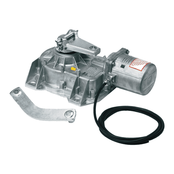
ATTENZIONE! importanti istruzioni per la sicurezza delle persone: LEGGERE ATTENTAMENTE! REMESSA UN PANNO LEGGERMENTE INUMIDITO CON ACQUA NON UTILIZZARE SOLVENTI O ALTRI PRODOTTI • I ’ ) • L PRODOTTO DEVE ESSERE DESTINATO SOLO ALL USO PER IL QUALE È STATO ESPRESSAMENTE CHIMICI CHE POTREBBERO ROVINARE I DISPOSITIVI NEL CASO SI RENDANO NECESSARIE .A. - Page 3 DESCRIZIONE FROG-A Motoriduttore irreversibile per cancelli a battente fi no a 3,5 m per anta, con fermo anta in chiusura regolabile. FROG-AE Motoriduttore irreversibile con encoder per cancelli a battente fi no a 3,5 m per anta, con fermo anta in chiusura regolabile.
-
Page 4: Impianto Tipo
Descrizione delle parti 1. Motoriduttore 2. Leva di trasmissione 3. Braccio motoriduttore 4. Vite di regolazione del finecorsa in chiusura 5. Leva di aggancio sblocco 6. Staffa di fissaggio al cancello 7. Vite di regolazione del finecorsa in apertura 8. Cassa di fondazione 9. - Page 5 Dimensioni INDICAZIONI GENERALI PER L'INSTALLAZIONE ⚠ L’installazione deve essere effettuata da personale qualificato ed esperto e nel pieno rispetto delle normative vigenti. Verifiche preliminari ⚠ Prima di procedere all’installazione dell’automazione è necessario: • Prevedere adeguato dispositivo di disconnessione onnipolare, con distanza maggiore di 3 mm tra i contatti, a sezionamento dell’alimentazione; •...
- Page 6 INSTALLAZIONE ⚠ Le seguenti illustrazioni sono solo esempi, in quanto lo spazio per il fissaggio dell’automazione e degli accessori varia a seconda degli ingombri. Spetta quindi all’installatore scegliere la soluzione più adatta. Le figure che seguono si riferiscono a una installazione standard con cassa di fondazione e motoriduttore a destra di un cancello con apertura verso l’interno.
- Page 7 Lubrificare il perno della cassa di fondazione, la leva di aggancio e il perno della staffa del cancello. Montare l’anta del cancello inserendo il cardine superiore. Verificare che l’anta si apra e si chiuda senza difficoltà. Fissare o saldare accuratamente l’anta alla staffa di fissaggio al cancello Fissaggio dello sblocco È...
-
Page 8: Fissaggio Del Motoriduttore
Fissaggio del motoriduttore Prima di fissare i motoriduttori, inserire le viti di regolazione nei bracci dei motoriduttori come da disegno. SINISTRO DESTRO Aprire l’anta per facilitare il posizionamento del motoriduttore nella cassa di fondazione e il suo fissaggio. Usare perni filettati e dadi (forniti). Dado M12 UNI 5588 Ø... - Page 9 Determinazione dei punti di finecorsa In apertura: - aprire completamente le ante (l’apertura massima è di 110°); - svitare la vite di regolazione fino al contatto con la cassa ; - stringere il dado per bloccare la posizione della vite. In chiusura: - chiudere completamente le ante;...
- Page 10 Collegamenti al quadro comando ⚠ Prima di intervenire sul quadro comando, togliere la tensione di linea. Motoriduttore Quadro comando FROG-A / FROG-AV ZA3N - ZM3E FROG-AE ZM3E COLLEGAMENTO MOTORIDUTTORI CON ENCODER (FROG-AE) M1 - Motoriduttore 230 V AC ritardato in apertura.
- Page 11 COLLEGAMENTO MOTORIDUTTORI SENZA ENCODER (FROG-A / FROG-AV) M1 - Motoriduttore 230 V AC ritardato in apertura. M2 - Motoriduttore 230 V AC ritardato in chiusura. Scatole di derivazione IP67 (non fornite) Marrone (*) Marrone (*) Nero (*) Nero (*) Giallo / Verde...
- Page 12 SBLOCCO MANUALE DELL’ANTA ⚠ L’operazione deve essere eff ettuata in assenza di tensione. ⚠ Lo sblocco manuale può causare un movimento incontrollato del cancello, se questo presenta problemi meccanici o se non è bilanciato. SBLOCCO Per sbloccare l’anta, inserire la chiave nella serratura dello sblocco e girarla in senso orario. Aprire l’anta fi no alla battuta di arresto. BLOCCO Per ribloccare, riportare l’anta in posizione di chiusura.
- Page 13 RISOLUZIONE DEI PROBLEMI PROBLEMI POSSIBILI CAUSE SOLUZIONI Il cancello non • Manca l’alimentazione • Verificare la presenza di rete si apre e non si • Il motoriduttore è sbloccato • Bloccare il motoriduttore chiude • Il trasmettitore ha la batteria scarica •...
- Page 14 Manutenzione straordinaria ⚠ La seguente tabella serve per registrare gli interventi di manutenzione straordinaria, di riparazione e di miglioramento eseguiti da ditte esterne specializzate. Gli interventi di manutenzione straordinaria devono essere effettuati da tecnici specializzati. Registro manutenzione straordinaria Timbro installatore Nome operatore Data intervento Firma tecnico...
- Page 15 DISMISSIONE E SMALTIMENTO ☞ CAME S.p.A. implementa all’interno dei propri stabilimenti un Sistema di Gestione Ambientale certificato e conforme alla norma UNI EN ISO 14001 a garanzia del rispetto e della tutela dell’ambiente. Vi chiediamo di continuare l’opera di tutela dell’ambiente, che CAME considera uno dei fondamenti di sviluppo delle proprie strategie operative e di mercato, semplicemente osservando brevi indicazioni in materia di smaltimento: SMALTIMENTO DELL’IMBALLO...
- Page 16 Came S.p.A. Came S.p.A. Via Martiri Della Libertà, 15 Via Cornia, 1/b - 1/c 31030 Dosson di Casier Dosson di Casier 33079 Sesto al Reghena Sesto al Reghena Treviso Treviso - Italy Pordenone Pordenone - Italy (+39) 0422 4940 (+39) 0434 698111...
- Page 17 UNDERGROUND OPERATOR FOR SWING GATES FA 01182 -EN INSTALLATION MANUAL FROG-A / FROG-AV / FROG-AE English...
-
Page 18: Read Carefully
WARNING! important safety instructions: READ CAREFULLY! • REMISE PREVENT POTENTIALLY HAZARDOUS SITUATIONS EAD THE INSTRUCTIONS IF THE POWER • E MPLOY THIS PRODUCT ONLY FOR THE USE FOR WHICH IT WAS EXPRESSLY MADE SUPPLY CABLE IS DAMAGED IT MUST BE REPLACED BY THE MANUFACTURER OR AUTHORIZED .A. -
Page 19: Intended Use
ARE IN MILLIMETERS DESCRIPTION FROG-A Irreversible gearmotor for swing gates with 3.5 m long leaves, with adjustable closing-leaf stop. FROG-AE Irreversible gearmotor - with encoder - for swing gates with 3.5 m long leaves, with adjustable closing-leaf stop. FROG-AV Irreversible gearmotor for swing gates with 1.3 m long leaves, with adjustable closing-leaf stop. - Page 20 Description of the components 1. Gearmotor 2. Transmission lever 3. Gearmotor arm 4. Limit switch adjusting screw when closing 5. Couple release lever 6. Mounting bracket to gate 7. Limit switch adjusting screw when closing 8. Foundation box 9. Casing hole 10.
-
Page 21: General Installation Instructions
Dimensions GENERAL INSTALLATION INSTRUCTIONS ⚠ Installation must be carried out by qualified and experienced personnel in compliance with applicable regulations. Preliminary checks ⚠ Before installing the operator: • Provide a suitable single-pole disconnection device, with a maximum of 3 mm between the contacts, to disconnect the power supply; •... - Page 22 INSTALLATION ⚠ The following illustrations are only examples, given that the space for securing the operator and accessories varies depending on the overall dimensions. The installation technician is responsible for choosing the most suitable solution. The following drawings refer to a standard installation of an inward opening gate. Laying the corrugated pipes and inspection chambers Make the hole for the box.
- Page 23 Lubricate the foundation case pin, the latch and the gate bracket pin. Install the gate leaf, inserting the upper hinge. Check that the leaf opens and closes without difficulty. Carefully fix or weld the door to the gate fixing bracket. Securing the release It is important to lubricate the release tab;...
- Page 24 Fastening the gearmotor Before fastening the gearmotors, fit the adjusting screws into the gearmotor drive arms, as shown in the drawing. LEFT RIGHT Open the leaf to simplify gearmotor installation and securing inside the foundation case. Use studs and nuts (supplied). Ø...
- Page 25 Determining the end run points During opening: - open the leaves completely (the maximum aperture is 110 °); - loosen the screw until it makes contact with the case - tighten the nut to lock the screw into position. During closing: - close the leaves completely;...
-
Page 26: Electrical Connections
Electrical connections ⚠ For electrical connection operations follow the information in the control panel technical documents. Gearmotor Control panel FROG-A / FROG-AV ZA3N - ZM3E FROG-AE ZM3E CONNECTING THE ENCODER-FITTED GEARMOTORS (FROG-AE) TO THE CONTROL PANEL M1 - 230 V AC delayed-opening gearmotor. -
Page 27: Final Operations
CONNECTING THE GEARMOTORS (FROG-A / FROG-AV) TO THE CONTROL PANEL M1 - 230 V AC delayed-opening gearmotor. M2- 230 V AC delayed-closing gearmotor. IP67 junction boxes (not supplied) Blue Blue Brown (*) Brown (*) Black (*) Black (*) Yellow / Green... - Page 28 LEAF MANUAL RELEASE ⚠ Manually releasing the gate may cause an uncontrolled movement of the gate due to possible mechanical anomalies or unbalancing. RELEASING Insert the key/lever into the release lock and turn it counter-clockwise. Open the leaf until reaching end run. LOCKING To relock the door, return it to its closed position.
-
Page 29: Troubleshooting
TROUBLESHOOTING MALFUNCTIONS POSSIBLE CAUSES CHECKS AND REMEDIES The gate does not open or • No power supply • Check for mains power close • The gearmotor is unlocked • Lock the gearmotor • The transmitter battery is flat • Replace the batteries •... - Page 30 Extraordinary maintenance ⚠ The table below is used to note any extraordinary maintenance, repairs or improvements carried out by specialist companies. ⚠ Extraordinary maintenance must be carried out by specialist technicians. Extraordinary maintenance log Installation technician stamp Operator name Date of intervention Technician signature Customer signature Intervention carried out _________________________________________________________________________________...
- Page 31 ☞ CAME S.p.A. implements an EN ISO 14001-certified and compliant Environmental Management System at its plants, to ensure environmental protection. Please continue our efforts to protect the environment, something that CAME considers to be one of the foundations in developing its business and market...
- Page 32 Came S.p.A. Came S.p.A. Via Martiri Della Libertà, 15 Via Cornia, 1/b - 1/c 31030 Dosson di Casier Dosson di Casier 33079 Sesto al Reghena Sesto al Reghena Treviso Treviso - Italy Pordenone Pordenone - Italy (+39) 0422 4940 (+39) 0434 698111...
-
Page 33: Manuel D'installation
AUTOMATISME ENTERRÉ POUR PORTAILS BATTANTS FA 01182 -F R MANUEL D’INSTALLATION FROG-A / FROG-AV / FROG-AE Français... - Page 34 OUTE AUTRE UTILISATION EST À CONSIDÉRER COMME DANGEREUSE PHOTOCELLULES Y PASSER DEVANT UN OBJET DURANT LA FERMETURE SI L AUTOMATISME .A. D A SOCIÉTÉ CAME ÉCLINE TOUTE RESPONSABILITÉ EN CAS D ÉVENTUELS DOMMAGES INVERSE LE SENS DE LA MARCHE OU QU IL SE BLOQUE LES PHOTOCELLULES FONCTIONNENT •...
- Page 35 LES DIMENSIONS SONT EXPRIMÉES EN MILLIMÈTRES, SAUF INDICATION CONTRAIRE. DESCRIPTION FROG-A Motoréducteur irréversible pour portails battants jusqu’à 3,5 m par vantail, avec butée réglable du vantail en fermeture. FROG-AE Motoréducteur irréversible avec encodeur pour portails battants jusqu’à 3,5 m par vantail, avec butée réglable du vantail en fermeture.
-
Page 36: Installation Type
Description des parties 1. Motoréducteur 2. Levier de transmission 3. Bras motoréducteur 4. Vis de réglage du fin de course en phase de fermeture 5. Levier de fixation du dispositif de déblocage 6. Étrier de fixation au portail 7. Vis de réglage du fin de course en phase d'ouverture 8. - Page 37 Dimensions INSTRUCTIONS GÉNÉRALES POUR L'INSTALLATION ⚠ L’installation doit être effectuée par du personnel qualifié et dans le plein respect des normes en vigueur. Contrôles préliminaires ⚠ Avant d'installer l'automatisme, il faut : • Prévoir un dispositif de déconnexion omnipolaire spécifique, avec un espace de plus de 3 mm entre les contacts, pour le sectionnement de l'alimentation. •...
- Page 38 INSTALLATION ⚠ Les illustrations suivantes ne sont que des exemples étant donné que l'espace pour la fixation de l'automatisme et des accessoires varie en fonction des encombrements. C'est donc l'installateur qui doit choisir la solution la plus indiquée. Les figures suivantes se réfèrent à l’installation standard d’un portail s’ouvrant vers l’intérieur. Pose des tuyaux ondulés et des boîtiers de dérivation Creuser la fosse pour la caisse.
- Page 39 Lubrifier le pivot de la caisse de fondation, le levier de fixation et le goujon de l'étrier du portail. Monter le vantail du portail sur la charnière supérieure. S'assurer que le vantail s'ouvre et se ferme facilement. Fixer ou souder soigneusement le vantail sur l'étrier de fixation au portail. Fixation du dispositif de déblocage Il est important de bien graisser la languette de fixation du dispositif de déblocage ;...
-
Page 40: Fixation Du Motoréducteur
Fixation du motoréducteur Introduire les vis de réglage dans les bras des motoréducteurs comme indiqué sur le dessin avant de fixer ces derniers. GAUCHE DROIT Ouvrir le vantail pour faciliter le positionnement du motoréducteur dans la caisse de fondation ainsi que sa fixation. Utiliser les goujons filetés et les écrous fournis. - Page 41 Détermination des points de fin de course En phase d'ouverture : - ouvrir complètement les vantaux (l’ouverture maximale est de 110°) ; - dévisser la vis de réglage jusqu'au contact avec la caisse - serrer l'écrou pour bloquer la position de la vis. En phase de fermeture : - fermer complètement les vantaux ;...
-
Page 42: Branchements Électriques
Branchements électriques ⚠ Pour les opérations de branchement électrique, se référer à la documentation technique de l'armoire. Motoréducteur Armoire de commande FROG-A / FROG-AV ZA3N - ZM3E FROG-AE ZM3E CONNEXION À L’ARMOIRE DE COMMANDE DES MOTORÉDUCTEURS AVEC ENCODEUR (FROG-AE) M2 - Motoréducteur 230 VAC retardé à la fermeture. - Page 43 CONNEXION À L’ARMOIRE DE COMMANDE DES MOTORÉDUCTEURS (FROG-A / FROG-AV) M2 - Motoréducteur 230 VAC retardé à la fermeture. M1 - Motoréducteur 230 VAC retardé à l’ouverture. Boîtiers de dérivation IP67 (non fournis) Bleu Bleu Marron (*) Marron (*) Noir (*)
- Page 44 DÉBLOCAGE MANUEL DU MOTORÉDUCTEUR ⚠ L’activation du débrayage manuel peut provoquer un mouvement incontrôlé du portail à cause d’anomalies mécaniques ou d’un déséquilibrage. DÉBRAYAGE Introduire la clé/levier dans la serrure du dispositif de déblocage et la tourner dans le sens anti-horaire. Ouvrir le vantail jusqu’à la butée d’arrêt. EMBRAYAGE Pour bloquer à...
-
Page 45: Résolution Des Problèmes
RÉSOLUTION DES PROBLÈMES DÉFAUTS DE FONCTIONNE- CAUSES POSSIBLES CONTRÔLES ET REMÈDES MENT Le portail ne s'ouvre pas et ne • Défaut d'alimentation • Contrôler l'alimentation secteur se ferme pas • Le motoréducteur est débloqué • Bloquer le motoréducteur • La batterie de l'émetteur est déchargée •... - Page 46 Entretien curatif ⚠ Le tableau suivant permet d'enregistrer les interventions d'entretien curatif, de réparation et d'amélioration effectuées par des sociétés externes spécialisées. ⚠ Les interventions d'entretien curatif doivent être effectuées par des techniciens qualifiés. Registre entretien curatif Timbre installateur Nom opérateur Date intervention Signature technicien Signature client...
- Page 47 MISE AU REBUT ET ÉLIMINATION ☞ CAME S.p.A. adopte dans ses établissements un Système de Gestion Environnementale certifié et conforme à la norme UNI EN ISO 14001 qui garantit le respect et la sauvegarde de l'environnement. Nous vous demandons de poursuivre ces efforts de sauvegarde de l'environnement, que CAME considère comme l'un des fondements du développement de ses propres stratégies opérationnelles et de marché, en observant tout simplement de brèves indications en matière d'élimination :...
- Page 48 Came S.p.A. Came S.p.A. Via Martiri Della Libertà, 15 Via Cornia, 1/b - 1/c 31030 Dosson di Casier Dosson di Casier 33079 Sesto al Reghena Sesto al Reghena Treviso Treviso - Italy Pordenone Pordenone - Italy (+39) 0422 4940 (+39) 0434 698111...
-
Page 49: Инструкция По Монтажу
АВТОМАТИКА ПОДЗЕМНОЙ УСТАНОВКИ ДЛЯ РАСПАШНЫХ ВОРОТ FA01 182 -RU ИНСТРУКЦИЯ ПО МОНТАЖУ FROG-A / FROG-AV / FROG-AE Русский... - Page 50 ВНИМАНИЕ! Важные правила техники безопасности: ПРОЧИТАЙТЕ ВНИМАТЕЛЬНО! П РЕДИСЛОВИЕ ФУНКЦИОНАЛЬНУЮ ПРОВЕРКУ РАБОТЫ ФОТОЭЛЕМЕНТОВ И ЧУВСТВИТЕЛЬНЫХ ПРОФИЛЕЙ • Д . Ч АННОЕ ИЗДЕЛИЕ ДОЛЖНО ИСПОЛЬЗОВАТЬСЯ ИСКЛЮЧИТЕЛЬНО ПО НАЗНАЧЕНИЮ КАЖДЫЕ ШЕСТЬ МЕСЯЦЕВ ТОБЫ ПРОВЕРИТЬ ИСПРАВНОСТЬ ФОТОЭЛЕМЕНТОВ ПРОВЕДИТЕ Л .A. С . Е ЮБОЕ...
-
Page 51: Условные Обозначения
ЕСЛИ НЕ УКАЗАНО ИНОЕ ОПИСАНИЕ FROG-A Нереверсивный редукторный двигатель для распашных ворот со створкой шириной до 3,5 м с регулируемым упором при закрывании. FROG-AE Нереверсивный редукторный двигатель с энкодером для распашных ворот со створкой шириной до 3,5 м с регулируемым упором при... -
Page 52: Основные Компоненты
Основные компоненты 1. Привод 2. Рычаг передачи 3. Рычаг редуктора 4. Регулировочный болт крайнего положения при закрывании 5. Нижний рычаг с креплением механизма для разблокировки 6. Верхний рычаг, монтируемый к створке 7. Регулировочный болт крайнего положения при открывании 8. Монтажный корпус 9. -
Page 53: Предварительные Проверки
Габаритные размеры ОБЩИЕ ИНСТРУКЦИИ ПО МОНТАЖУ ⚠ Монтаж должен производиться квалифицированным персоналом в полном соответствии с требованиями действующих норм безопасности. Предварительные проверки ⚠ Перед началом монтажных работ выполните следующее: • Убедитесь в том, что питание блока управления осуществляется от отдельной линии с соответствующим автоматическим выключателем с расстоянием... - Page 54 МОНТАЖ ⚠ Приведенные ниже рисунки носят иллюстративный характер, так как пространство для установки автоматики и дополнительных принадлежностей может меняться от случая к случаю. Таким образом, выбор наиболее подходящего решения должен осуществляться монтажником на месте. На расположенных ниже рисунках изображен стандартный монтаж распашных ворот с открыванием вовнутрь. Установка...
- Page 55 Смажьте осевой стержень монтажного корпуса и трущиеся части нижнего и верхнего рычагов. Установите створку сверху на петлю ворот, а снизу на верхний рычаг. Проверьте, чтобы створка свободно открывалась и закрывалась. Прикрепите или приварите верхний рычаг к створке ворот. Установка устройства разблокировки Важно...
- Page 56 Крепление привода Перед установкой редукторных двигателей вставьте регулировочные винты в рычаги редукторного двигателя, как показано на чертеже. СЛЕВА СПРАВА Откройте створку, чтобы упростить размещение привода в монтажном корпусе и его крепление. Используйте шпильки с резьбой и гайки (поставляются в комплекте). Ø...
- Page 57 Установка крайних положений При открывании: - откройте створки ворот до упора (максимальный угол открывания — 110°); - отверните регулировочный болт до соприкосновения с монтажным корпусом - затяните гайку , чтобы блокировать положение болта. При закрывании: - полностью закройте створки; ...
-
Page 58: Электрические Подключения
ЭЛЕКТРИЧЕСКИЕ ПОДКЛЮЧЕНИЯ ⚠ При выполнении электрических подключений руководствуйтесь указаниями в технической документации на блок управления. Привод Блок управления FROG-A / FROG-AV ZA3N - ZM3E FROG-AE ZM3E ПОДКЛЮЧЕНИЕ ПРИВОДОВ С ЭНКОДЕРОМ К БЛОКУ УПРАВЛЕНИЯ (FROG-AE) M1 - Привод ~230 В, с задержкой при открывании. -
Page 59: Заключительные Работы
ПОДКЛЮЧЕНИЕ ПРИВОДОВ К БЛОКУ УПРАВЛЕНИЯ (FROG-A / FROG-AV) M1 - Привод ~230 В, с задержкой при открывании. M2 - Привод ~230 В, с задержкой при закрывании. Распределительные коробки IP67 (не входят в комплект поставки) Blue Blue Brown (*) Brown (*) - Page 60 РУЧНАЯ РАЗБЛОКИРОВКА ПРИВОДА ⚠ Активация ручной разблокировки может привести к неконтролируемому движению автоматики, вызванному ме-ханическими неисправностями или нарушением балансировки. РАЗБЛОКИРОВКА Вставьте ключ/рычаг в замок разблокировки и поверните его против часовой стрелки. Откройте створку до механического упора открывания. БЛОКИРОВКА Блокировка: Для блокировки створки установите ее в исходное положение. МОНТАЖ...
-
Page 61: Устранение Неисправностей
УСТРАНЕНИЕ НЕИСПРАВНОСТЕЙ НЕИСПРАВНОСТЬ ВОЗМОЖНАЯ ПРИЧИНА СПОСОБ УСТРАНЕНИЯ Ворота не открываются и не • Отключено электропитание. • Включите электропитание. закрываются. • Разблокирован привод. • Заблокируйте привод. • Разрядились батарейки брелока-передатчика. • Замените батарейки. • Сломан брелок-передатчик. • Обратитесь к установщику. • Кнопка "Стоп" заедает или сломана. •... - Page 62 Внеплановое техническое обслуживание ⚠ Эта таблица необходима для записи внеплановых работ по обслуживанию и ремонту оборудования, выполненных специализированными предприятиями. ⚠ Ремонт оборудования должен осуществляться квалифицированными специалистами. Бланк регистрации работ по внеплановому техническому обслуживанию Место печати Компания Дата проведения работ Подпись установщика Подпись...
-
Page 63: Утилизация Упаковки
УТИЛИЗАЦИЯ ☞ CAME S.p.A. имеет сертификат системы защиты окружающей среды UNI EN ISO 14001, гарантирующий экологическую безопасность на ее заводах. Мы просим, чтобы вы продолжали защищать окружающую среду. САМЕ считает одним из фундаментальных пунктов стратегии рыночных отношений выполнение этих кратких руководящих принципов: УТИЛИЗАЦИЯ... - Page 64 Came S.p.A. Came S.p.A. Via Martiri Della Libertà, 15 Via Cornia, 1/b - 1/c 31030 Dosson di Casier Dosson di Casier 33079 Sesto al Reghena Sesto al Reghena Treviso Treviso - Italy Pordenone Pordenone - Italy (+39) 0422 4940 (+39) 0434 698111...
Need help?
Do you have a question about the FROG-A and is the answer not in the manual?
Questions and answers