
Subscribe to Our Youtube Channel
Related Manuals for CAME FA70230


Summary of Contents for CAME FA70230
- Page 1 AUTOMAZIONE PER CANCELLI A BATTENTE FA0 0123 M 0 4 Italiano English MANUALE DI INSTALLAZIONE Français FA70230E Русский...
- Page 2 SENSIBILI OGNI SEI MESI ER CONTROLLARE CHE LE FOTOCELLULE FUNZIONINO ESPRESSAMENTE STUDIATO GNI ALTRO USO È DA CONSIDERARSI PERICOLOSO ’ CAME S. PASSARE UN OGGETTO DAVANTI DURANTE LA CHIUSURA SE L AUTOMAZIONE INVERTE NON È RESPONSABILE PER EVENTUALI DANNI CAUSATI DA USI IMPROPRI •...
- Page 3 LEGENDA Questo simbolo indica parti da leggere con attenzione. ⚠ Questo simbolo indica parti riguardanti la sicurezza. ☞ Questo simbolo indica cosa comunicare all’utente. DESCRIZIONE Motoriduttore irreversibile con encoder per cancelli a battente fi no a 2,3 m per anta. Destinazione d'uso Il motoriduttore è...
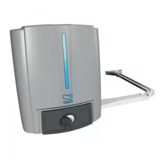
- Page 4 Descrizione delle parti 1. Coperchio 2. Staff a pilastro 3. Spessore in gomma 4. Motoriduttore 5. Morsetto di alimentazione 6. Sportello di sblocco 7. Braccio di trasmissione 8. Braccio condotto 9. Staff a cancello 10. Fermi meccanici Impianto tipo 1. Automazione 2.
- Page 5 Esempi di applicazione Applicazione con braccio di trasmissione snodato (standard). Applicazione con braccio di trasmissione dritto e guida di scorrimento (STYLO-BD). INDICAZIONI GENERALI PER L'INSTALLAZIONE ⚠ L’installazione deve essere effettuata da personale qualificato ed esperto e nel pieno rispetto delle normative vigenti. Verifiche preliminari ⚠ ...
-
Page 6: Installazione
INSTALLAZIONE ⚠ Le seguenti illustrazioni sono solo esempi, in quanto lo spazio per il fissaggio del motoriduttore e degli accessori varia a seconda degli ingombri. Spetta all’installatore scegliere la soluzione più adatta. I disegni si riferiscono all’automazione installata a sinistra. L’installazione del motoriduttore a destra è simmetrica. Posa dei tubi corrugati Predisporre i tubi corrugati necessari per i collegamenti provenienti dal pozzetto di derivazione. - Page 7 Segnare i punti di fissaggio della staffa pilastro e della staffa cancello. Le misure di interasse dei fori delle staffe sono indicate nel paragrafo dimensioni. Forare i punti di fissaggio, inserire i tasselli o utilizzare degli inserti adeguati per la tenuta delle staffe. ...
- Page 8 Fissaggio dell’automazione Inserire il motoriduttore nella staffa pilastro e fissarlo con le viti e i dadi. Inserire la spina nel foro dell’albero motoriduttore. Fissare il braccio di trasmissione all’albero con la rondella per albero lento e la vite. UNI 6593 UNI 5739 Ø...
- Page 9 Sbloccare il motoriduttore (vedi SBLOCCO DEL MOTORIDUTTORE), fissare il braccio condotto alla staffa cancello come indicato nel disegno. Ø 12 UNI 6592 Ø 12 UNI 6593 UNI 5739 Ø 6 M6x10 ⚠ ATTENZIONE! Se non ci sono le battute d’arresto, è obbligatorio fissare i fermi meccanici. Fissaggio dei fermi meccanici Sbloccare il motoriduttore.
- Page 10 Determinazione dei punti di finecorsa Con il motoriduttore sbloccato e con l’anta chiusa, regolare il grano del finecorsa di chiusura girandolo in senso orario o antiorario (). Fissare il grano con il dado (). Allo stesso modo, regolare il finecorsa di apertura sul grano dell’altro fermo ().
-
Page 11: Collegamenti Elettrici
COLLEGAMENTI ELETTRICI ⚠ Attenzione! Prima di intervenire sul quadro comando, togliere la tensione di linea e, se presenti, scollegare le batterie. Motoriduttore 230 V AC installato a destra Motoriduttore 230 V AC installato a sinistra (vista interna), ritardato in chiusura. (vista interna), ritardato in apertura. - Page 12 OPERAZIONI FINALI Le operazioni fi nali sono da eff ettuare a collegamenti terminati e messa in funzione. SBLOCCO DEL MOTORIDUTTORE ⚠ L’operazione deve essere eff ettuata in assenza di tensione. ⚠ Lo sblocco manuale dell’automazione può causare un movimento incontrollato del cancello, se questo presenta problemi meccanici o se non è...
- Page 13 INSTALLAZIONE E COLLEGAMENTI PER APERTURA VERSO L’ESTERNO Di seguito, le uniche operazioni che variano rispetto all’installazione standard: Fissaggio delle staffe Determinare il punto di fissaggio della staffa cancello e ricavare il punto di fissaggio della staffa pilastro, rispettando le quote riportate nel disegno e nella tabella.
- Page 14 Fissaggio dei fermi meccanici Sbloccare il motoriduttore. In apertura. Aprire completamente l’anta. Fare un segno sulla cassa in corrispondenza del centro del braccio (). Chiudere manualmente l’anta. Posizionare il fermo meccanico sotto la cassa. Il segno sulla cassa deve corrispondere alla scanalatura sul fermo come illustrato (). Fissare il fermo con la vite ().
- Page 15 Collegamenti elettrici ⚠ Attenzione! Prima di intervenire sul quadro comando, togliere la tensione di linea e, se presenti, scollegare le batterie. Motoriduttore 230 V AC installato a destra Motoriduttore 230 V AC installato a sinistra (vista interna), ritardato in chiusura. (vista interna), ritardato in apertura.
-
Page 16: Risoluzione Dei Problemi
RISOLUZIONE DEI PROBLEMI PROBLEMI POSSIBILI CAUSE SOLUZIONI Il cancello non • Manca l’alimentazione • Verificare la presenza di alimentazione si apre e non si • Il motoriduttore è sbloccato • Bloccare il motoriduttore chiude • Il trasmettitore ha la batteria scarica •... - Page 17 Manutenzione straordinaria ⚠ La seguente tabella serve per registrare gli interventi di manutenzione straordinaria, di riparazione e di miglioramento eseguiti da ditte esterne specializzate. Gli interventi di manutenzione straordinaria devono essere effettuati da tecnici specializzati. Registro manutenzione straordinaria Timbro installatore Nome operatore Data intervento Firma tecnico...
-
Page 18: Riferimenti Normativi
DISMISSIONE E SMALTIMENTO ☞ CAME S.p.A. implementa all’interno dei propri stabilimenti un Sistema di Gestione Ambientale certificato e conforme alla norma UNI EN ISO 14001 a garanzia del rispetto e della tutela dell’ambiente. Vi chiediamo di continuare l’opera di tutela dell’ambiente, che CAME considera uno dei fondamenti di sviluppo delle proprie strategie operative e di mercato, semplicemente osservando brevi indicazioni in materia di smaltimento: SMALTIMENTO DELL’IMBALLO... - Page 20 Came S.p.A. Came S.p.A. Via Martiri Della Libertà, 15 Via Cornia, 1/b - 1/c 31030 Dosson di Casier Dosson di Casier 33079 Sesto al Reghena Sesto al Reghena Treviso Treviso - Italy Pordenone Pordenone - Italy (+39) 0422 4940 (+39) 0434 698111...
- Page 21 SWING-GATE OPERATOR FA 00123 -E N INSTALLATION MANUAL FA70230E English...
- Page 22 POWER ON ONSTANTLY CLEAN THE PHOTOCELLS GLASS COVERS USING A SLIGHTLY SE THIS PRODUCT ONLY FOR ITS EXPLICITELY INTENDED PURPOSE NY OTHER . CAME S. WATER MOISTENED CLOTH DO NOT USE SOLVENTS OR OTHER CHEMICAL PRODUCTS USE IS DANGEROUS IS NOT LIABLE FOR ANY DAMAGE CAUSED BY •...
-
Page 23: Intended Use
LEGEND This symbol shows which parts to read carefully. ⚠ This symbol shows which parts describe safety issues. ☞ This symbol shows which parts to tell users about. DESCRIPTION Encoder-fi tted irreversible gearmotor for swing gates with leaves of up to 2.3 m each. Intended use This gearmotor is designed to power and operate swing gates in private homes and apartment blocks. - Page 24 Description of parts 1. Cover 2. Post brace 3. Rubber shim 4. Gearmotor 5. Power supply terminal 6. Release hatch 7. Transmission arm 8. Joint arm 9. Gate brace 10. Mechanical stops Standard installation 1. Operator 2. Gearmotor 3. Flashing light 4.
- Page 25 Applicative examples Fitted with standard jointed transmission-arm. Fitted with the STYLO-BD straight transmission-arm and slide rail. GENERAL INSTALLATION INDICATIONS ⚠ Only skilled, qualified staff must install this product. Preliminary checks ⚠ Before beginning, do the following: • check that the gate structure is sturdy enough, the hinges work efficiently and that there is no friction between the fixed and moving parts; •...
-
Page 26: Installation
INSTALLATION ⚠ The following illustrations are just examples, in that the space available for fitting the operator and accessories varies depending on the overall dimensions. It is up to the installer to find the most suitable solution. The drawing show an operator fitted on the left. Install the operator on the right, symmetrically. Corrugate tube laying Lay the corrugated tubes you will need for the cables coming out of the junction pit. - Page 27 Mark the spots where the gate-post brace and gate brace will be fitted. The center-distances of the holes on the braces are shown in the Dimensions paragraph. Drill the anchoring points, fit the dowels or use plugs that will hold fast the screws. ...
-
Page 28: Fastening The Operator
Fastening the operator Fit the gearmotor into the gate.post brace and tighten the nuts and bolts. Fit the plug into the gearmotor's drive-shaft hole. Fasten the transmission arm to the drive-shaft using the slow-shaft washer and bolt. UNI 6593 UNI 5739 Ø... - Page 29 Release the gearmotor (see RELEASING THE GEARMOTOR), fit the driven arm to the gate brace as shown in the drawing. Ø 12 UNI 6592 Ø 12 UNI 6593 UNI 5739 Ø 6 M6x10 ⚠ WARNING! If no gate-leaf stops are in place, you must fit the mechanical stops. Fastening the mechanical stops Release the gearmotor.
- Page 30 Establishing the limit-switch points With the gearmotor released and the gate-leaf closed, adjust the closing limit- switch grub screw by turning it clockwise or counterclockwise (). Tighten the nut to fasten the grub-screw (). In the same way, set the opening limit-switch on the other stop's grub screw ().
-
Page 31: Electrical Connections
ELECTRICAL CONNECTIONS ⚠ Warning! Before working on the control panel, cut off the mains current supply and, if present, remove any batteries. 230 V AC gearmotor fi tted on the right (inside 230 V AC gearmotor fi tted on the left (inside view), with delayed closing. -
Page 32: Final Operations
FINAL OPERATIONS Perform the fi nal operations once all connections are complete and the system is up and running. RELEASING THE GEARMOTOR ⚠ This procedure must be done with the main power cut off . ⚠ Manually releasing the operator may result in uncontrolled movement of the gate, if this has any mechanical problems or is unbalanced. RELEASE LOCK... -
Page 33: Fastening The Brackets
INSTALLING AND CONNECTIONS FOR OUTER OPENING Following, are the only things that change compared to a standard installation: Fastening the brackets Establish where you will fit the gate brace and measure where the gate-post brace will fit. Make sure to respect the quotas shown in the drawing and table. -
Page 34: Fastening The Mechanical Stops
Fastening the mechanical stops Release the gearmotor. When opening. Entirely open the gate leaf. Mark the casing where the center of the arm is.(). Manually close the gate leaf. Place the mechanical stop under the casing. The mark on the case must match the groove on the stop, as shown(). - Page 35 Electrical connections ⚠ Warning! Before working on the control panel, cut off the mains current supply and, if present, remove any batteries. 230 V AC gearmotor fi tted on the right (inside 230 V AC gearmotor fi tted on the left (inside view), with delayed closing.
-
Page 36: Troubleshooting
TROUBLESHOOTING TROUBLES POSSIBLE CAUSES FIXES It neither opens • Power supply missing • Check whether the power is on nor closes • The gearmotor is stuck • Lock the gearmotor • The transmitter's battery is run down • Replace the batteries •... - Page 37 Extraordinary maintenance ⚠ The following table is for logging any extraordinary maintenance jobs, repairs and improvements performed by specialized contractors. Any extraordinary maintenance jobs must be done only by specialized technicians. Extraordinary maintenance log Fitter's stamp Name of operator Job performed on (date) Technician's signature Requester's signature...
-
Page 38: Dismantling And Disposal
☞ CAME S.p.A. applies a certified UNI EN ISO 14001 standard-compliant Environmental Management System at its premises to ensure the environment is safeguarded. Please help us safeguard the environment. At CAME it is fundamental to our operating and market strategies. Simply follow these brief disposal guidelines:... - Page 40 Came S.p.A. Came S.p.A. Via Martiri Della Libertà, 15 Via Cornia, 1/b - 1/c 31030 Dosson di Casier Dosson di Casier 33079 Sesto al Reghena Sesto al Reghena Treviso Treviso - Italy Pordenone Pordenone - Italy (+39) 0422 4940 (+39) 0434 698111...
- Page 41 AUTOMATISME POUR PORTAILS BATTANTS FA00123 - FR MANUEL D'INSTALLATION FA70230E Français...
- Page 42 E PRODUIT NE DEVRA ÊTRE DESTINÉ QU À L UTILISATION POUR LAQUELLE IL A ET DISPOSITIFS DE FIXATION LES CÂBLES ET LES CONNEXIONS ACCESSIBLES ÉTÉ EXPRESSÉMENT CONÇU OUTE AUTRE UTILISATION EST À CONSIDÉRER COMME . CAME S. POINTS D ARTICULATION CHARNIÈRES ET DE FROTTEMENT GLISSIÈRES DOIVENT DANGEREUSE DÉCLINE TOUTE RESPONSABILITÉ...
- Page 43 LÉGENDE Ce symbole indique des parties à lire attentivement. ⚠ Ce symbole indique des parties concernant la sécurité. ☞ Ce symbole indique ce qui doit être communiqué à l'utilisateur. DESCRIPTION Motoréducteur irréversible avec encodeur pour portails battants jusqu'à 2,3 m par vantail. Utilisation prévue Le motoréducteur a été...
- Page 44 Description des parties 1. Couvercle 2. Étrier pilier 3. Entretoise en caoutchouc 4. Motoréducteur 5. Borne d'alimentation 6. Volet de déblocage 7. Bras de transmission 8. Bras courbé 9. Étrier portail 10. Butées mécaniques Installation standard 1. Automatisme 2. Motoréducteur 3.
- Page 45 Exemples d'application Application avec bras de transmission articulé (standard). Application avec bras de transmission droit et rail de guidage (STYLO-BD). INSTRUCTIONS GÉNÉRALES POUR L'INSTALLATION ⚠ L’installation doit être effectuée par du personnel qualifié et dans le plein respect des normes en vigueur. Contrôles préliminaires ⚠ ...
- Page 46 INSTALLATION ⚠ Les illustrations suivantes ne sont que des exemples étant donné que l'espace pour la fixation du motoréducteur et des accessoires varie en fonction des encombrements. C'est donc l'installateur qui doit choisir la solution la plus indiquée. Les dessins illustrent l'automatisme installé à gauche. L’installation du motoréducteur à droite est symétrique. Pose des gaines annelées Prévoir les gaines annelées nécessaires pour les raccordements issus du boîtier de dérivation.
- Page 47 Noter les points de fixation de l'étrier pilier et de l'étrier portail. Les cotes d'entraxe des trous des étriers sont indiquées au paragraphe dimensions. Percer les points de fixation, introduire les chevilles ou utiliser des éléments adéquats pour la fixation des étriers. ...
- Page 48 Fixation de l'automatisme Introduire le motoréducteur dans l'étrier pilier et le fixer à l'aide des vis et des écrous. Introduire la cheville dans le trou de l'arbre du motoréducteur. Fixer le bras de transmission à l'arbre à l'aide de la rondelle pour arbre lent et de la vis. UNI 6593 UNI 5739 Ø...
- Page 49 Débloquer le motoréducteur (voir DÉBLOCAGE DU MOTORÉDUCTEUR), fixer le bras courbé à l'étrier de fixation au portail comme indiqué sur le dessin. Ø 12 UNI 6592 Ø 12 UNI 6593 UNI 5739 Ø 6 M6x10 ⚠ ATTENTION ! À défaut de butées d'arrêt, il est obligatoire de fixer les butées mécaniques. Fixation des butées mécaniques Débloquer le motoréducteur.
- Page 50 Détermination des points de fin de course Avec motoréducteur débloqué et vantail fermé, régler le goujon de la butée de fin de course de fermeture en le tournant dans le sens horaire ou anti-horaire (). Fixer le goujon à l'aide de l'écrou (). Régler de la même manière la butée de fin de course d'ouverture en intervenant sur le goujon de l'autre butée ().
-
Page 51: Branchements Électriques
BRANCHEMENTS ÉLECTRIQUES ⚠ Attention ! Avant d'intervenir sur l'armoire de commande, mettre hors tension et déconnecter les éventuelles batteries. Motoréducteur 230 VAC installé à droite (vue Motoréducteur 230 VAC installé à gauche (vue interne), retardé à la fermeture. interne), retardé à l'ouverture. ZM3E ENCODEUR A ENCODEUR B... - Page 52 OPÉRATIONS FINALES Les opérations fi nales sont à eff ectuer au terme des connexions et après avoir contrôlé que tout fonctionne correctement, y compris le moteur. DÉBLOCAGE DU MOTORÉDUCTEUR ⚠ Mettre hors tension avant d'eff ectuer cette opération. ⚠ Le déblocage manuel de l'automatisme peut provoquer un mouvement incontrôlé du portail si ce dernier présente des problèmes mécaniques ou s'il n'est pas équilibré.
- Page 53 INSTALLATION ET CONNEXIONS POUR L'OUVERTURE VERS L'EXTÉRIEUR Les opérations décrites ci-après sont les seules qui varient par rapport à l’installation standard : Fixation des étriers Identifier le point de fixation de l'étrier portail et établir celui de l'étrier pilier en respectant les dimensions indiquées sur le dessin et dans le tableau. Dimensions application (mm) Ouverture vantail (°) C MAX.
- Page 54 Fixation des butées mécaniques Débloquer le motoréducteur. En phase d'ouverture. Ouvrir complètement le vantail. Tracer une ligne au crayon sur la caisse au niveau du centre du bras (). Fermer manuellement le vantail. Positionner la butée mécanique sous la caisse. Le signe sur la caisse doit correspondre à...
- Page 55 Branchements électriques ⚠ Attention ! Avant d'intervenir sur l'armoire de commande, mettre hors tension et déconnecter les éventuelles batteries. Motoréducteur 230 VAC installé à droite (vue Motoréducteur 230 VAC installé à gauche (vue interne), retardé à la fermeture. interne), retardé à l'ouverture. ZM3E ENCODEUR A ENCODEUR B...
-
Page 56: Résolution Des Problèmes
RÉSOLUTION DES PROBLÈMES PROBLÈMES CAUSES POSSIBLES SOLUTIONS Le portail ne • Défaut d'alimentation • S'assurer de la présence de l'alimentation s'ouvre pas et ne • Le motoréducteur est débloqué • Bloquer le motoréducteur se ferme pas • La pile de l'émetteur est déchargée •... - Page 57 Entretien curatif ⚠ Le tableau suivant permet d'enregistrer les interventions d'entretien curatif, de réparation et d'amélioration effectuées par des sociétés externes spécialisées. Les interventions d'entretien curatif doivent être effectuées par des techniciens qualifiés. Registre entretien curatif Cachet installateur Nom opérateur Date intervention Signature technicien Signature client...
- Page 58 MISE AU REBUT ET ÉLIMINATION ☞ CAME S.p.A. adopte dans ses établissements un Système de Gestion Environnementale certifié et conforme à la norme UNI EN ISO 14001 qui garantit le respect et la sauvegarde de l'environnement. Nous vous demandons de poursuivre ces efforts de sauvegarde de l'environnement, que CAME considère comme l'un des fondements du développement de ses propres stratégies opérationnelles et de marché, en observant tout simplement de brèves indications en matière...
- Page 60 Came S.p.A. Came S.p.A. Via Martiri Della Libertà, 15 Via Cornia, 1/b - 1/c 31030 Dosson di Casier Dosson di Casier 33079 Sesto al Reghena Sesto al Reghena Treviso Treviso - Italy Pordenone Pordenone - Italy (+39) 0422 4940 (+39) 0434 698111...
- Page 61 АВТОМАТИКА ДЛЯ РАСПАШНЫХ ВОРОТ FA00123-RU ИНСТРУКЦИЯ ПО МОНТАЖУ FA70230E Русский...
- Page 62 • Э . Л ПРОВОДКЕ И ДОСТУПНЫХ ПОДКЛЮЧЕНИЯХ ЛЕДИТЕ ЗА ЧИСТОТОЙ И СМАЗКОЙ ТО ИЗДЕЛИЕ ДОЛЖНО ИСПОЛЬЗОВАТЬСЯ ИСКЛЮЧИТЕЛЬНО ПО НАЗНАЧЕНИЮ ЮБОЕ ) • В . CAME S. МЕХАНИЗМОВ ДВИЖЕНИЯ ПЕТЕЛЬ И СКОЛЬЖЕНИЯ НАПРАВЛЯЮЩИХ ЫПОЛНЯЙТЕ ДРУГОЕ ПРИМЕНЕНИЕ РАССМАТРИВАЕТСЯ КАК ОПАСНОЕ СНИМАЕТ С...
-
Page 63: Условные Обозначения
УСЛОВНЫЕ ОБОЗНАЧЕНИЯ Этот символ обозначает раздел, требующий особого внимания. ⚠ Этот символ обозначает раздел, связанный с вопросами безопасности. ☞ Этот символ обозначает раздел, предназначенный для ознакомления конечного пользователя. ОПИСАНИЕ Самоблокирующийся привод с энкодером для створок шириной до 2,3 м. Назначение... - Page 64 Основные компоненты 1. Корпус 2. Монтажное основание 3. Резиновый уплотнитель 4. Мотор-редуктор 5. Контакты подключения 6. Дверца разблокировки 7. Рычаг прямой 8. Рычаг изогнутый 9. Скоба 10. Механические упоры Вариант типовой установки 1. Привод (левосторонняя установка) 2. Привод (правосторонняя установка) 3.
-
Page 65: Предварительные Проверки
Варианты типовой установки Вариант установки с шарнирным рычагом (стандартный). Вариант установки со скользящим рычагом и направляющей (STYLO-BD). ОБЩИЕ ИНСТРУКЦИИ ПО МОНТАЖУ ⚠ Монтаж должен производиться квалифицированным персоналом в полном соответствии с требованиями действующих норм безопасности. Предварительные проверки ⚠ Перед тем как приступить к монтажным работам, выполните следующее: •... - Page 66 МОНТАЖ ⚠ Приведенные ниже рисунки носят иллюстративный характер, так как пространство для крепления автоматики и дополнительных принадлежностей может меняться от случая к случаю. Выбор наиболее подходящего решения должен осуществляться установщиком на месте. Рисунки иллюстрируют монтаж привода на левую створку (вид изнутри). Монтаж привода на правую...
- Page 67 Обозначьте места крепления переднего и заднего кронштейнов. Просверлите крепежные отверстия, вставьте дюбели или используйте вкладыши, подходящие для крепежа. Все рисунки носят исключительно иллюстративный характер, поэтому выбор наиболее подходящего решения осуществляется установщиком на месте с учетом типа и толщины створки. Снимите...
- Page 68 Монтаж привода Вставьте привод в задний кронштейн и зафиксируйте его с помощью болтов и гаек. Вставьте штифт в отверстие приводного вала. Прикрепите рычаг к выходному валу с помощью шайбы, и винта. UNI 6593 UNI 5739 Ø 14 M10x14 Прикрепите изогнутый рычаг к прямому рычагу с помощью стержня, винта и шайбы. Ø...
- Page 69 Разблокируйте привод (см. раздел "РАЗБЛОКИРОВКА ПРИВОДА"), прикрепите изогнутый рычаг к переднему кронштейну, как показано на рисунке. Ø 12 UNI 6592 Ø 12 UNI 6593 UNI 5739 Ø 6 M6x10 ⚠ ВНИМАНИЕ! Если механические упоры конструкцией ворот не предусмотрены, необходимо обязательно установить механические...
- Page 70 Регулировка крайних положений Разблокировав привод и полностью закрыв створку ворот, отрегулируйте конечное положение закрывания, вращая установочный винт на механическом упоре по часовой стрелке или против (). Зафиксируйте винт с помощью гайки (). Аналогичным образом отрегулируйте конечное положение открывания, вращая винт другого механического упора ().
-
Page 71: Электрические Подключения
ЭЛЕКТРИЧЕСКИЕ ПОДКЛЮЧЕНИЯ ⚠ Внимание! Перед началом работ по эксплуатации, ремонту, настройке и регулировке блока управления отключите сетевое электропитание и/или отсоедините аккумуляторы. Привод ~230 В с правосторонней установкой Привод ~230 В с левосторонней установкой (вид изнутри) и задержкой при закрывании. (вид изнутри) и задержкой при открывании. ZM3E ENCODEUR A ENCODEUR B... -
Page 72: Заключительные Работы
ЗАКЛЮЧИТЕЛЬНЫЕ РАБОТЫ Выполнив необходимые электрические подключения и настройки, установите крышку на привод и зафиксируйте ее. Закройте дверцу на ключ и установите защитную заглушку замка. РАЗБЛОКИРОВКА ПРИВОДА ⚠ Перед выполнением операции обесточьте систему. ⚠ Ручная разблокировка привода может привести к неожиданному движению ворот, если они повреждены или надлежащим образом... - Page 73 МОНТАЖ ПРИВОДА С ОТКРЫВАНИЕМ НАРУЖУ Ниже приведены только те работы, которые отличаются от стандартной процедуры монтажа: Монтаж кронштейнов Определите место крепления переднего кронштейна и рассчитайте место крепления заднего кронштейна, соблюдая расстояния, указанные на рисунке и в таблице. Установочные размеры (мм) Угол...
- Page 74 Монтаж механических упоров Разблокируйте привод. При открывании: Полностью откройте створку. Отметьте на корпусе место, соответствующее центру рычага (). Закройте створку вручную. Установите механический упор под корпус. Оставленная на корпусе отметина должна соответствовать пазу на упоре, как показано на рисунке (). Зафиксируйте...
- Page 75 Электрические подключения ⚠ Внимание! Перед началом работ по эксплуатации, ремонту, настройке и регулировке блока управления отключите сетевое электропитание и/или отсоедините аккумуляторы. Привод ~230 В с правосторонней установкой Привод ~230 В с левосторонней установкой (вид изнутри) и задержкой при закрывании. (вид изнутри) и задержкой при открывании. ZM3E ENCODEUR A ENCODEUR B...
-
Page 76: Устранение Неисправностей
УСТРАНЕНИЕ НЕИСПРАВНОСТЕЙ НЕИСПРАВНОСТЬ ВОЗМОЖНАЯ ПРИЧИНА СПОСОБЫ УСТРАНЕНИЯ Ворота не • Отключено электропитание. • Подайте электропитание. открываются и • Разблокирован привод. • Заблокируйте привод. не закрываются. • Разрядились батарейки брелока-передатчика. • Поменяйте батарейки. • Сломан брелок-передатчик. • Обратитесь к установщику. • Кнопка "Стоп" заедает или сломана. •... - Page 77 Внеплановое техническое обслуживание и ремонт ⚠ Эта таблица необходима для записи внеплановых работ по обслуживанию и ремонту оборудования, выполненных специализированными предприятиями. Ремонт оборудования должен осуществляться квалифицированными специалистами. Бланк регистрации работ по внеплановому техническому обслуживанию Место печати Компания Дата проведения работ Подпись...
- Page 78 УТИЛИЗАЦИЯ ☞ CAME S.p.A. имеет сертификат системы защиты окружающей среды UNI EN ISO 14001, гарантирующий экологическую безопасность на ее заводах. Мы просим, чтобы вы продолжали защищать окружающую среду. САМЕ считает одним из фундаментальных пунктов стратегии рыночных отношений выполнение этих кратких руководящих принципов: УТИЛИЗАЦИЯ...
- Page 80 Came S.p.A. Came S.p.A. Via Martiri Della Libertà, 15 Via Cornia, 1/b - 1/c 31030 Dosson di Casier Dosson di Casier 33079 Sesto al Reghena Sesto al Reghena Treviso Treviso - Italy Pordenone Pordenone - Italy (+39) 0422 4940 (+39) 0434 698111...
Need help?
Do you have a question about the FA70230 and is the answer not in the manual?
Questions and answers