CAME F1024 Installation Manual
Automation for swing gates
Hide thumbs
Also See for F1024:
- Installation manual (13 pages) ,
- Standard installation (16 pages) ,
- Manaul (16 pages)

Related Manuals for CAME F1024


Summary of Contents for CAME F1024
- Page 1 AUTOMAZIONE 1 19DU 32 PER CANCELLI A BATTENTE Italiano Italiano English English Français Français RU IT Русский MANUALE D’INSTALLAZIONE F1024...
-
Page 2: Leggere Attentamente
• Il prodotto deve essere destinato solo all’uso per il quale è stato • Togliere l’alimentazione elettrica prima di sbloccare l’automazione per espressamente studiato. Ogni altro uso è da considerarsi pericoloso. CAME aperture manuali e prima di una qualsiasi altra operazione, per evitare S.p.A. -
Page 3: Legenda Simboli
2,5 m. 3 Riferimenti normativi CAME S.p.A. è una azienda certificata per il sistema di gestione della qualità aziendale ISO 9001 e di gestione ambientale ISO 14001. Il prodotto in oggetto è conforme alle seguenti normative: vedi Dichiarazione di conformità. -
Page 4: Descrizione Delle Parti
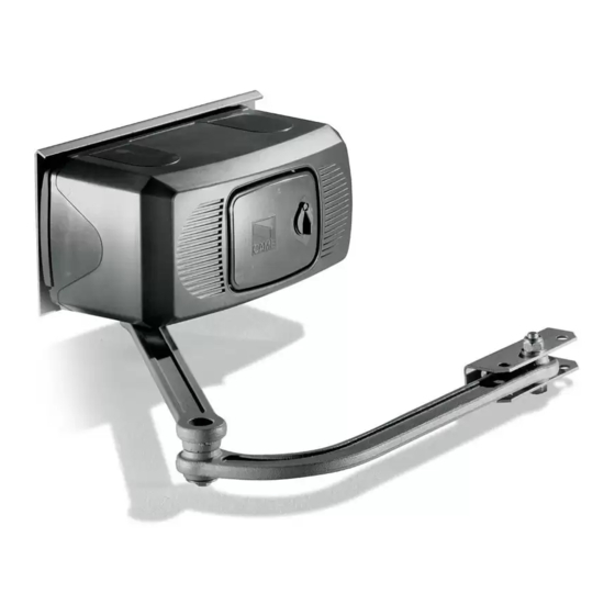
4.3 Descrizione delle parti Piastra di fi ssaggio Motoriduttore Coperchio Braccio di trasmissione snodato Accessorio opzionale: 001F1001 Braccio telescopico diritto di trasmissione per ante fino a 2 m 4.4 Misure d’ingombro 5 Installazione L’ installazione deve essere effettuata da personale qualificato ed esperto e nel pieno rispetto delle normative vigenti. 5.1 Verifiche preliminari Prima di procedere all’installazione dell’automazione è... -
Page 5: Impianto Tipo
5.2 Attrezzi e materiali Assicurarsi di avere tutti gli strumenti ed il materiale necessario, per effettuare l’installazione nella massima sicurezza, secondo le normative vigenti. Di seguito in figura l’attrezzatura minima per l’installatore. 5.3 Tipologia cavi e spessori minimi Tipo Lunghezza cavo Lunghezza cavo Lunghezza cavo Collegamento... - Page 6 5.5 Montaggio - Fissare la piastra di fi ssaggio al pilastro con viti e tasselli rispettando la quota minima di 150 mm dalla pavimentazione. - Fissare la staff a A (con viti o saldatura) all’anta del cancello rispettando le quote di 450 e 19 mm. Pilastro Staffa A Ø...
- Page 7 - Inserire il perno quadro del braccio dritto nell’albero cavo del motore: fi ssarlo con la vite e la rondella e i 2 grani dell’albero cavo. - Aggiungere e fi ssare il braccio curvo con vite e rondella. - Sbloccare il motore (vedi paragrafo) e agganciare il braccio alla staff a A, fi ssandolo con il bullone; verifi care la libera rotazione degli snodi con alcune manovre.
- Page 8 Camma inferiore Per la sucessiva e necessaria regolazione elettronica dello spazio di battuta, consultare la documentazione tecnica del quadro co- mando CAME installato. Dopo aver ultimato le operazioni di montaggio, collegamenti elettrici e regolazioni, procedere a ribloccare il motore ed inserire il coperchio fi...
-
Page 9: Manutenzione Periodica
5.9 Collegamento a quadro comando ZL19N/ZL170N Morsettiera motore Morsettiera quadro comando M -N F -Fa R -Rc Collegamento motore Microinterruttore di fi necorsa in apertura Microinterruttore di rallentamento in chiusura 7 Manutenzione 7.1 Manutenzione periodica Gli interventi periodici a cura dell’utente sono: pulizia dei vetrini delle fotocellule; controllo del corretto funzionamento dei dispositivi di sicurezza;... -
Page 10: Risoluzione Dei Problemi
7.2 Risoluzione dei problemi MALFUNZIONAMENTI POSSIBILI CAUSE VERIFICHE E RIMEDI Il cancello non apre • Manca alimentazione • Verificare la presenza di rete e non chiude • Il motoriduttore è sbloccato • Bloccare il motoriduttore • Il trasmettitore ha la batteria scarica (Cap.5.8) •... -
Page 11: Manutenzione Straordinaria
7.3 Manutenzione straordinaria La seguente tabella serve per registrare gli interventi di manutenzione straordinaria, di riparazione e di miglioramento eseguiti da ditte esterne specializzate. N.B. Gli interventi di manutezione straordinaria devono essere effettuati da tecnici specializzati. Registro manutenzione straordinaria Timbro installatore Nome operatore Data intervento Firma tecnico... -
Page 12: Dichiarazione Di Conformità
UNI EN ISO 14001 a garanzia del rispetto e della tutela dell’ambiente. Vi chiediamo di continuare l’opera di tutela dell’ambiente, che CAME considera uno dei fondamenti di sviluppo delle proprie strate- gie operative e di mercato, semplicemente osservando brevi indicazioni in materia di smaltimento: SMALTIMENTO DELL’IMBALLO... - Page 13 AUTOMATION 1 19D U3 2EN FOR SWING GATES INSTALLATION MANUAL F1024 English...
-
Page 14: Read Carefully
• Employ this product only for the use for which it was expressly made. Any nary maintenance, CALL TECHNICAL ASSISTANCE • Log the job and checks other use is dangerous. CAME S.p.A. is not liable for any damage caused by into the periodic maintenance log. -
Page 15: Legend Of Symbols
4 Description 4.1 Gearmotor This product is engineered and manufactured by CAME S.p.A. and complies with current safety regulations. The gearmotor is composed of two, cast aluminium half shells inside of which rest the gearmotor and endstops – with electro blo- cking –... -
Page 16: Description Of Parts
4.3 Description of parts 1) Base plate 2) Gearmotor assembly 3) Motor cover 4) Articulated transmission arm 4.4 Overall dimensions 5 Installation Installation must be carried out by expert qualified personnel and in full compliance with current regulations. 5.1 Preliminary checks Before installing, do the following: •... -
Page 17: Tools And Materials
5.2 Tools and materials Make sure you have all the tools and materials you will need for the installation at hand to work in total safety and compliance with the current standards and regulations. The following figure illustrates the minimum equipment needed by the installer. 5.3 Cable list and minimum thickness Type of Cable length... - Page 18 5.5 Mounting - Secure the base plate to the pillar using ø8 screws and ø14 moulded inserts making sure the minimum distance of 150mm from the ground is met. - Secure the A bracket (using ø8 screws or by welding) to the gate leaf making sure the 450mm and 19mm distances measurements and are met.
- Page 19 - Insert the straight semi-arm into the motor shaft. Apply the fl ared washer, the M6x20 screw and lock the semi-arm using the two grub screws. Join and secure the two arms using the washer and M8x16 screw. Release the motor (see p. 7) and secure the curved semi-arm to the “A”...
- Page 20 Lower cam When performing the next, required, electronic adjustment of the closing space, please consult the technical documentation of the installed CAME control panel. Once finished with mounting, electrical connections and adjustments, lock the motor back into place and replace the cover securing it with the 4 issued screws.
-
Page 21: Maintenance
5.9 Connecting to the ZL19N/ZL170N control panel Motor terminals Control panel terminal board M -N F -Fa R -Rc Connecting the motor Opening endstop microswitch Closing-speed brake microswitch 7 Maintenance 7.1 Maintenance Periodic maintenance to be carried out by the end-user is as follows: wipe clean the glass surface of the photocells; check that the safety devices work properly;... -
Page 22: Troubleshooting
7.2 Trouble shooting MALFUNCTIONS POSSIBLE CAUSES CHECK AND REMEDIES The gate will not • There is no power • Check that the power is up open nor close • The gearmotor is released • Lock gearmotor (Chapt. 5.8) • The transmitter’s batteries are run down •... -
Page 23: Extraordinary Maintenance
7.3 Extra-ordinary maintenance The following table serves to note down any extraordinary maintenance, repairs or improvements performed by specialised firms. N.B.: Any extraordinary maintenance must be performed by specialised technicians. Extra-ordinary maintenance log Installer’s stamp Operator name Date of job Technician’s signature Requester’s signature Job performed _______________________________________________________________________________________... -
Page 24: Phasing Out And Disposal
CAME S.p.A. employs a UNI EN ISO 14001 certified and compliant environmental protection system at its plants, to ensure that environmental safeguarding. We ask you to keep protecting the environment, as CAME deems it to be one of the fundamental points of its market operations strategies, by simply following these brief guidelines when disposing: DISPOSING THE PACKING MATERIALS The packing components (cardboard, plastic, etc.) are solid urban waste and may be disposed of without any particular difficulty,... - Page 25 AUTOMATISME 11 9DU 32 FR POUR PORTAILS BATTANTS MANUEL POUR L’INSTALLATION F1024 Français...
- Page 26 Toute autre utilisation est à considérer comme correctement. Il s'agit de l'unique opération d'entretien à eff ectuer avec dangereuse. La société CAME S.p.A. décline toute responsabilité en l'automatisme sous tension. Assurer un nettoyage constant des verres cas d'éventuels dommages provoqués par des utilisations impropres, des photocellules (utiliser un chiff on légèrement humidifi...
-
Page 27: Légende Des Symboles
4.00 3 Normes de référence CAME S.p.A. est une entreprise certifiée par le système de Gestion de la Qualité des Entreprises ISO 9001 et de Gestion de l’Environnement ISO 14001. Ce produit est conforme aux règlementations suivantes : voir Déclaration de conformité. -
Page 28: Description Des Parties
4.3 Description des parties 1) Plaque-base 2) Groupe motoréducteur 3) Couvercle moteur 4) Bras de transmission articulé 4.4 Mesure d’encombrement 5 Installation Le montage doit être effectué par du personnel qualifié et expérimenté et dans le respect des normes en vigueur. 5.1 Contrôles préliminaires Avant de procéder au montage, il est nécessaire de: •... -
Page 29: Outils Et Matériel
5.2 Outils et matériel Assurez-vous d’avoir tous les outils et le matériel nécessaire pour effectuer le montage de l’automatisme en toute sécurité et conformément aux normes en vigueur. Sur la planche, quelques exemples de matériel pour l’installateur. 5.3 Types de câbles et épaisseurs minimales Type Longueur câble Longueur câble... -
Page 30: Montage
5.5 Montage - Fixez la plaque-base sur le pilier avec des vis ø8 et des chevilles ø 14 en respectant la cote minimale de 150 mm. du sol. - Fixez l’étrier “A” à la porte du portail (avecvis ø8 ou soudure) en respectant les cotes de 450 et 19 mm. Pilier Étrier “A”... - Page 31 - Insérez le demi-bras droit dans l’arbre carré du moteur. Appliquez la rondelle évasée, la vis M6x20 et bloquez le demi-bras avec les deux grains. Unissez et fi xez les deux bras avec la rondelle et la vis M8x16. Débloquez le moteur (voir page 7) et fi xez le demi-bras courbé...
- Page 32 En fermeture: débloquez le motoréducteur et placez la porte à 500 mm. de la butée d’arrêt en fermeture. Tournez la came inférieure jusqu’à l’introduction du micro-interrupteur et vissez la vis qui se trouve dans cette came.
-
Page 33: Maintenance Périodique
5.9 Connexion armoire de commande ZL19N/ZL170N Bornier moteur Bornier armoire de commande M -N F -Fa R -Rc Connexion moteur Micro-interrupteur de fi n de course en ouverture Micro-interrupteur de ralentissemeent en fer- meture 7 Maintenance 7.1 Maintenance périodique Les opérations périodiques à la charge de l’usager sont : nettoyage des lamelles de verre des photocellules, contrôle de l’état de marche des dispositifs de sécurité, élimination de tout ce qui peut empêcher le fonctionnement conforme de l’automatisme. -
Page 34: Résolution Des Problèmes
7.2 Résolution des problèmes MAUVAIS FONCTIONNEMENT CAUSES POSSIBLES CONTRÔLES ET SOLUTIONS Le portail ne s’ouvre pas et • Il n’y a pas d’alimentation • Vérifiez la présence de réseau il ne se ferme pas • Le motoréducteur est débloqué • Verrouillez le moto réducteur (Chap. 5.8) •... - Page 35 7.3 Maintenance extraordinaire Ce tableau est destiné à l’enregistrement des opérations de maintenance extraordinaire, de réparation ou d’amélioration, effectuées par des entreprises externes spécialisées. N.B. Les opérations de maintenance extraordinaire doivent être effectuées par des techniciens spécialisés. Registre de maintenance extraordinaire Cachet de l’installateur Nom de l’opérateur Date de l’intervention...
-
Page 36: Déclaration De Conformité
UNI EN ISO 14001 pour garantir le respect et la sauvegarde de l’environnement. L’usager est prié de continuer cet effort de sauvegarde de l’environnement que Came considère comme un des facteurs de déve- loppement de ses stratégies de fabrication et commerciales, en suivant ces brèves indications concernant le recyclage: ÉLIMINATION DE L’EMBALLAGE... -
Page 37: Инструкция По Монтажу
АВТОМАТИКА 11 9D U 32R U ДЛЯ РАСПАШНЫХ ВОРОТ ИНСТРУКЦИЯ ПО МОНТАЖУ F1024 Русский... - Page 38 систему на наличие возможных неполадок в работе или других следов назначению. Любое другое применение рассматривается как опасное. износа или повреждений на подвижных конструкциях, компонентах CAME S.p.A. снимает с себя всякую ответственность за возможный автоматической системы, местах крепления, проводке и доступных ущерб, нанесенный в результате неправильного использования...
-
Page 39: Условные Обозначения
Если используется самоблокирующийся привод, монтаж электрозамка является обязательным для створок шириной более 2,5 м. 3. Нормы и стандарты CAME S.p.A. имеет сертификат систем управления качеством ISO 9001 и сертификат охраны окружающей среды ISO 14001. Изделие соответствует требованиям следующих стандартов: смотрите декларацию о соответствии. -
Page 40: Основные Компоненты
4.3 Основные компоненты Монтажное основание Привод Крышка Шарнирный рычаг передачи Опция: 001F1001 Прямой телескопический рычаг передачи для створок шириной до 2 м. 4.4 Габаритные размеры 5. Монтаж Монтаж должен производиться квалифицированным персоналом в полном соответствии с требованиями действующих норм безопасности. 5.1 Предварительные... - Page 41 5.2 Инструменты и материалы Перед началом монтажных работ следует убедиться в наличии всех необходимых инструментов и материалов, которые позволят произвести установку оборудования в полном соответствии с действующими нормами безопасности. Ниже представлен минимальный набор инструментов для монтажника. 5.3 Тип и сечение кабелей Модель...
- Page 42 5.5 Монтаж - Прикрепите монтажное основание к столбу посредством винтов и дюбелей, соблюдая минимальное расстояние от земли 150 мм. - Прикрепите скобу A (с помощью винтов или приварив) к створке ворот, соблюдая расстояния в 450 мм и 19 мм. Столб Передний...
- Page 43 Вставьте штифт квадратного сечения прямого рычага в полый вал привода и зафиксируйте с помощью болта, шайбы и двух установочных винтов полого вала. - Установите и зафиксируйте изогнутый рычаг с помощью винта и шайбы. - Разблокируйте привод (см. соответствующий пункт) и прикрепите изогнутый рычаг к кронштейну A с помощью прилагаемых крепежных...
- Page 44 Микровыключатель Нижний кулачковый механизм Для последующей электронной настройки концевых положений смотрите техническую документацию, прилагаемую к уста- новленному блоку управления CAME. После выполнения работ по монтажу, электрическим под- ключениям и настройке снова заблокируйте привод, уста- новите крышку и зафиксируйте ее с помощью прилагаемых...
- Page 45 5.9 Подключение к блоку управления ZL19N/ZL170N Колодка подключения привода Колодка подключения блока управления M -N F -Fa R -Rc Подключение привода Концевой микровыключатель открывания Микровыключатель закрывания с функцией замедления 7. Техническое обслуживание 7.1 Периодическое техническое обслуживание, осуществляемое пользователем Пользователем должны периодически выполняться следующие работы: чистка фотоэлементов, контроль за правильной...
-
Page 46: Возможные Неисправности И Способы Их Устранения
7.2 Возможные неисправности и способы их устранения НЕИСПРАВНОСТЬ ВОЗМОЖНАЯ ПРИЧИНА СПОСОБ УСТРАНЕНИЯ Створка ворот не • Нет напряжения питания. • Включите электропитание. двигается. • Разблокирован привод. • Заблокируйте привод (раз- • Разрядились батарейки брелока-передатчика. дел 5.8). • Сломан брелок-передатчик. • Замените батарейки. •... - Page 47 7.3 Внеплановое техническое обслуживание Эта таблица необходима для записи внеплановых работ по обслуживанию и ремонту оборудования, выполненных специализированными предприятиями. Важное примечание: ремонт оборудования должен осуществляться квалифицированными специалистами. Бланк регистрации работ по внеплановому техническому обслуживанию Место печати Компания Дата проведения работ Подпись...
- Page 48 8. Утилизация CAME S.p.A. имеет сертификат системы защиты окружающей среды UNI EN ISO 14001, гарантирующий экологиче- скую безопасность на ее заводах. Мы просим, чтобы вы продолжали защищать окружающую среду. САМЕ считает одним из фундаментальных пунктов стратегии рыночных отношений выполнение этих кратких руководящих принципов: УТИЛИЗАЦИЯ...
Need help?
Do you have a question about the F1024 and is the answer not in the manual?
Questions and answers