Table of Contents
Advertisement
Quick Links
• FX150 series
• FX300 series
• MTTplus-410 series
• RXT-41xx series
• TX3x0S series
• OTDR Viewer
Please direct all questions to your local VeEX
Or, contact VeEX technical support at www.veexinc.com.
No part of this user manual may be reproduced, translated into a foreign language, or
be transmitted electronically without prior agreement and written consent of VeEX
Incorporated as governed by International copyright laws. Information contained in this
manual is provided "as is" and is subject to change without notice. Trademarks of VeEX
Incorporated have been identified where applicable, however the absence of such
identification does not affect the legal status of any trademark.
Copyright 2020 VeEX Incorporated. All rights reserved.
OTDR Series
Sales Office, Representative, or Distributor.
®
USER MANUAL
D07-00-076P RevE00
Advertisement
Table of Contents

Related Manuals for VeEX OTDR Series


Summary of Contents for VeEX OTDR Series
- Page 1 VeEX Incorporated as governed by International copyright laws. Information contained in this manual is provided “as is” and is subject to change without notice. Trademarks of VeEX Incorporated have been identified where applicable, however the absence of such identification does not affect the legal status of any trademark.
-
Page 2: Table Of Contents
......................32 LEANING ROCEDURE ........................33 RACTICES ........................... 34 ONNECTORS 6.5.1 Connector Types ..........................34 6.5.2 Connector Performance and Polishing....................36 .................. 38 IBER ABLES AND IBER ATCHCORDS 6.6.1 Fiber Cable ............................38 OTDR Series e-Manual, RevE00 Page 2 of 128... - Page 3 LOUD REDENTIALS ........................88 ISPLAY PTIONS OTDR: Making Measurements ................89 ............................ 90 VENTS 8.1.1 Event Table ............................90 8.1.2 Event Types ............................92 8.1.3 Event Editing ............................93 .......................... 94 EASURE OTDR Series e-Manual, RevE00 Page 3 of 128...
- Page 4 OTDR T ) ................118 IDIRECTIONAL ESTING VIEW ..........................123 BOUT File Management ....................124 9.1.1 Saving/Printing Results to PDF/USB/Bluetooth ................125 10.0 Certifications and Declarations ................127 11.0 About VeEX ......................128 OTDR Series e-Manual, RevE00 Page 4 of 128...
-
Page 5: About This User Manual
VeEX Inc., and to use it solely as intended and described in this manual. The purchaser is prohibited from copying, reverse engineering, decompiling, or disassembling the software. -
Page 6: Warranty
To activate the warranty, please register your product at https://www.veexinc.com/Support/ProductRegistration. Patent Information VeEX product hardware and software may be protected by one or more patents on file with the United States Patent Office. Documentation Conventions Icons used in this manual: Marks a helpful tip (action or method), which can save time and improve usability of the product. -
Page 7: Product Introduction
• Wireless and Bluetooth options (FX150 standard; FX300/MTTplus/TX3x0S/RXT optional; see platform’s datasheet for details/availability at www.veexinc.com): • Software upgrades and uploading test data via wireless connection • Pairing applications with Mobile Smartphones, Tablets, Windows PCs, and OPX- BOXe units. OTDR Series e-Manual, RevE00 Page 7 of 128... -
Page 8: Key Features
• Auto mode with automated trace diagnostics, simplified setup and events detection • Optional V-Scout Profile test mode – Intelligent Link Mapping using intuitive icons derived user defined Profiles that allow multiple test acquisitions OTDR Series e-Manual, RevE00 Page 8 of 128... -
Page 9: Package Contents
• Input: 100-240 VAC (50/60 Hz), 1.5A max (RXT1200/TX3x0S); 5.3A max (MTTplus); 1.5A max (FX150) • Output: 16VDC (RXT1200/TX3x0S); 15VDC (MTTplus); 12VDC (FX150) • Li-Ion or Li-Polymer battery (capacity depends on platform) • Nylon Soft Carry case (optional) OTDR Series e-Manual, RevE00 Page 9 of 128... -
Page 10: Safety Information
Do not operate the instrument in the presence of flammable gases or fumes or any other combustible environment. VeEX Inc. assumes no liability for the customer's failure to comply with safety precautions and requirements. -
Page 11: Theory Of Operation
After several cycles, the obtained signal values are transferred from RAM and displayed. Then, the process of measuring, averaging, and cleaning RAM registers is repeated again. OTDR – Principle of Operation OTDR Series e-Manual, RevE00 Page 11 of 128... -
Page 12: Light Source
The OPM will support both MM and SM fiber with the APC or UPC connector type. WaveID can be enabled to detect source wavelength automatically when used with VeEX light sources that also support WaveID. For more information on specifications, see the datasheet. -
Page 13: Basic Operation
The optical fiber connector must be cleaned prior to connecting to the fiber under test. Dust and dirt severely impact optical performance. For more information on fiber handling procedures and tip cleaning, see Section 6.0 Test Fiber and Initial Preparation Introduction. OTDR Series e-Manual, RevE00 Page 13 of 128... - Page 14 TX3x0S Top View RXT-4100 OTDR Module OTDR Series e-Manual, RevE00 Page 14 of 128...
-
Page 15: Front Panel Layout
Utility menu • LED History Key: Resets LED condition (depends on test application) • Save Trace/Result Key: Saves test result file (OTDR, OPM, Ethernet, Fiberscope - depends on active application and unit configuration) OTDR Series e-Manual, RevE00 Page 15 of 128... -
Page 16: Menu Navigation
The touchscreen can be recalibrated when needed. For more information, see the platform user manual at www.veexinc.com. OTDR Series e-Manual, RevE00 Page 16 of 128... -
Page 17: Mttplus Overview
MTTplus Overview 5.3.1 MTTplus Side View OTDR Series e-Manual, RevE00 Page 17 of 128... -
Page 18: Mttplus Control Panel
Requires the camera (factory-installed option). Upgrading Platform Software To upgrade the platform software, simultaneously press and HOLD the Camera and Power keys until the unit beeps. 5.3.3 MTTplus OTDR Module Top View OTDR Series e-Manual, RevE00 Page 18 of 128... -
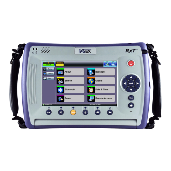
Page 19: Rxt Overview
RXT Overview OTDR Series e-Manual, RevE00 Page 19 of 128... -
Page 20: Rxt Front Panel
• Lock/Unlock Touch Screen: Can also be programmed to capture screen shots (>Utilities >Settings>Global>Save Settings) • Home: Returns to the Main Menu • Save Test Results: In OTDR test mode, selects the Results tab. OTDR Series e-Manual, RevE00 Page 20 of 128... -
Page 21: Getting Started
This screen can be displayed at any time from any screen. The test port group is assigned to the Fiber application when the MTTplus 410 or RXT-41xx OTDR module is installed. All options associated with the OTDR module will be installed. OTDR Series e-Manual, RevE00 Page 21 of 128... -
Page 22: Fx150 Overview
• Power: Press for 2 seconds to turn the test set ON or OFF (prevents accidental ON/OFF). • Home: Resets user interface to Main menu. • Right side + Save: Saves the screen (bmp). • Right side + Home: Hibernates device. OTDR Series e-Manual, RevE00 Page 22 of 128... -
Page 23: Fx150 Screen Navigation
• IP address, when connected • Remote control connection status • Date and time • Bluetooth and WiFi connection indicators For all available chassis operations, see the V150 Common Functions User Manual on www.veexinc.com. OTDR Series e-Manual, RevE00 Page 23 of 128... -
Page 24: View/Hide Side Menu Panels
Real Time OTDR – See trace in real time. Fiber Scope – Shortcut key to access Fiber Scope. This icon appears on the right menu automatically when a Fiber Scope is detected. OTDR Series e-Manual, RevE00 Page 24 of 128... -
Page 25: Setting Up Wifi (Optional Feature)
OTDR traces and software upgrades on the unit. For other models, WiFi or Bluetooth options are available using WiFi and/or Bluetooth dongles. 5.5.4.1 Access WiFi option 1. Tap Utilities or the green HOME key, and then tap Bluetooth/WiFi. 2. Select the WiFi Wiz tab. OTDR Series e-Manual, RevE00 Page 25 of 128... -
Page 26: Connect To A Wifi Network
Access Point but will not be able to connect to the web or perform the Ping test. Built-in web browser remote control is available when WiFi is enabled. OTDR Series e-Manual, RevE00 Page 26 of 128... -
Page 27: Customizing Your Tester (See Platform User Manual For Details)
SAVE + HOME keys simultaneously for 3 seconds, then releasing. Press SAVE + HOME again to start a new calibration. • Bluetooth/WiFi: Setup and scan Bluetooth and/or WiFi. See the V150 Common Functions Manual on www.veexinc.com for more details. OTDR Series e-Manual, RevE00 Page 27 of 128... - Page 28 • NTP Time Service: (optional) Turn ON to allow the test unit periodically to obtain the current time from a public time server. Whenever the test set is connected to the Internet, the time will be updated. OTDR Series e-Manual, RevE00 Page 28 of 128...
- Page 29 • More: Additional options including: • Remote Access: Settings for accessing and/or controlling the test set and the information it contains using the VeEX ReVeal software or VNC Server/Viewer. For more information on Remote Access, see the V150 Common Functions Manual on www.veexinc.com.
-
Page 30: Test Fiber And Initial Preparation Introduction
Contamination of fiber end faces affecting optical power levels OTDR Series e-Manual, RevE00 Page 30 of 128... -
Page 31: Contamination
It is recommended to wear laser safety glasses when you work with fiber-optic connections, and always check that you disconnect the laser or transmitter before you begin cleaning the connector end faces. OTDR Series e-Manual, RevE00 Page 31 of 128... -
Page 32: Cleaning Procedure
First spray into the air, as the initial stream of compressed air could contain some condensation or propellant. Such condensation leaves behind a filmy deposit. OTDR Series e-Manual, RevE00 Page 32 of 128... -
Page 33: Best Practices
• It is recommended to re-inspect the bulkhead receptacles and connector end face using a fiber microscope following the cleaning and prior to use. • The flow diagram below describes a best practice prior to connecting your optical fiber. OTDR Series e-Manual, RevE00 Page 33 of 128... -
Page 34: Connectors
FC is the fiber optic connector standard for Nippon Telephone & Telegraph (NTT) installations, developed with Nippon Electric Co. (NEC). The FC screws on firmly, but make sure the key is aligned in the slot properly before tightening. OTDR Series e-Manual, RevE00 Page 34 of 128... - Page 35 2.5mm ferrule, and molded housing for protection. The SC is a snap-in connector that is widely used in singlemode systems due in part for its performance. The snap- in connector latches with a simple push-pull motion. OTDR Series e-Manual, RevE00 Page 35 of 128...
-
Page 36: Connector Performance And Polishing
The smooth curve in the PC style is designed to reduce the return loss by reflecting the light out of the fiber. However, the PC polishing style incurs more return loss than other styles. OTDR Series e-Manual, RevE00 Page 36 of 128... - Page 37 Connector Polish and Performance Typical Return loss values are: • Polished Connector ~ -45dB • Ultra-Polished Connector ~ -55dB • Angled Polished Connector up to ~ -65dB OTDR Series e-Manual, RevE00 Page 37 of 128...
-
Page 38: Fiber Cables And Fiber Patchcords
• 2, 4, 6, 8, 12, 24, 48, 72 or greater fiber counts Outer Jacket can be of a variety of materials • Terminated with all styles of connectors • Often field terminated Distribution • Both Multimode and Singlemode • Indoor / Outdoor applications • 900um subunits OTDR Series e-Manual, RevE00 Page 38 of 128... -
Page 39: Fiber Patchcord
• Fiber type – singlemode, multimode or ribbon • Connector type (ST, SC, FC, LC, E2000, MTP/MPO, etc.) • Dead-zone requirements (Refer to Section 4.2) Back reflection performance • Insertion Loss • Durability and Longevity • Bend Limitation OTDR Series e-Manual, RevE00 Page 39 of 128... - Page 40 Angle Polished (APC), 8° Singlemode only, not available for multimode fibers Black Physical Contact (PC), 0° White Physical Contact (PC), 0° High optical power. Sometimes used to connect external pump lasers or Raman pumps OTDR Series e-Manual, RevE00 Page 40 of 128...
-
Page 41: Inserting The Fiber
Mismatched connector types will damage the optical end faces and the test set. If the optical fiber is not aligned properly and/or completely connected, it will cause serious loss and reflection. OTDR Series e-Manual, RevE00 Page 41 of 128... -
Page 42: Fiber Scope Utility
The Optical Power Meter app is for the UPM-100 USB dongle option or FX4x OPM tethered to device using USB cable. The FX150 will detect when a Fiber Scope is connected automatically. A shortcut icon will be displayed on the right-side menu. OTDR Series e-Manual, RevE00 Page 42 of 128... -
Page 43: Fiber Scope Setup
• Scope mode: Select Local (USB connect) or Remote (WiFi connect not available) operation. • Auto Save: Select Disabled, Enabled, Enabled+Report (pdf) or Enabled+V-Scout Report (l • Ask Before Save: Check this to be prompted to save after test is complete. OTDR Series e-Manual, RevE00 Page 43 of 128... - Page 44 • Tip type: Select the type of tip used on the Fiber Scope. General is the default type. LC/APC and E2000/APC should not use general tip type. • Auto center/Crop: Check this to center and crop the image automatically. This is ideal for APC images. OTDR Series e-Manual, RevE00 Page 44 of 128...
-
Page 45: Hardware And Software Settings
Focus. The default is set to OFF. To see the image after it freezes, tap Resume. • Rectangles / Dots: Dots draw a red contour around scratches and defects. Rectangles highlight scratches and defects without obstructing the view. OTDR Series e-Manual, RevE00 Page 45 of 128... - Page 46 The spotlight ON/OFF, image contrast Up/Down buttons, and Freeze/Save buttons are on top. For more instructions on using the Fiber Scope, see the Fiber Scope User Manual on www.veexinc.com. OTDR Series e-Manual, RevE00 Page 46 of 128...
-
Page 47: Connector Face Analysis
Select Page 2 of 2 view in the Capture tab. The test set displays a table with all numeric results from the analysis. Catalogs, Defect and Scratch events found for all four zones. Scratch requirements refer to width. This table will also be included in the reports. OTDR Series e-Manual, RevE00 Page 47 of 128... -
Page 48: Result Files
• Pull: When connected, pulls file from Fiberizer Cloud onto test set. • USB Export: Exports files to USB stick. Choose Export Group to retain the tree format (sub-directory) or Export Flat to create a single filename using sub-directories to build a name. OTDR Series e-Manual, RevE00 Page 48 of 128... -
Page 49: Test Analysis Report
JPG format or exported to PDF. In addition, all fiber optic test results can be viewed using Fiberizer Cloud or the Fiberizer Desktop Plus PC software. For more information on viewing reports, Section 6.8.9 Managing Fiberscope Results with File Manager. Analysis Report (.jpg format) OTDR Series e-Manual, RevE00 Page 49 of 128... - Page 50 Analysis Report (.pdf format) OTDR Series e-Manual, RevE00 Page 50 of 128...
-
Page 51: Managing Fiberscope Results With File Manager
To backup and restore files, use a USB Memory stick. • To USB: Copies all selected files to the stick. • From USB: Restores all files from the stick. • BT: (Bluetooth®) File Transfer the requires compatible USB dongle. OTDR Series e-Manual, RevE00 Page 51 of 128... -
Page 52: File Manager Filters
To make locating test results and reports easier, sort the results by tapping a header to sort by that field’s type, in ascending or descending order. 6.8.10 Fiber Scope Image Management Software For information on using Fiber Scope Management Software, see the Fiber Scope User Manual on www.veexinc.com. OTDR Series e-Manual, RevE00 Page 52 of 128... -
Page 53: Visual Fault Locator (Vfl)
Home icon (FX150/RXT) to toggle between active tests (OTDR, OLS, OPM, VFL). App key (FX300) to toggle between active tests (OTDR, OLS, OPM, VFL). Use the VFL can be used with OTDR simultaneously. OTDR Series e-Manual, RevE00 Page 53 of 128... -
Page 54: Using The Vfl
3. Power ON the unit, and then tap the X icon to close OTDR mode and display the Fiber Main Menu. 4. Tap Visual Fault Locator on the main menu. The Caution screen appears. Visual Fault Locator menu option VFL: Caution screen OTDR Series e-Manual, RevE00 Page 54 of 128... - Page 55 When not in use, disconnect the cord from the port, replace dust covers, and keep the port cap securely closed. VFL will not work on G.655 bend insensitive patchcords or cables with dark jacketing material or armored cables. OTDR Series e-Manual, RevE00 Page 55 of 128...
-
Page 56: Optical Light Source (Ols)
On the RXT, if the Fiber Main Menu does not appear tap Fiber at the top. 3. Tap Optical Light Source on the main menu. The OLS screen appears with the Caution warning. Optical Light Source menu option OTDR Series e-Manual, RevE00 Page 56 of 128... - Page 57 • 270 Hz, 1000 Hz, 2000 Hz (Pulse). Select this option to send intermittent light pulses. In some cases, this makes it easier to identify faults (than continuous light). It can also be used with audible detectors (toners) that can identify faint light or in well-lit (bright) environments. OTDR Series e-Manual, RevE00 Page 57 of 128...
-
Page 58: 6.10.2 Using The Optical Light Source
The RXT-4111 DWDM OTDR test module offers advanced TEC laser stabilization for hot and color weather operating conditions. If the optimal temperature for usage has not been reached, a Laser Stabilization message appears. Laser Stabilization message OTDR Series e-Manual, RevE00 Page 58 of 128... -
Page 59: Optical Power Meter (Opm)
Use the • Only optical power meters (e.g. Built-in, UPM-100 or FX4x/8x OPM series meters) approved by VeEX are supported. WaveID will work with OLS in CW mode only. • Accessing the Optical Power Meter module shuts down GPS and the atomic service. -
Page 60: 6.11.2 Configure The Opm
4. Tap Set to record the 0.00 dB point. A reference point is established and the calibrated LS can be connected to the far-end of the fiber to measure the loss. Tapping Set will overwrite previously saved reference value(s). OTDR Series e-Manual, RevE00 Page 60 of 128... -
Page 61: 6.11.2.2 Opm Options
When in doubt, perform this procedure prior to making any measurements. For example, when you are testing in cold outdoor temperatures and then move testing inside to a heated building. Put the cover over the OPM test port BEFORE recalibrating. OTDR Series e-Manual, RevE00 Page 61 of 128... -
Page 62: 6.11.3 Using The Opm
For more information, see Section 6.12 Table Section 6.13 Results. 7. When testing is complete, tap OPM server on to power down the OLS, and then disconnect the cable and replace the port covers. OTDR Series e-Manual, RevE00 Page 62 of 128... -
Page 63: 6.12 Table
To remove results before saving, select the check box next to the reading(s), then tap Remove. After saving power or loss readings to a file, access the file in the Results tab. OTDR Series e-Manual, RevE00 Page 63 of 128... -
Page 64: 6.13 Results
• Pull: When connected, pulls file from Fiberizer Cloud onto the test set. • USB Export: Exports files to a USB stick. • Save continuously: To autosave results at a specified interval (1 to 60 seconds). Use this option to check power drift. OTDR Series e-Manual, RevE00 Page 64 of 128... - Page 65 To push the results to Fiberizer Cloud, ensure connection to the network via Ethernet or WiFi, and then tap Modify>Settings to sync with Fiberizer Cloud. Then, tap Push to sync saved files to the cloud. Fiberizer Cloud set up screen OTDR Series e-Manual, RevE00 Page 65 of 128...
-
Page 66: Otdr Setup
• DWDM Grid (RXT-4111) – Select the test wavelength. • XWDM Grid (RXT-4113) - Select CWDM or DWDM (50, 100, or 200GHz) • CWDM Unit (RXT-4113) – Select the test wavelength. • DWDM Channel (RXT-4113) – Select the test channel. OTDR Series e-Manual, RevE00 Page 66 of 128... -
Page 67: Test Parameters
Real Time, Auto Real Time, V-Scout Profiles or MPO Auto (with OX-MPO-12 optical switch connected). 7.2.1 Manual Mode To set OTDR test parameters manually, under Test Parameters select Manual from the Mode drop-down menu. OTDR Test Setup: Manual Mode OTDR Test Setup: RXT-4113 Manual Mode OTDR Series e-Manual, RevE00 Page 67 of 128... -
Page 68: Auto Mode
To set OTDR test parameters automatically, under Test Parameters select Auto from the Mode drop-down box. In this mode, the OTDR performs a measurement and analysis of the fiber and determines optimal test settings automatically. OTDR Setup: FX150 Auto mode OTDR Series e-Manual, RevE00 Page 68 of 128... - Page 69 • Auto PON - Point-to-MultiPoint where software will assign splitter types based on event loss. (Connect at Customer site.) • Auto PON to ONT: Ideal for fiber monitoring when connected at OLT site. Recommend 50dB dynamic range. OTDR Series e-Manual, RevE00 Page 69 of 128...
-
Page 70: Other Parameters
BC (Backscattering coefficient, BC): Represents level of backscattering in a particular fiber. It is used for Reflectance and ORL measurement and can be obtained from the fiber manufacturer. Backscattering coefficient can be changed for any stored trace. OTDR Series e-Manual, RevE00 Page 70 of 128... -
Page 71: Thresholds
(Default) or to enter custom settings (Custom). Events will be placed into the table only if the Analysis threshold is met/exceeded. Events that fail to meet the Pass/Threshold will be flagged and highlighted as red in the event table. OTDR Series e-Manual, RevE00 Page 71 of 128... -
Page 72: Analysis Thresholds
2 dB in 0.1 dB increments. The default value is 0.2dB. • Show Fiber Sections – Shows fiber section in event table. • Distance Unit – Sets unit to be used for all length measurements (km, kft, feet, meter, miles). OTDR Series e-Manual, RevE00 Page 72 of 128... -
Page 73: Splitter Thresholds
Pass/Fail Thresholds values can be set for each test wavelength. Event Loss (splice, connectors, mux) and Reflectance threshold settings determine if a detected anomaly should be reported and included in the event table including its event type (reflective or non-reflective). OTDR Series e-Manual, RevE00 Page 73 of 128... - Page 74 • Fiber Length (km, miles) - Total fiber length that exceeds set value. To modify values, select the P/F threshold from the drop-down list. Then, tap Modify to Fill, Add, Rename, or Remove values. OTDR Series e-Manual, RevE00 Page 74 of 128...
-
Page 75: Span Settings
If a launch fiber is used at the far end of the test fiber, set the Span End Index to the Event # associated to the location where the far end launch fiber starts. OTDR Series e-Manual, RevE00 Page 75 of 128... -
Page 76: Measure Cables
2. Select which cable (Launch only, Receive only, or Launch and Receive) to measure. To measure both cables (Launch and Receive), connect the cables together, but this requires a connection to have -55dB reflectance. Then, click OK. The Launch and Receive Cable Measurement screen is displayed. OTDR Series e-Manual, RevE00 Page 76 of 128... - Page 77 Calibration (Span settings) screen. If the Launch and Receive option is selected and the cables are not connected, you will receive a “Can’t find the R>=-55dB coupling event, try measuring each cable individually”. OTDR Series e-Manual, RevE00 Page 77 of 128...
-
Page 78: V-Scout (Custom Profiles)(Optional)
Using V-Scout Mode To setup or modify V-Scout custom profiles: 1. On the Setup screen, select V-Scout for Mode, then tap the V-Scout button. The V-Scout Profiles screen appears. V-Scout Profiles Screen OTDR Series e-Manual, RevE00 Page 78 of 128... - Page 79 • To rename the profile, tap Modify and then tap Rename to change the profile name. • To remove a profile, tap Modify and then tap Remove. 4. In the Profile drop-down list box, select the V-Scout Profile configured previously. OTDR Series e-Manual, RevE00 Page 79 of 128...
- Page 80 If Ask Before Save was not checked, results will be saved automatically using the parameters previously set for AutoSave. 5. When the V-Scout test plan is complete and OTDR traces performed, view the V-Scout link map on the LinkMap tab. OTDR Series e-Manual, RevE00 Page 80 of 128...
-
Page 81: V-Scout Linkmap
• Span: To redefine the Span Start/End, select the Event, then click Span and choose the applicable option, Span Begin, Span End, or Edit (to change Span setup details). • Information: Displays measurement information. To view contents of a merged event, double-tap the LinkMap or Event table. OTDR Series e-Manual, RevE00 Page 81 of 128... - Page 82 1x128, 2x2, 2x4, 2x8, 2x16, 2x32, 2x64, or 2x128 Splitter (when Manual PON type is selected): Not present, 1x2, 1x4, 1x8, 1x16, 1x32, 1x64, 1x128, 2x2, 2x4, 2x8, 2x16, 2x32, 2x64, or 2x128 OTDR Series e-Manual, RevE00 Page 82 of 128...
-
Page 83: V-Scout Symbols
Threshold measured at different wavelengths Several aggregated or grouped events 1xN Splitter from the OLT side Loss > 4dB, Reflectance not applicable 1xN Splitter from the ONT (end-user) side Loss > 4dB, Reflectance not applicable OTDR Series e-Manual, RevE00 Page 83 of 128... -
Page 84: Autosave Parameters
• Trace ID - Select Add Index to auto-increment or select Add Date/Time. The filename will include details entered in this field automatically. The fiber count can be incremented in Trace ID or Fiber ID. OTDR Series e-Manual, RevE00 Page 84 of 128... - Page 85 • Node ID: Node ID • Account: Account number • Tech ID: Operator ID (automatically populated when synchronized with R-Server) • Tech Name: Operator name (automatically populated when synchronized with R- Server) OTDR Series e-Manual, RevE00 Page 85 of 128...
- Page 86 To view or export a saved result, select the Results tab. For more details on the Results tab, Results. Alternatively, files can be accessed by selecting Section 8.5 Utilities>Files>Saved on the Home menu. OTDR Series e-Manual, RevE00 Page 86 of 128...
-
Page 87: Cloud Credentials
• Reset: Resets the Cloud account and Project information on the screen. After setting up the Cloud Parameters, test results can be pushed to the account on the Cloud. For more information, see Section 8.5 Results. OTDR Series e-Manual, RevE00 Page 87 of 128... -
Page 88: Display Options
• Auto Zoom Trace: Use this mode to auto scale the viewing window at the end of the test. Disable this option when using Realtime test mode. • Distance Unit: Select the distance unit type for fiber length (Kilometers, Meters, Kilofeet, Feet, or Miles) OTDR Series e-Manual, RevE00 Page 88 of 128... -
Page 89: Otdr: Making Measurements
V-Scout traces are overlaid and displayed automatically. Home icon to return to the Fiber Main Menu to select test application (OTDR, VFL, Use the OLS, OPM). OTDR Series e-Manual, RevE00 Page 89 of 128... -
Page 90: Events
The Events table is available in all measurement modes. Select the Events tab to display the trace with events. The Event table displays all events found during the analysis including those added manually. To view contents of a merged event, double-tap the Event table. Event Table (RXT-4113) OTDR Series e-Manual, RevE00 Page 90 of 128... - Page 91 (Span End) is the end. The reported total loss and ORL is from this area of the trace only. For example, if there is a 1000m launch cable between the OTDR and FUT, then the Span Start of 0km is set at the end of 1000m. OTDR Series e-Manual, RevE00 Page 91 of 128...
-
Page 92: Event Types
The Event is color coded depending on Threshold settings defined in the test setup (see Section 7.3.1 Threshold. • Red indicates the event fails or exceeds the Pass threshold criteria. • Green indicates the event passes the Fail threshold criteria. OTDR Series e-Manual, RevE00 Page 92 of 128... -
Page 93: Event Editing
Span End (if launch box is used). • Markers - Brings a marker onto the visible area of the display. • Event – Add, delete, or make manual adjustments to the event table and reanalyze. OTDR Series e-Manual, RevE00 Page 93 of 128... -
Page 94: Measure Tab
The Marker is divided into a thick (bottom) and thin (top) line. To move Marker A or Marker B individually, select and drag the Marker on the thin portion of the marker. To move both Markers together, select and drag any Marker on the thick portion of the line. OTDR Series e-Manual, RevE00 Page 94 of 128... -
Page 95: Zoom/Scroll Controls
The mode resets to Zoom immediately after one scroll operation has been completed. • Zoom Out - Resets display area. • Zoom Lock - Locks horizontal and vertical controls so zoom aspect is kept uniform. OTDR Series e-Manual, RevE00 Page 95 of 128... -
Page 96: Distance Measurements
Loss Modes - Several Loss modes are available for manual measurements depending on measurement application: • 2-Pt Loss • 2-Pt LSA Two Point Loss measurement • Reflectance • ORL (Optical Return Loss) • Splice Loss OTDR Series e-Manual, RevE00 Page 96 of 128... -
Page 97: Two Point Loss (2-Pt Loss)
• Distance between marker A and B (km, miles, feet) • Level difference in dB • Attenuation based loss/distance When using Realtime test mode, use the 2-Point LSA method to stabilize loss values. OTDR Series e-Manual, RevE00 Page 97 of 128... -
Page 98: Splice Loss Measurement
The sections between the first two markers and the last two markers are approximated by straight lines (LSA). The value of event loss is defined by the position of the center marker. OTDR Series e-Manual, RevE00 Page 98 of 128... -
Page 99: Reflectance Measurement
• Distance of A cursor (reflection) from Start of test fiber • Distance of B cursor (top of reflection) from Start of test fiber • Distance between markers A->B • Reflection for this even (-dB) OTDR Series e-Manual, RevE00 Page 99 of 128... -
Page 100: Orl Measurement
The bottom of the screen displays: • Distance to A cursor • Distance to B cursor • Distance between markers A-B • Loss between the markers A-B (dB) • Optical Return Loss (ORL), dB OTDR Series e-Manual, RevE00 Page 100 of 128... -
Page 101: Mpo Fiber Testing
The OX-MPO-12 optical switch is an ultra-compact, 12 fiber optical switch designed to operate with VeEX OTDRs via USB interface. It is optimized for high-density fiber test applications where MPO/MTP or ribbon cables need to be tested using an OTDR equipped with a single fiber output. -
Page 102: Ox-Mpo-12 Connections/Ports
• MPO/APC on both ends (MPO/APC FUT). • MPO/APC to simplex cable fanout 2x (SC-APC, SC-UPC, FC-APC, FC- UPC, LC-APC, LC-UPC…) to test simplex FUT cable. Contact VeEX Customer Care for more information. OTDR Series e-Manual, RevE00 Page 102 of 128... -
Page 103: Using The Mpo Switch
Measure tab screen appears. The measurement will begin according to the test parameters entered in the Setup menu (see Setup). For more information about making Section 7.0 OTDR measurements, see Section 8.0 OTDR: Making Measurements. OTDR Series e-Manual, RevE00 Page 103 of 128... -
Page 104: Testing Individual Mpo Fibers
8.3.3.2 Testing Individual MPO Fibers To test individual MPO fibers: 1. On the OTDR’s Home Screen, select the Expert OTDR option. 2. Select the wavelengths to test (1310 and/or 1550 nm). OTDR Series e-Manual, RevE00 Page 104 of 128... - Page 105 8 or 12. Each fiber strand is represented by a circle. A black inner circle indicates an active fiber strand and a gray inner circle means inactive. 4. Move the blue arrow above the circles left or right and tap to enable testing for this MPO group. OTDR Series e-Manual, RevE00 Page 105 of 128...
- Page 106 6. To view all MPO strands, select the Traces tab and then select all fibers under the MPO group to overlay results for the ribbon. For more information about the Traces tab, see Section 8.4 Traces. OTDR Series e-Manual, RevE00 Page 106 of 128...
-
Page 107: Traces
Trace Information window, containing the following information relating to the saved file: • Device: OTDR supplier name, Mainframe ID and serial #, and optical module serial # (if applicable) OTDR Series e-Manual, RevE00 Page 107 of 128... - Page 108 Originating/Terminating locations, and Comments • Measurement: Test parameters used to make measurement. Trace Information - Measurement • Thresholds: Analysis thresholds used to analyze the trace, as well as PON identification for LinkMap. OTDR Series e-Manual, RevE00 Page 108 of 128...
- Page 109 4. Tap OK to apply changes. All changes will be applied immediately. 5. After carefully noting the JobID/CableID/FiberID/TraceID fields, save the trace. The Job/Cable/Fiber/Trace determine the location to which the trace is saved. For multi-wavelengths/multi-pulsewidths, edit change trace separately. OTDR Series e-Manual, RevE00 Page 109 of 128...
-
Page 110: Saving Otdr Traces
If these settings are not set accurately, the trace will not save to the desired location. To save Traces: 1. On the Results tab, select the trace you want to save. 2. Click Save, then click Save. The Result Saving window appears. OTDR Series e-Manual, RevE00 Page 110 of 128... - Page 111 3. If needed, change default information on the General, Other, and Report tabs, and then click OK. To view or print reports, use the File Management feature or one of the Fiberizer software applications. For more information, see Section 9.0 File Management. OTDR Series e-Manual, RevE00 Page 111 of 128...
-
Page 112: Third Party Viewers
When third party viewing is checked, the OTDR saved results include a filter so that third party software will display OTDR traces identical to how VeEX test sets display them. Once saved in this format with the third party filter applied, it cannot be changed afterwards. -
Page 113: Embedded Gps And Camera Image
Adding GPS to OTDR file (optional feature) The GPS coordinates can be added by using: • AutoSave: Select the Ask Before Save check box. • Manual Save mode: Select the GPS check box. OTDR Series e-Manual, RevE00 Page 113 of 128... -
Page 114: Adding Camera Image Otdr File (Mttplus Only)
1. Select the Add Image to pop up the camera image. 2. Select red Camera button to capture results. MTTplus: Camera button or select red X button to exit Camera capture mode. OTDR Series e-Manual, RevE00 Page 114 of 128... - Page 115 3. Click the green OK button to finalize the save process. MTTplus Manual Save: Image added to results OTDR Series e-Manual, RevE00 Page 115 of 128...
-
Page 116: Results
Alternatively, access and export files to a USB memory device by tapping Utilities>Files>Saved, then To USB. Each trace will be saved in a separate file folder. See Section 9.1.1 Saving/Printing for details. Results to PDF/USB/Bluetooth OTDR Series e-Manual, RevE00 Page 116 of 128... - Page 117 Results tab: Wavelength/Trace OTDR Series e-Manual, RevE00 Page 117 of 128...
-
Page 118: Bidirectional Otdr Testing (X-View)
• Reset or Force the Trace Index counter number to the fiber port you are testing at; otherwise, it will continue incrementing from the previous test. To change the number, tap Trace Index. OTDR Series e-Manual, RevE00 Page 118 of 128... - Page 119 • Reset or Force the Trace Index counter number to the fiber port you began testing at; otherwise, it will continue incrementing from the previous test. To change the number, tap Trace Index. Bidirectional Trace – Reverse Direction testing OTDR Series e-Manual, RevE00 Page 119 of 128...
- Page 120 (e.g. load “Origin_End” and “End_Origin”). See step 3. 3. On the Results tab, select the required traces and tap Load. Bidirectional testing: Results tab Bidirectional View: First Trace loaded (before selecting reverse direction trace) OTDR Series e-Manual, RevE00 Page 120 of 128...
- Page 121 4. On the Traces tab, select one trace (End_Origin) and tap Copy. Then, select the target tree node and tap Paste>B->A. The reverse direction file copies into the same folder. Select two files (Origin_End) and (End_Origin) to view results. Bidirectional testing: Traces tab OTDR Series e-Manual, RevE00 Page 121 of 128...
- Page 122 5. View the bidirectional trace in X-format on the Measure tab and Events tab. Both traces must be checked in the Traces tab to view the bidirectional trace. Bidirectional test: Events view OTDR Series e-Manual, RevE00 Page 122 of 128...
-
Page 123: About Tab
About Tab About tab The About tab shows the OTDR model, firmware type and build, platform serial number, and OTDR wavelengths. OTDR Series e-Manual, RevE00 Page 123 of 128... -
Page 124: File Management
File types include: • OTDR traces are saved as SOR files • Fiberscope images are saved as PNG files • Optical Power Meter (OPM) results are saved as text/xml files File Manager OTDR Series e-Manual, RevE00 Page 124 of 128... -
Page 125: Saving/Printing Results To Pdf/Usb/Bluetooth
• To save to USB: Select the results file, then tap To USB at the bottom. If a USB memory device is plugged in, the file will be exported to it. Each file is saved into its own folder using the “MyVeEX” tree directory format. OTDR Series e-Manual, RevE00 Page 125 of 128... - Page 126 • To Export to a Tablet: Using a Bluetooth dongle accessory, select the results file, then click BT at the bottom. The device automatically scans for devices. After pairing the device, click Send. The OTDR sor file will be exported to the paired PC or Mobile device. OTDR Series e-Manual, RevE00 Page 126 of 128...
-
Page 127: 10.0 Certifications And Declarations
VeEX Inc. is committed to comply with RoHS and WEEE Directives to minimize the environmental impact of our products. For more information about RoHS as it relates to VeEX Inc, go to the VeEX web site at www.veexinc.com/ROHS. OTDR Series e-Manual, RevE00... -
Page 128: 11.0 About Veex
VeEX Inc., a customer-oriented communications test and measurement company, develops innovative test and monitoring solutions for next generation telecommunication networks and services. With a blend of advanced technologies and vast technical expertise, VeEX products address all stages of network deployment, maintenance, field service turn-up, and integrate service verification features across copper, fiber optics, CATV/DOCSIS, mobile 4G/5G backhaul and fronthaul, next generation transport network, Fibre Channel, carrier &...
Need help?
Do you have a question about the OTDR Series and is the answer not in the manual?
Questions and answers