
Related Manuals for Technosoft iPOS80x0 BX-CAN


Summary of Contents for Technosoft iPOS80x0 BX-CAN
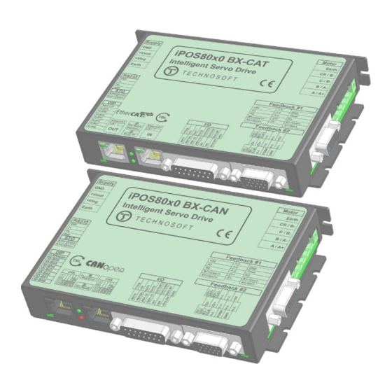
- Page 1 BX- CAN / CAT Intelligent Servo Drive Intelligent Servo Drives for Step, DC, Brushless DC and AC Motors Technical Reference Technosoft 2019 P091.029.iPOS80x0.BX.UM.0719...
-
Page 2: Table Of Contents
2.4.1 Single loop configurations ........................11 ..2.4.2 Dual loop configurations ........................12 Hardware Installation ..................... 12 iPOS80x0 BX-CAN/CAT Board Dimensions ............. 12 Mechanical Mounting ....................13 Connectors and Pinouts .................... 13 ..3.3.1 Pinouts for iPOS80x0 BX-CAN ......................13 .. - Page 3 RS-232 ..............................38 ..3.8.19 CAN-Bus (for CAN drives) ........................38 ..3.8.22 Safe Torque OFF (STO1+; STO1-; STO2+; STO2-) ................39 ..3.8.24 De-rating graphs for CAN drives ......................40 Memory Map ......................41 Technosoft 2019 iPOS80x0 BX-CAN/-CAT Technical Reference...
-
Page 4: Read This First
Whilst Technosoft believes that the information and guidance given in this manual is correct, all parties must rely upon their own skill and judgment when making use of it. Technosoft does not assume any liability to anyone for any loss or damage caused by any error or omission in the work, whether such error or omission is the result of negligence or any other cause. -
Page 5: Related Documentation
SI units and the drive internal units. Help of the EasySetUp software – describes how to use EasySetUp to quickly setup any Technosoft drive for your application using only 2 dialogues. The output of EasySetUp is a set of setup data that can be downloaded into the drive EEPROM or saved on a PC file. -
Page 6: If You Need Assistance
DISCONNECT WIRES FROM THE DRIVE WHILE THE POWER SUPPLIES ARE ON WARNING! THE DRIVE MAY HAVE HOT SURFACES DURING OPERATION. DURING DRIVE OPERATION, THE CONTROLLED MOTOR WILL MOVE. KEEP WARNING! AWAY FROM ALL MOVING PARTS TO AVOID INJURY Technosoft 2019 iPOS80x0 BX-CAN/-CAT Technical Reference... -
Page 7: Cautions
Evaluation, Authorization and Restriction of Chemicals), which came into force on 01.06.2007. RoHS Compliance - Technosoft SA here with declares that this product is manufactured in compliance with the RoHS directive 2002/95/EC on the restriction of the use of certain... -
Page 8: Product Overview
PLC functionality in a single compact unit and are capable to execute complex motions without requiring intervention of an external motion controller. Using the high-level Technosoft Motion Language (TML) the following operations can be executed directly at drive level: ... -
Page 9: Product Features
Hence neither the iPOS80x0 TML programming capability nor the drive camming mode are used. EasySetUp can be downloaded free of charge from Technosoft web page. EasyMotion Studio platform includes EasySetUp for the drive setup, and a Motion Wizard for the motion programming. - Page 10 • CANopen – conforming with CiA 301 v4.2, CiA WD 305 v2.2.13 and CiA DSP 402 v3.0 • TMLCAN – intelligent drive conforming with Technosoft protocol for exchanging TML commands via CAN-bus • EtherCAT® supported protocols for for CAT drives: •...
-
Page 11: Identification Labels
FDBK #2 (diff.) BiSS-C FDBK #2 (diff.) Analogue Sin/Cos encoder FDBK #1* (diff.) Tacho Analogue input: Feedback Open-loop (no sensor) Open-loop (with step loss detection FDBK #1* (diff.) using FDBK #2 (diff.) Incr. Encoder/SinCos/SSI/BiSS) Technosoft 2019 iPOS80x0 BX-CAN/-CAT Technical Reference... -
Page 12: Dual Loop Configurations
-DC brush motor with SSI encoder (from feedback #2) on motor and Sin/Cos encoder (from feedback #1) on load. Hardware Installation iPOS80x0 BX-CAN/CAT Board Dimensions Figure 3.1.1. iPOS80x0 BX-CAN/CAT drive dimensions Technosoft 2019 iPOS80x0 BX-CAN/-CAT Technical Reference... -
Page 13: Mechanical Mounting
The metallic support must act as a cooling heat sink. For thermal calculations, use the graphs below. Power Losses @10A applies to iPOS8010 and Power Losses @20A applies to iPOS8020. Connectors and Pinouts 3.3.1 Pinouts for iPOS80x0 BX-CAN Technosoft 2019 iPOS80x0 BX-CAN/-CAT Technical Reference... -
Page 14: Mating Connectors For Can And Cat
15-pin D-Sub I/O ; Analog male, DB15 MICROFIT RECEPTACLE MOLEX 43025-0400 HOUSING, 2x2 WAY CRIMP PIN, MICROFIT, 5A MOLEX 43030-0007 Standard 8P8C modular jack J6,J7 (RJ-45) male 3.3.3 Pinouts for iPOS80x0 BX-CAT Technosoft 2019 iPOS80x0 BX-CAN/-CAT Technical Reference... -
Page 15: Connection Diagrams
Connection diagrams 3.4.1 iPOS80x0 BX-CAN connection diagram Figure 3.2. iPOS80x0 BX-CAN Connection diagram * The digital inputs can be configured as PNP/NPN type in software setup * For other available feedback / motor options, check the detailed connection diagrams below ... -
Page 16: Ipos80X0 Bx-Cat Connection Diagram
* The digital inputs can be configured as PNP/NPN type in software setup * For other available feedback / motor options, check the detailed connection diagrams below * For a detailed EtherCAT bus connection diagram see Figure 3.26. EtherCAT wiring. Technosoft 2019 iPOS80x0 BX-CAN/-CAT Technical Reference... -
Page 17: Digital I/O Connection
The inputs are compatible with NPN type outputs (input must be pulled to GND to change its default state) The length of the cables must be up to 30m, reducing the exposure to voltage surges in industrial environment. Technosoft 2019 iPOS80x0 BX-CAN/-CAT Technical Reference... -
Page 18: Npn Outputs
Figure 3.6. 24V Digital NPN Outputs connection Remark: The outputs are compatible with NPN type inputs (load is tied to common +V , output pulls to GND when active and is floating when inactive) Technosoft 2019 iPOS80x0 BX-CAN/-CAT Technical Reference... -
Page 19: Analog Inputs Connection
For all of the above cases, connect the cable shield to the drive GND and leave the other shield end unconnected to the signal source. To further increase the noise protection, use a double shielded cable with inner shield connected to drive GND and outer shield connected to the motor chassis (earth). Technosoft 2019 iPOS80x0 BX-CAN/-CAT Technical Reference... -
Page 20: Motor Connections
Figure 3.10. 2-phase step motor connection, one coil per phase Remark: To hardware enable the motor outputs, connect STO1+ and STO2+ pins to +Vlog and STO1- and STO2- to GND. Figure 3.11. 2-phase step motor connection, two coils per phase Technosoft 2019 iPOS80x0 BX-CAN/-CAT Technical Reference... -
Page 21: 3-Phase Step Motor Connection
Each inductor shall be 15 µH minimum, rated for the motor peak current and preferably magnetically shielded (toroidal, for example). A good shielding can be obtained if the motor wires are running inside a metallic cable guide. Technosoft 2019 iPOS80x0 BX-CAN/-CAT Technical Reference... -
Page 22: Feedback Connections
The encoder #2 input has internal terminators, equivalent to 120Ω (0.25W) , present in the drive. The length of the cables must be up to 30m, reducing the exposure to voltage surges in industrial environment. Technosoft 2019 iPOS80x0 BX-CAN/-CAT Technical Reference... -
Page 23: Pulse And Direction Connection
Figure 3.16. J4 – Master – Slave connection using encoder#2 input 3.4.6.3 Pulse and direction connection Figure 3.17. Pulse and direction connection Remark: the same pulse and direction connection can be done on J3 Encoder#1 using the same pin numbers as for Encoder#2 Technosoft 2019 iPOS80x0 BX-CAN/-CAT Technical Reference... -
Page 24: Sine-Cosine Analog Encoder Connection
The digital halls are not used in this case as a feedback measurement device. The actual motor control is done with an incremental encoder. The length of the cables must be up to 30m, reducing the exposure to voltage surges in industrial environment. Technosoft 2019 iPOS80x0 BX-CAN/-CAT Technical Reference... -
Page 25: Ssi Encoder #2 Connection
The encoder #2 input has an internal terminator between pins 2 and 3, equivalent to 120Ω (0.25W) , present in the drive. The length of the cables must be up to 30m, reducing the exposure to voltage surges in industrial environment. Technosoft 2019 iPOS80x0 BX-CAN/-CAT Technical Reference... -
Page 26: Power Supply And Sto Connection
The capacitor must be rated to a voltage equal or bigger than the maximum expected over-voltage and can be sized with the formula: × ≥ − where: = 84V is the over-voltage protection limit is the nominal motor supply voltage Technosoft 2019 iPOS80x0 BX-CAN/-CAT Technical Reference... - Page 27 CHOP where C is the capacitance on the motor supply (external), i.e: < CHOP × to limit the average current below the drive nominal current I =20A (for 8010) and 20A (for 8020) Technosoft 2019 iPOS80x0 BX-CAN/-CAT Technical Reference...
-
Page 28: Serial Rs-232 Connection
232Tx signals. All metallic connector shells are connected internally to the Earth connector J1 pin 4. Always power-off all the iPOS80x0 BX-CAN supplies before inserting/removing the RS-232 serial connector Do not rely on an earthed PC to provide the iPOS80x0 GND connection! The drive must be earthed through a separate circuit. -
Page 29: Can-Bus Connection (For Can Drives Only)
105 ... 135 ohms (120 ohms typical) and a capacitance below 30pF/meter. The 120Ω termination resistors must be rated at 0.2W minimum. Do not use winded resistors, which are inductive. Figure 3.25. Multiple-Axis CAN network Technosoft 2019 iPOS80x0 BX-CAN/-CAT Technical Reference... -
Page 30: Recommendations For Ethercat Wiring (For Cat Drives)
NOT guarantee a stable and reliable connection! This can only be guaranteed by proper quality of cables used, according to TIA/EIA-568-B specifications. Figure 3.26. EtherCAT wiring Figure 3.27. EtherCAT network linear topology Figure 3.28. EtherCAT network ring topology Technosoft 2019 iPOS80x0 BX-CAN/-CAT Technical Reference... -
Page 31: Disabling Autorun (For Can Drives); Disabling The Setup Table At Startup (For Cat Drives)
Disabling Autorun (for CAN drives) When an iPOS80x0 BX-CAN is set in TMLCAN operation mode, by default after power-on it enters automatically in Autorun mode. In this mode, if the drive has in its local EEPROM a valid TML application (motion program), this is automatically executed as soon as the motor supply V is turned on. -
Page 32: Can Operation Mode And Axis Id Selection For Can Drives(Sw1 Settings)
0. In total, 127 axis ID HW values can result from the DIP switch combinations. When pins 2..8 remain OFF, the drive Axis ID will be 255 and configured station alias will be 0. All pins are sampled at power-up, and the drive is configured accordingly. Technosoft 2019 iPOS80x0 BX-CAN/-CAT Technical Reference... -
Page 33: Led Indicators
STATUS indicator combines the behavior of the RUN indicator specified in Table 3.3 and the behavior of the ERROR indicator specified in Table 3.4. Figure 3.34. STATUS indicator Example Technosoft 2019 iPOS80x0 BX-CAN/-CAT Technical Reference... -
Page 34: Electrical Specifications
In case of forced cooling (conduction or ventilation) the spacing requirements may drop down to mechanical tolerances as long as the ambient temperature is kept below the maximum operating limit Technosoft 2019 iPOS80x0 BX-CAN/-CAT Technical Reference... -
Page 35: Logic Supply Input
Input voltage Floating voltage (not connected) Absolute maximum, continuous Absolute maximum, surge (duration ≤ 1s) † Input current Logic “LOW”; Pulled to GND -1.6 The digital inputs are software selectable as PNP or NPN Technosoft 2019 iPOS80x0 BX-CAN/-CAT Technical Reference... -
Page 36: Digital Outputs (Out0, Out1, Out2/Error, Out3/ Ready)
A1+, A2+, B1+, B2+, Z1+, Z2+ kΩ A1-, A2-, B1-, B2-, Z1-, Z2- Input impedance, differential Differential mode Differential mode ESD protection Human body model ±1 All differential input pins have internal 120 Ω termination resistors connected across Technosoft 2019 iPOS80x0 BX-CAN/-CAT Technical Reference... -
Page 37: Encoder #2 Inputs (A2+, A2-, B2+, B2-, Z2+, Z2-)
For many applications, a termination resistor should be connected across SIN+ to SIN-, and across COS+ to COS-. This can be achieved by setting SW3 pins 3,4 and 5 to ON. Please consult the feedback device datasheet for confirmation. Technosoft 2019 iPOS80x0 BX-CAN/-CAT Technical Reference... -
Page 38: Biss Encoder Interface
Hardware: by H/W pins (CANopen); Node addressing 1-127 & 255 (TMLCAN) Software 1 ÷ 127 (CANopen); 1- 255 (TMLCAN) Voltage, CAN-Hi or CAN-Lo to GND ESD protection Human body model ±15 “FS” stands for “Full Scale” Technosoft 2019 iPOS80x0 BX-CAN/-CAT Technical Reference... -
Page 39: Safe Torque Off (Sto1+; Sto1-; Sto2+; Sto2-)
EC 428/2009 (non dual-use item, output frequency limited to 590Hz) † Stresses beyond values listed under “absolute maximum ratings” may cause permanent damage to the device. Exposure to absolute-maximum-rated conditions for extended periods may affect device reliability. Technosoft 2019 iPOS80x0 BX-CAN/-CAT Technical Reference... -
Page 40: Rating Graphs For Can Drives
Figure 3.36 iPOS8020 BX-CAN temperature temperature Figure 3.37 iPOS8010 BX-CAN Over-current diagram Figure 3.38 iPOS8020 BX-CAN Over-current diagram Figure 3.39. iPOS80x0 BX-CAN Output Voltage De-rating with Figure 3.40. iPOS80x0 BX-CAN De-rating with altitude PWM frequency CAUTION! FOR PWM FREQUENCIES LESS THAN 20... -
Page 41: Memory Map
4000h ROM memory for: TML programs Cam tables Setup information 7FFFh 8000h Reserved 8FFFh Data acquisitions C000h cam tables at runtime SRAM memory TML Programs FFFFh Figure 7.1. iPOS80x0 BX Memory Map Technosoft 2019 iPOS80x0 BX-CAN/-CAT Technical Reference...
Need help?
Do you have a question about the iPOS80x0 BX-CAN and is the answer not in the manual?
Questions and answers