
Related Manuals for Technosoft iPOS4808 BX-CAT-STO


Summary of Contents for Technosoft iPOS4808 BX-CAT-STO
- Page 1 BX-CAT-STO Intelligent Servo Drive for Step, DC, Brushless DC and AC Motors Intelligent Servo Drives Technical Reference Technosoft 2017 P091.027.iPOS4808.BX.CAT.STO.UM.0317...
-
Page 2: Table Of Contents
2.4.1 Single loop configurations ...................... 11 ..2.4.2 Dual loop configurations ......................11 Hardware Installation ..................... 12 iPOS4808 BX-CAT-STO Board Dimensions .............. 12 Mechanical Mounting ....................13 Connectors and Pinouts .................... 14 ..3.3.1 Pinouts for iPOS4808 BX-CAT-STO ..................14 .. - Page 3 BiSS Encoder Interface......................36 ..3.6.17 Analog 0…5V Inputs (REF, FDBK) ..................36 ..3.6.18 RS-232 ........................... 36 ..3.6.21 Safe Torque OFF (STO1+; STO1-; STO2+; STO2-) ............. 37 Memory Map ......................38 Technosoft 2017 iPOS4808 BX-CAT-STO Technical Reference...
-
Page 4: Read This First
Whilst Technosoft believes that the information and guidance given in this manual is correct, all parties must rely upon their own skill and judgment when making use of it. Technosoft does not assume any liability to anyone for any loss or damage caused by any error or omission in the work, whether such error or omission is the result of negligence or any other cause. -
Page 5: Related Documentation
SI units and the drive internal units. Help of the EasySetUp software – describes how to use EasySetUp to quickly setup any Technosoft drive for your application using only 2 dialogues. The output of EasySetUp is a set of setup data that can be downloaded into the drive EEPROM or saved on a PC file. -
Page 6: Safety Information
AWAY FROM ALL MOVING PARTS TO AVOID INJURY Cautions THE POWER SUPPLIES CONNECTED TO THE DRIVE MUST COMPLY WITH THE CAUTION! PARAMETERS SPECIFIED IN THIS DOCUMENT TROUBLESHOOTING SERVICING PERMITTED ONLY CAUTION! PERSONNEL AUTHORISED BY TECHNOSOFT Technosoft 2017 iPOS4808 BX-CAT-STO Technical Reference... -
Page 7: Quality System, Conformance And Certifications
Evaluation, Authorization and Restriction of Chemicals), which came into force on 01.06.2007. RoHS Compliance - Technosoft SA here with declares that this product is manufactured in compliance with the RoHS directive 2002/95/EC on the restriction of the use of certain... -
Page 8: Product Overview
PLC functionality in a single compact unit and are capable to execute complex motions without requiring intervention of an external motion controller. Using the high-level Technosoft Motion Language (TML) the following operations can be executed directly at drive level: ... -
Page 9: Product Features
Various modes of operation, including: cyclic synchronous torque, velocity or position control(CST, CSV or CSP); position or velocity profiles, external analogue reference or sent via a communication bus • Technosoft Motion Language (TML) instruction set for the definition and execution of motion sequences • Standalone operation with stored motion sequences •... -
Page 10: Identification Labels
The iPOS4808 BX-CAT can have the following part numbers and names on the identification label: p.n. P027.314.E221 name iPOS4808 BX-CAT-STO – standard EtherCAT® execution p.n. P027.324.E721 name iPOS4808 BX-CAT-STO – Linear Hall EtherCAT® execution 20A cont. with DC, step and BLDC motors (trapezoidal), 20A amplitude (14.2A ) for PMSM (sinusoidal) ... -
Page 11: Supported Motor-Sensor Configurations
-DC brush motor with SSI encoder (from feedback #2) on motor and Sin/Cos encoder (from feedback #1) on load. A differential encoder on Feedback #1 is available only with P027.314.E221 Linear hall sensors are compatible only with P027.314.E721 Technosoft 2017 iPOS4808 BX-CAT-STO Technical Reference... -
Page 12: Hardware Installation
Hardware Installation iPOS4808 BX-CAT-STO Board Dimensions Figure 3.1.1. iPOS4808 BX-CAT-STO drive dimensions All dimensions are in mm. The drawings are not to scale. Technosoft 2017 iPOS4808 BX-CAT-STO Technical Reference... -
Page 13: Mechanical Mounting
3.3.2 Mating Connectors. For thermal calculations, the iPOS4808 BX-CAT-STO drive can be assumed to generate 3.7 Watt (= 8 BTU/hour) at idle, and up to 7.2 Watt (= 25 BTU/hour) worst case while driving a motor. -
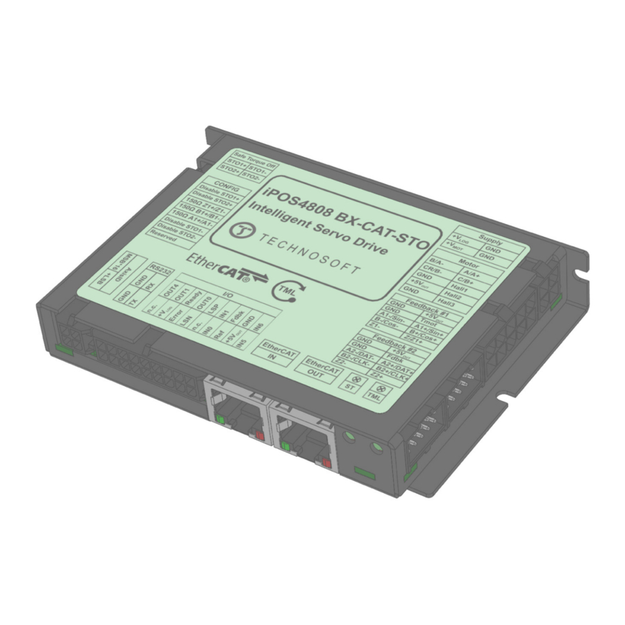
Page 14: Connectors And Pinouts
Connectors and Pinouts 3.3.1 Pinouts for iPOS4808 BX-CAT-STO Technosoft 2017 iPOS4808 BX-CAT-STO Technical Reference... -
Page 15: Mating Connectors
Standard 8P8C modular jack (RJ-45) male Connection diagrams 3.4.1 iPOS4808 BX-CAT-STO connection diagram Figure 3.2. iPOS4808 BX-CAT-STO Connection diagram * For other available feedback / motor options, check the detailed connection diagrams below Technosoft 2017 iPOS4808 BX-CAT-STO Technical Reference... -
Page 16: 24V Digital I/O Connection
The inputs are compatible with NPN type outputs (input must be pulled to GND to change its default state) The length of the cables must be up to 30m, reducing the exposure to voltage surges in industrial environment. Technosoft 2017 iPOS4808 BX-CAT-STO Technical Reference... -
Page 17: Npn Outputs
The length of the cables must be up to 30m, reducing the exposure to voltage surges in industrial environment. The output loads can be individually and independently connected to +5V or to GND. Technosoft 2017 iPOS4808 BX-CAT-STO Technical Reference... -
Page 18: Analog Inputs Connection
(GND); shield is connected only at the drive side, to the drive GND, and is left unconnected at the source side. The source minus (negative, out-of-phase) output remains unconnected. Technosoft 2017 iPOS4808 BX-CAT-STO Technical Reference... -
Page 19: Motor Connections
Brushless Motor connection Figure 3.9. Brushless motor connection 3.4.5.2 2-phase Step Motor connection Figure 3.10. 2-phase step motor connection, one coil per phase Figure 3.11. 2-phase step motor connection, two coils per phase Technosoft 2017 iPOS4808 BX-CAT-STO Technical Reference... -
Page 20: 3-Phase Step Motor Connection
The inductors must be magnetically shielded (toroidal, for example), and must be rated for the motor surge current. Typically the necessary values are around 100 μH. A good shielding can be obtained if the motor wires are running inside a metallic cable guide. Technosoft 2017 iPOS4808 BX-CAT-STO Technical Reference... -
Page 21: Feedback Connections
3.4.6.2 Differential Incremental Encoder #1 Connection Figure 3.15. Differential incremental encoder #1 connection Remarks: The length of the cables must be up to 30m, reducing the exposure to voltage surges in industrial environment. Technosoft 2017 iPOS4808 BX-CAT-STO Technical Reference... -
Page 22: Single-Ended Incremental Encoder #1 Connection
The encoder #2 input has internal terminators, equivalent to 120Ω (0.25W) , present in the drive. The length of the cables must be up to 30m, reducing the exposure to voltage surges in industrial environment. Technosoft 2017 iPOS4808 BX-CAT-STO Technical Reference... -
Page 23: Ssi Encoder #2 Connection
The encoder #2 input has internal terminators, equivalent to 120Ω (0.25W) , present in the drive. The length of the cables must be up to 30m, reducing the exposure to voltage surges in industrial environment. Technosoft 2017 iPOS4808 BX-CAT-STO Technical Reference... -
Page 24: Digital Hall Connection For Motor + Hall + Incremental Encoder
This connection is required when using only Digital hall signals as the main feedback device for motor control. In this case, no incremental encoder is needed. The length of the cables must be up to 30m, reducing the exposure to voltage surges in industrial environment. Technosoft 2017 iPOS4808 BX-CAT-STO Technical Reference... -
Page 25: Sine-Cosine Analog Encoder Connection
5 meters, add a decoupling capacitor near the supplied device, between the +5V and GND lines. The capacitor value can be 1...10 μF, rated at 6.3V. A linear hall connection is possible only with the drive Product ID: P027.314.E721 Technosoft 2017 iPOS4808 BX-CAT-STO Technical Reference... -
Page 26: Power Supply And Sto Connection
Option 1. Add a capacitor on the motor supply big enough to absorb the overall energy flowing back to the supply. The capacitor must be rated to a voltage equal or bigger than the maximum expected over-voltage and can be sized with the formula: × ≥ − Technosoft 2017 iPOS4808 BX-CAT-STO Technical Reference... - Page 27 I = 0.9A PEAK > PEAK to sustain the required braking power: − − CHOP where C is the capacitance on the motor supply (external), i.e: Technosoft 2017 iPOS4808 BX-CAT-STO Technical Reference...
-
Page 28: Serial Rs-232 Connection
Do not rely on an earthed PC to provide the iPOS4808 GND connection! The drive must be earthed through a separate circuit. Most communication problems are caused by the lack of such connection Technosoft 2017 iPOS4808 BX-CAT-STO Technical Reference... -
Page 29: Recommendations For Ethercat Wiring
NOT guarantee a stable and reliable connection! This can only be guaranteed by proper quality of cables used, according to TIA/EIA-568-B specifications. Figure 3.26. EtherCAT wiring Figure 3.27. EtherCAT network linear topology Figure 3.28. EtherCAT network ring topology Technosoft 2017 iPOS4808 BX-CAT-STO Technical Reference... -
Page 30: 3.4.10 Disabling The Setup Table At Startup
Remark: in an EtherCAT network, some masters accept multiple drives with the same configured station alias only if its value is 0. In a normal operation each drive should have its own unique AxisID on a network. Technosoft 2017 iPOS4808 BX-CAT-STO Technical Reference... -
Page 31: Led Indicators
1 in AL Status register No error The EtherCAT communication of the device is in working condition For a more detailed description of EtherCAT® LED functionalities please read ETG.1300 S (R) V1.0.1 available at www.EtherCAT.org Technosoft 2017 iPOS4808 BX-CAT-STO Technical Reference... -
Page 32: Electrical Specifications
In case of forced cooling (conduction or ventilation) the spacing requirements may drop down to mechanical tolerances as long as the ambient temperature is kept below the maximum operating limit Technosoft 2017 iPOS4808 BX-CAT-STO Technical Reference... -
Page 33: Motor Outputs (A/A+, B/A-, C/B+, Cr/B-)
Logic “LOW”; Pulled to GND -1.6 Input current Logic “HIGH”; Pulled to +24V Input frequency Minimum pulse width µs ESD protection Human body model ±2 The digital inputs are software selectable as PNP or NPN Technosoft 2017 iPOS4808 BX-CAT-STO Technical Reference... -
Page 34: Digital Outputs (Out0, Out1, Out2/Error, Out3/ Ready, Out4)
Encoder #1 differential input pins needs termination resistors connected across; set SW3 pins 3,4 and 5 to ON For full RS-422 compliance, 120Ω termination resistors must be connected across the differential pairs, set SW3 pins 3,4 and 5 to connection ON. See Figure 3.16. Differential incremental encoder #1 Technosoft 2017 iPOS4808 BX-CAT-STO Technical Reference... -
Page 35: Encoder #2 Inputs (A2+, A2-, B2+, B2-, Z2+, Z2-)
For many applications, a termination resistor should be connected across SIN+ to SIN-, and across COS+ to COS-. This can be achieved by setting SW3 pins 3,4 and 5 to ON. Please consult the feedback device datasheet for confirmation. Technosoft 2017 iPOS4808 BX-CAT-STO Technical Reference... -
Page 36: 3.6.16 Biss Encoder Interface
TIA/EIA-568-A or TIA/EIA-568-B Software protocols compatibility CoE, CiA402, IEC61800-7-301 By software, via EasySetup 1 ÷ 255 Node addressing By hardware via hex sw1 and sw2 1 ÷ 127 “FS” stands for “Full Scale” Technosoft 2017 iPOS4808 BX-CAT-STO Technical Reference... -
Page 37: Safe Torque Off (Sto1+; Sto1-; Sto2+; Sto2-)
ESD protection Human body model ±2 † Stresses beyond values listed under “absolute maximum ratings” may cause permanent damage to the device. Exposure to absolute-maximum-rated conditions for extended periods may affect device reliability. Technosoft 2017 iPOS4808 BX-CAT-STO Technical Reference... -
Page 38: Memory Map
4000h ROM memory for: TML programs Cam tables Setup information 7FFFh 8000h Reserved 8FFFh Data acquisitions C000h cam tables at runtime SRAM memory TML Programs FFFFh Figure 7.1. iPOS4808 BX-CAT Memory Map Technosoft 2017 iPOS4808 BX-CAT-STO Technical Reference...
Need help?
Do you have a question about the iPOS4808 BX-CAT-STO and is the answer not in the manual?
Questions and answers