Table of Contents
Advertisement
Quick Links
Advertisement
Table of Contents

Related Manuals for THORLABS OTKB


Summary of Contents for THORLABS OTKB
- Page 1 Optical Trap Kit Manual...
-
Page 2: Table Of Contents
Setup Description and Segments ....................4 Optical Trap Kit Components ......................8 Force Measurement Module OTKBFM..................11 Setup and Alignment in Detail ....................12 Software Package ........................24 Sample preparation and measurement ..................24 Accessories ..........................25 Summary of Key Features and Specifications ................26 19590-D04-V15; Apr 12, 2012 Page 2 www.thorlabs.com... -
Page 3: Safety
Latex gloves should be worn to prevent oil from fingers from reaching all optical surfaces. Make sure you use appropriate laser safety glasses during operation. WARNING Avoid Exposure – ASE and laser radiation emitted from apertures. Never look directly in to beam. 19590-D04-V15; Apr 12, 2012 Page 3 www.thorlabs.com... -
Page 4: Introduction
Moreover, since Thorlabs‟ components are designed to be compatible with each other, the OTKB optical trapping kit is easily modified to provide additional functionalities as your research needs evolve. For example, adding the ability to steer / scan the optical trap position. - Page 5 Section 6.2, steps 14) to 16). Align the dichroic as described in same section, steps 21) to 22). The Vertical Segment Port Imaging Lens Screw to table The Collimator The Camera Segment Port Segment Port Figure 5.2: The Beam Expander Segment 19590-D04-V15; Apr 12, 2012 Page 5 www.thorlabs.com...
- Page 6 Next, mount the top part that was initially removed and to align this correctly, follow the instructions in Section 6.5, steps 16) to 21) Top Part. Remove initially for alignment C1500 that attaches lower Part to DP14 Connects to C6W here Figure 5.3: The Beam Expander Segment 19590-D04-V15; Apr 12, 2012 Page 6 www.thorlabs.com...
- Page 7 C6W, such that it doesn‟t interfere with the B4C. Then lock this segment to the C6W using the four set screws on the sides of the C6W. Camera Connects to C6W here Cage plate gasket, CPG3 Figure 5.4: The Beam Expander Segment 19590-D04-V15; Apr 12, 2012 Page 7 www.thorlabs.com...
-
Page 8: Optical Trap Kit Components
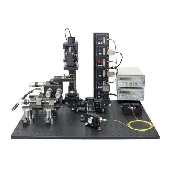
1.5″ post (Item # DP14). All of the parts discussed in this LDC210C section are included in the OTKB kit unless otherwise noted. Some of the parts mentioned below are not universal so the metric version of the part TED200C is used in the OTKB/M kit. - Page 9 Optical Trap Kit Figure 3.2: Model of Thorlabs Optical Trapping system 19590-D04-V15; Apr 12, 2012 Page 9 www.thorlabs.com...
- Page 10 9) A single emitter white light LED (Item # LEDWE-15,7.5 half angle forward radiating) is built into the component OTKB-LS-SP. The light from the LED illuminates the sample. 10) The OTKBFM force measurement module contains the hardware needed to calibrate the trap.
-
Page 11: Force Measurement Module Otkbfm
Figure 4.1: Force Measurement Module OTKBFM consisting of two TGS001, TQD001, PDQ80A and the cage assembly for connecting the detector and optics to the base kit. The shaded controllers and the USB hub TCH002 are included with the base kit OTKB 19590-D04-V15; Apr 12, 2012 Page 11 www.thorlabs.com... -
Page 12: Setup And Alignment In Detail
Though the system ships as five segments, the following steps provide a detailed, step by step set of instructions on how to assemble the optical trapping kit OTKB from individual parts. So, only parts of these detailed descriptions will have to be followed as indicated in Section 3. However, this gives you some detail of the assembly so that you can modify according to your application needs. - Page 13 CP08FP adapter and the other end of the KCB1 right angle mirror mount. The ensuing model is shown in Figure 6.1.2. 9) Temporarily attach two ER6 cage rods to the top two tapped holes on the output face of the KCB1. 19590-D04-V15; Apr 12, 2012 Page 13 www.thorlabs.com...
- Page 14 SM1V10 also. The SM1L10 should touch the other face of the CP02 as shown in Figure 5.2.1. 6. Clamp the CPB1 attached to the CP02 to table using the miniature rail clamp CL6. 7. Attach another SM1L10 to a new CP02. 19590-D04-V15; Apr 12, 2012 Page 14 www.thorlabs.com...
- Page 15 If the beam is off, you may need to correct this by small adjustments on the KCB1 mirror. 16. Remove the temporary ER6 cage rods and close the port on that face of the C6W cube using an SM1CP2. 19590-D04-V15; Apr 12, 2012 Page 15 www.thorlabs.com...
- Page 16 25. Mount the imaging lens, AC254-200-A into an SM1L05 and connect to the side port of the C6W as shown in Figure 6.2.2. The lens should be mounted such that the concave side is directed to camera. 19590-D04-V15; Apr 12, 2012 Page 16 www.thorlabs.com...
- Page 17 **Centering of the beam along this path is very critical. A Thorlabs power meter (not included) with an SM1 threaded measurement head (e.g., PM100D with S121C) will allow you to verify the alignment by maximizing the transmitted power when both apertures are nearly closed.
- Page 18 8. Insert the ensuing assembly from step 2 above on one side of the C6W and coarsely align it so that the beam is reflected 90˚ to the left (if you look at Figure 6.4.1, reflection will be out of 19590-D04-V15; Apr 12, 2012 Page 18 www.thorlabs.com...
- Page 19 12 and 13 to the C6W assembly as shown in Figure 5.4.2. Use the holes on the side with the C1500. The other holes will be used for alignment with the lower vertical segment. 19590-D04-V15; Apr 12, 2012 Page 19 www.thorlabs.com...
- Page 20 Figure 6.5.1 (Left) Aligning the upper vertical segment to the lower vertical segment using ER12 rods. (Right) Completing the upper vertical segment using two ER6 rods. 20. Remove one half of the SM1Q quick release adapter from the OTKB-LS-SP light source and attach it to the upper LCP02 cage plate.
- Page 21 Your trapping system is now complete and you can proceed to build the sample stage. If you use the force measurement module, see the integration instructions which were provided with the OTKBFM. 6.7 Sample Stage and Holder 1. Mount the TBB0606 translating breadboard onto the post assemblies P1.5 and base PB2. 19590-D04-V15; Apr 12, 2012 Page 21 www.thorlabs.com...
- Page 22 Figure 6.7.1: The sample stage and holder 6.8 The Light Source 1. Remove one half of the SM1Q quick release adapter from the OTKB-LS-SP light source and attach it to the upper LCP02 cage plate. Then connect the other half of the light source and lock in place by rotation.
- Page 23 6.9 Thorlabs Optical Trapping Test Accessories Thorlabs provides a set of accessories that allow the user to get started using the system and verify proper operation. This can be ordered as the item OTKBTK. This set includes the following items: 1.
-
Page 24: Software Package
QPD and Strain Gauge Controller software on top (included with OTKBFM) and the piezo controller software and CCD camera software at the bottom (included with OTKB (OTKB/M) Figure 5.1 (Left) Application Screen (Right) CCD camera application, 1 m Silica beads. -
Page 25: Accessories
To build this on a breadboard, you would need the MB1824 – (Aluminum Breadboard, 450 mm x x 1/2", 1/4"-20 Threaded) for imperial or the MB4560/M 600 mm x 12.7 mm, M6 Threaded) for metric. 19590-D04-V15; Apr 12, 2012 Page 25 www.thorlabs.com... -
Page 26: Summary Of Key Features And Specifications
Working Distance: 0.23mm Transmission: 380-1100nm Recommended Cover Glass thickness: 0.17mm Beam Diameter at Back Aperture of Nikon Objective: Ø4.74 mm Nikon 10X Air Condenser 0.25 NA Working Distance: 7mm Transmission: 380-1100nm 19590-D04-V15; Apr 12, 2012 Page 26 www.thorlabs.com... - Page 27 Optical Trap Kit Part 11. Thorlabs Worldwide Contacts USA, Canada, and South America Thorlabs, Inc. 435 Route 206 Newton, NJ 07860 Tel: 973-579-7227 Fax: 973-300-3600 www.thorlabs.com email: feedback@thorlabs.com Europe UK and Ireland Thorlabs GmbH Thorlabs LTD. Hans-Böckler-Str. 6 1 Saint Thomas Place, Ely...
- Page 28 Thorlabs, Inc. 435 Route 206N Newton, NJ 07860 USA Phone: (973) 579-7227 ♦ Fax: (973) 300-3600 www.thorlabs.com...
Need help?
Do you have a question about the OTKB and is the answer not in the manual?
Questions and answers