Table of Contents
Advertisement
Quick Links
Advertisement
Table of Contents

Related Manuals for THORLABS FSAC


Summary of Contents for THORLABS FSAC
- Page 1 FSAC Interferometric Autocorrelator User Guide...
-
Page 2: Table Of Contents
Chapter 8 Specifications ........................20 8.1. General Specifications ....................20 8.2. Electrical Requirements ....................20 8.3. Environmental Requirements ..................20 8.4. Mechanical Drawings ....................21 Chapter 9 Declaration of Conformity ....................22 Chapter 10 Regulatory ...........................23 Chapter 11 Thorlabs Worldwide Contacts ..................24... -
Page 3: Chapter 1 Warning Symbol Definitions
Interferometric Autocorrelator Chapter 1: Warning Symbol Definitions Chapter 1 Warning Symbol Definitions Below is a list of warning symbols you may encounter in this manual or on your device. Symbol Description Direct Current Alternating Current Both Direct and Alternating Current Earth Ground Terminal Protective Conductor Terminal Frame or Chassis Terminal... -
Page 4: Chapter 2 Safety
Interferometric Autocorrelator Chapter 2: Safety Chapter 2 Safety All statements regarding operational safety and technical data in this manual will only apply when the unit is operated correctly. WARNING Always wear appropriate laser safety eyewear during laser setup and operation. WARNING Use Appropriate Laser Safety Eyewear when Working with Lasers WARNING... -
Page 5: Chapter 3 Description
3.1. Introduction Thorlabs’ FSAC is an interferometric autocorrelator capable of quantitative and qualitative monitoring of ultrafast pulses from tens of femtoseconds to 1 picosecond. A modified Michelson interferometer splits an input pulse into two copies, modulates the delay between them, and recombines the pulses at a photodiode. Because the photodiode is not responsive over the fundamental wavelength band of typical Ti:sapphire lasers, two-photon absorption is required to generate photocurrent. -
Page 6: Chapter 4 Setup And Operation
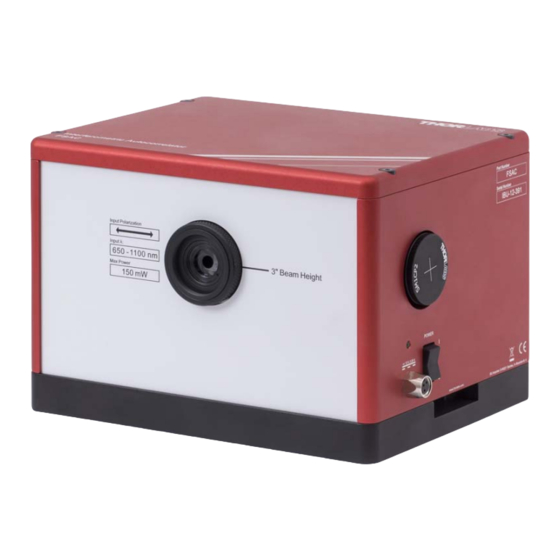
Always wear appropriate laser safety eyewear during laser setup and operation. The FSAC is roughly 7" x 6" (18 cm x 14 cm) in size and requires about 10" x 6" (25 cm x 14 cm) of optical table space when two CL5 mounting clamps are used to secure the FSAC to the table (see Figure 1). In this configuration, the autocorrelator beam height is 3"... - Page 7 90 degrees. Attach the VRC2SM1 fluorescent alignment target to the alignment aperture of the FSAC (Figure 3). The input aperture iris and the fluorescent alignment target provide two points which define the optical axis of the autocorrelator.
- Page 8 (level) to the table. M1 is adjusted to set the height of the beam, and M2 is used to level the beam, usually in alternating fashion. The FSAC may be moved towards M2 to check the height, and away from M2 to check the level.
-
Page 9: Operation And Fine Optical Alignment
4.3.2. Auto Shut Off When not in use, the FSAC should be turned off by the user. In order to preserve the lifetime of the device, the FSAC is equipped with an auto-shut-off feature. Once the device is turned on, it will automatically turn off after approximately 12 hours. -
Page 10: Fine Optical Alignment
The photodiode focus knob physically moves the position of the photodiode along the optical axis so it can be moved precisely to the focal point of the FSAC. A final knob switches the photodiode transimpedance amplifier gain from 0 to 70 dB in 10 dB steps. -
Page 11: Optimizing The Autocorrelation Trace
Interferometric Autocorrelator Chapter 4: Setup and Operation The autocorrelation trace should now be visible. Decrease the delay amplitude to better resolve the autocorrelation. You may now make small adjustments to M2 and the photodiode focus to optimize the signal. When the signal is optimized, it may no longer be perfectly centered on the alignment target. -
Page 12: Photodiode And Amplifier Bandwidth
Interferometric Autocorrelator Chapter 4: Setup and Operation Here, 5 Hz is the mirror scanning frequency, is the the peak-to-peak time delay of the delay mirror (typically greater than 5 times the expected pulse duration in order to operate within the linear range of the delay stage), 300 nm/fs is the speed of light, and is the central wavelength of the input laser. -
Page 13: Saturation
This is independent of the voltage output of the photodiode, so it may be observed even for low output signal levels. If this is found to be the case, then the average laser power of the beam entering the FSAC must be attenuated (by using a neutral density filter or a Fresnel reflection from an uncoated window, for example). -
Page 14: Peak To Background Ratio Too High/Low
FSAC detector and the oscilloscope or DAQ card. This level can be measured by blocking the input to the FSAC, and then the level may be subtracted from the entire interferometric autocorrelation trace. -
Page 15: Measuring Short (<40 Fs) Pulses
Measuring Short (<40 fs) Pulses It is important to understand that the measured pulse width using the FSAC is the width of the pulse just before the photodetector. Dispersion in media causes broadening in unchirped and positively chirped pulses. For a Gaussian... -
Page 16: Chapter 5 Theory And Interpretation
Working Principle Figure 11 shows the optical layout of the FSAC. The input beam pulse is split and copies are reflected from a delay mirror and a reference mirror and then recombined at the beamsplitter. The recombined beam is focused onto the detector. -
Page 17: Interferometric Autocorrelation Trace
Interferometric Autocorrelator Chapter 5: Theory and Interpretation ∗ d ∗ I t I t τ d , where ∗ denotes the complex conjugate. The first term is a constant background. The second term is a modified interferogram of which is responsible for fringes at the central frequency of its spectrum. The third term is the interferogram of the second harmonic of , and the fourth term is the intensity autocorrelation. -
Page 18: Excessive Chirp
Chapter 5: Theory and Interpretation is proportional to the input pulse FWHM by the factors in Table 2. Search for “FSAC” at Thorlabs’ website to find a sample MATLAB or Python script for converting interferometric autocorrelation data to an intensity autocorrelation trace. - Page 19 Interferometric Autocorrelator Chapter 5: Theory and Interpretation Figure 13 An interferometric autocorrelation of a chirped pulse transitions to an intensity autocorrelation in the wings. Pulse width estimation, in this case, is not straightforward. Page 17 Rev B, May 1, 2017...
-
Page 20: Chapter 6 Maintenance
Interferometric Autocorrelator Chapter 6: Maintenance Chapter 6 Maintenance The FSAC does not require regular maintenance. To maximize lifetime of the device, be sure it is powered off when not in use. Page 18 TT121442-D02... -
Page 21: Chapter 7 Warranty
Warranty Thorlabs warrants to the buyer of the system described in this manual that it conforms to the published specifications and is free from defects in materials and workmanship for a period of 12 months. The warranty period begins at installation or thirty days from shipment, whichever occurs first. -
Page 22: Chapter 8 Specifications
±12 VDC Power Consumption 6 W (Max) Connector Lumberg RSV3-657/2M Female Connector FSAC is designed to use the included Thorlabs LDS1212 power supply, which meets these requirements. 8.3. Environmental Requirements Environmental Requirements 17 °C to 25 °C Room Temperature Range Pulses as low as 15 fs may be measured with use of dispersion compensation. -
Page 23: Mechanical Drawings
Interferometric Autocorrelator Chapter 8: Specifications 8.4. Mechanical Drawings 6.90" (175.3 mm) 5.53" (140.4 mm) Permanently Attached Adjustable Iris (SM1D12D) Removable End Cap (SM1CP2) with Internal SM1 (1.035"-40) Port Used for Alignment Threads, 0.14" Deep 4.82" (122.4 mm) 3.00" (76.2 mm) M6 x 1.0 Tapped Hole, 1/4"-20 Tapped Hole, 0.25"... -
Page 24: Chapter 9 Declaration Of Conformity
Interferometric Autocorrelator Chapter 9: Declaration of Conformity Chapter 9 Declaration of Conformity Page 22 TT121442-D02... -
Page 25: Chapter 10 Regulatory
Waste Treatment is Your Own Responsibility If you do not return an “end of life” unit to Thorlabs, you must hand it to a company specialized in waste recovery. Do not dispose of the unit in a litter bin or at a public waste disposal site. -
Page 26: Chapter 11 Thorlabs Worldwide Contacts
Chapter 11 Thorlabs Worldwide Contacts For technical support or sales inquiries, please visit us at www.thorlabs.com/contact for our most up-to- date contact information. USA, Canada, and South America UK and Ireland Thorlabs, Inc. Thorlabs Ltd. sales@thorlabs.com sales.uk@thorlabs.com techsupport@thorlabs.com techsupport.uk@thorlabs.com Europe... - Page 27 www.thorlabs.com...
Need help?
Do you have a question about the FSAC and is the answer not in the manual?
Questions and answers