Advertisement
Quick Links
Advertisement

Related Manuals for THORLABS OTM200


Summary of Contents for THORLABS OTM200
- Page 1 OTM200 Optical Tweezer Add-On User Guide...
- Page 2 7.1. Laser Specifications ..................... 15 7.2. Power Requirements ..................... 15 7.3. Dimensions and Weights ....................15 Chapter 8 Regulatory ...........................16 8.1. Waste Treatment is Your Own Responsibility ............16 8.2. Ecological Background ....................16 Thorlabs Worldwide Contacts ..................17 Chapter 9 ...
- Page 3 OTM200 Chapter 1: Warning Symbol Definitions Chapter 1 Warning Symbol Definitions Below is a list of warning symbols you may encounter in this manual or on your device. Symbol Description Direct Current Alternating Current Both Direct and Alternating Current Earth Ground Terminal...
- Page 4 Ensure that the line voltage switch is set correctly for your local supply and that the appropriate fuses are installed. Fuses should only be changed by qualified service personnel. The OTM200 contains no user-serviceable parts. Do not operate without cover installed. Refer all maintenance to suitably qualified personnel.
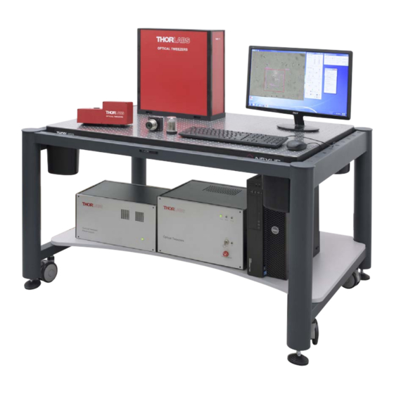
- Page 5 3.1. Introduction This document describes the optical tweezer add-on module OTM200 which is based on the microscope tweezer system, OTM211. The OTM200 system is intended for customers who are interested in adding trapping capabilities to a microscope. Therefore the product does not include a microscope and is configured for a specific microscope platform based on the user’s needs.
- Page 6 OTM200 Chapter 3: Description 3.3. Key System Features Multiple traps with computer control Adds trapping capabilities to existing inverted microscopes Software user interface with enhanced mouse control of multiple time shared traps Multiple trap pattern creation with arbitrary spacing – circles, lines, rectangles ...
- Page 7 OTM200 Chapter 3: Description 3.4. System Components The OTM200 includes the following modules: Optics Module 1.3NA trapping objective 1600 x 1200 CCD camera Electronics Control Module Power Supply Module Beam Dump and Interlock system ...
- Page 8 OTM200 Chapter 3: Description 3.5. Optics Module The optics module includes all the optical and opto-electronic components for creating and controlling multiple optical traps. The conditioned output beam is coupled into the microscope. A schematic for this module is shown below.
- Page 9 OTM200 Chapter 3: Description 3.6. Power Supply and Electronic Module These two modules provide power and contain the control circuitry for the components in the optics module. The rear panel of the power supply module has connection to the mains power supply and to the electronics module.
- Page 10 4.2. Graphical User Interface The OTM200 system comes with a pre-installed software which contains everything needed for system control and data acquisition. In addition an SDK is provided to allow users to easily create applications optimized for their particular requirements.
- Page 11 The speed and step size for the trap movement are adjustable and can be optimized, e.g. when switching between different objectives. The analysis tools button is disabled in the OTM200 configuration. It can be enabled by purchasing an upgrade adding for measurement capabilities to the OTM200 system.
- Page 12 Chapter 5: Operating Conditions and Environmental Requirements Chapter 5 Operating Conditions and Environmental Requirements The system will be installed by a member of the Thorlabs team. In preparation for install, the following considerations should be taken into account. 5.1. Selecting a Suitable Operation Environment In order to deliver optimal performance we recommend installing the Optical Tweezers System on an actively vibration-damped surface.
- Page 13 OTM200 Chapter 6: System Connections and Care Chapter 6 System Connections and Care 6.1. Module Connections The figure below shows the schematic for the rear panel connections for the optics, electronics, and power supply modules. DC Power Out Max. 300W +/-15VDC Max.
- Page 14 OTM200 Chapter 6: System Connections and Care 6.2. Service Only trained Thorlabs personnel are allowed to open any of the modules to service the system. Please contact Thorlabs Technical Support for more information. 6.3. Accessories and Customization The Thorlabs Microscope Tweezers Add-on System can be offered in several configurations, e.g. different microscope platforms, different camera models, different wavelength, optical power levels, integrated with additional imaging modalities.
- Page 15 OTM200 Chapter 7: Specifications Chapter 7 Specifications 7.1. Laser Specifications Laser Specifications 1064 nm Center Wavelength <0.25 nm Emission Bandwidth (FWHM) Output Power (before split) Panda 980 Fiber Linear Polarization State <0.2% Output Power instabilities (rms) Gaussian, with M <1.1 Output Beam Shape 7.2.
- Page 16 Waste Treatment is Your Own Responsibility If you do not return an “end of life” unit to Thorlabs, you must hand it to a company specialized in waste recovery. Do not dispose of the unit in a litter bin or at a public waste disposal site.
- Page 17 OTM200 Chapter 9: Thorlabs Worldwide Contacts Chapter 9 Thorlabs Worldwide Contacts For technical support or sales inquiries, please visit us at www.thorlabs.com/contact for our most up-to- date contact information. USA, Canada, and South America UK and Ireland Thorlabs, Inc. Thorlabs Ltd.
- Page 18 www.thorlabs.com...
Need help?
Do you have a question about the OTM200 and is the answer not in the manual?
Questions and answers